Figures & data
Table 1. Quantum version of machine learning.
Table 2. Comparison of Quantum Algorithms.
Figure 1. The overall idea of this paper.
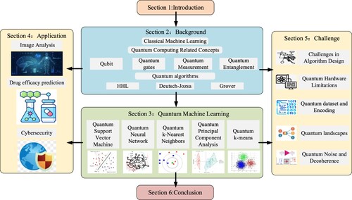
Table 3. Basic quantum gates.
Figure 2. HHL Algorithm Circuit Diagram.
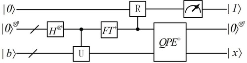
Figure 3. Schematic diagram of Deutsch-Jozsa circuit.
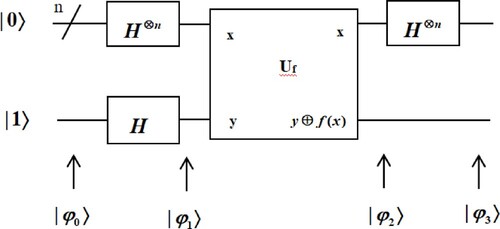
Figure 4. Four distinct approaches to combining quantum computing and machine learning.
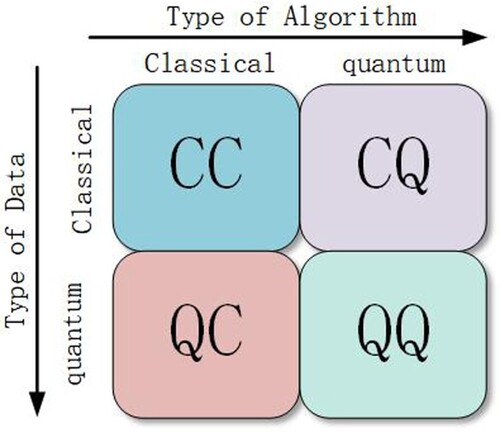
Figure 5. Visualisation of the classification boundary resulting by the classical SVM (a), and the quantum SVM (b-d) (Willsch et al., Citation2020).
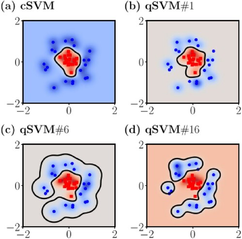
Figure 6. The quantum Hopfield neural network serves as a content-addressable memory system applied in RNA recognition.
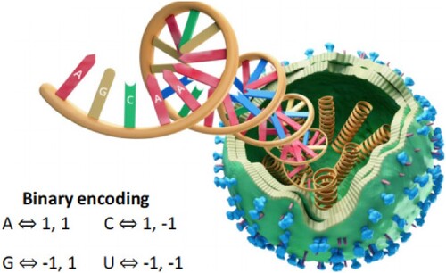
Figure 7. Controlled swap unitary gate.
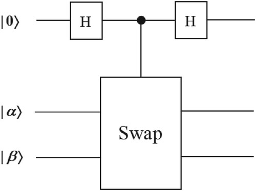
Figure 8. An example of 25 handwritten digits. Each digit is stored as a 256-pixel greyscale image and represented as a unit vector with N = 256 features.
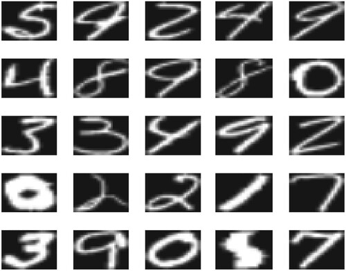
Figure 9. Schematic process for processing raw data into feature vectors into distances for handwriting recognition.
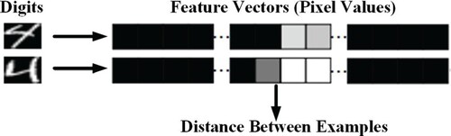
Figure 10. The schematic diagram of Principal Component Analysis (PCA). Note that the image was originally presented in (Fakultat, Citation2006).
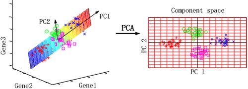
Figure 11. Simulation circuit of proposed qPCA for the 2 × 2 matrix A0 on IBM QX.
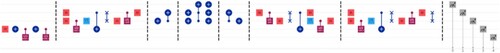
Figure 12. Quantum-swap-test-circuit Where represents the centroid cluster, and
represents the new data point for which its corresponding cluster is to be identified.
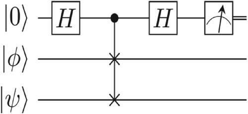
Figure 13. Data mapping diagram.
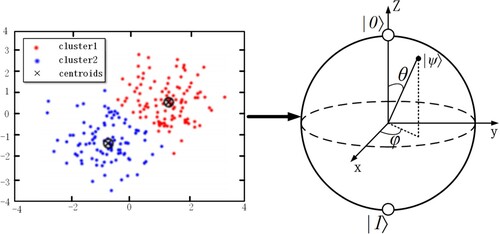
Table 4. Comparison of advantages and disadvantages of existing quantum machine learning algorithms.
Figure 14. Brain tumour image analysis.
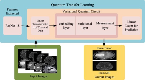
Figure 15. The overall framework diagram of the hybrid quantum neural network for drug efficacy prediction.
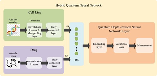
Table 5. The challenges of different quantum machine learning algorithms.
Figure 16. Progress of Quantum Computers and the Quantity of Quantum Bits.
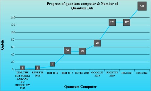
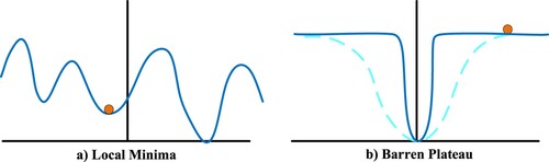
Figure 17. Quantum landscapes.