
Figures & data
Figure 1. Two acceptable layouts where the bathroom object is shielded from the vision limit line, adapted from (Department of Building and Housing, Citation2011).

Figure 2. Class diagram of spatial theory solving via Clingo’s python API.
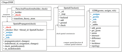
Figure 3. An alternative interpretation of the privacy code based on visibility space, regions from which an object is visible (Bhatt et al., Citation2012).
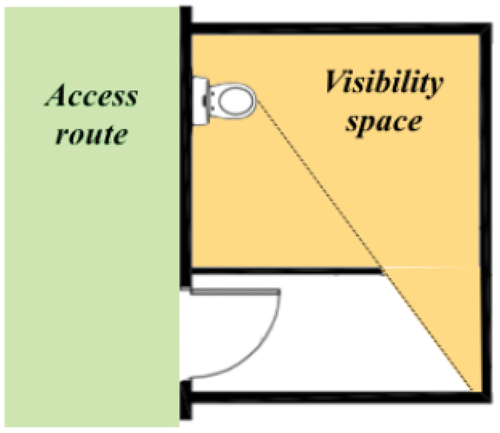
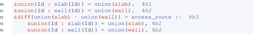
Figure 4. Cascading spatial evaluations.

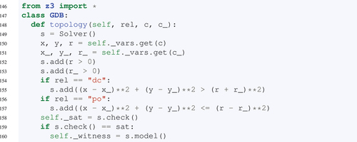
Figure 5. Class attributes and methods for the geometry database.
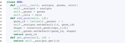
Figure 6. Topological relation partial overlap between two regions as defined in −5, and incidence relation inside between points and regions.

Table 1. Spatial functions in Clingo2DSR
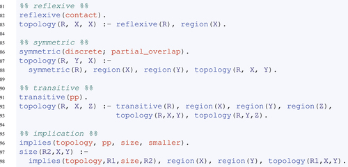
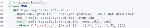
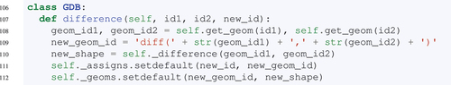
Figure 7. 2D footprints of functional spaces of common bathroom objects. Taken from (Neufert et al., Citation2000).

Table
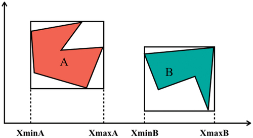
Figure 8. Deducing topological relations disconnected between two regions a and B by comparing their bounding box coordinates.

Table

Table
Table
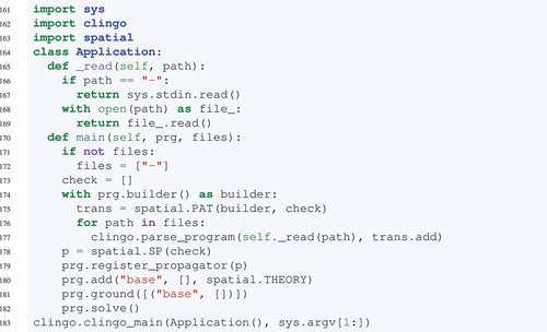
Figure 9. Shape of the th input polygon in the empirical experiments, for
.
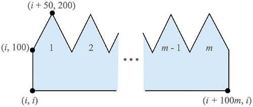
Table 2. Runtime (seconds) of four stages for and
in experiment 1.
Figure 10. Plot of experiment 1 comparing input size (teeth per polygon) with computational runtime of spatial computation, for fixed number of polygons,
.
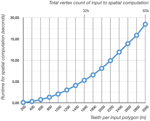
Table 3. Results of experiment 2 comparing number of polygons () given as input to the experiment 2 ASP program with the solving and spatial runtimes, and the number of spatial function applications, with and without the GDB feature of storing and retrieving spatial computation results.
Figure 11. Minimum clearance requirements between successive doors on access routes. Taken directly from (Department of Building and Housing, Citation2011).
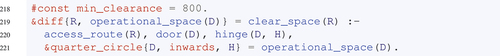
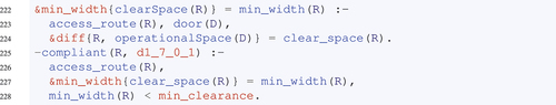
Figure 12. Operational spaces of doors (green regions) and access routes (compliant as gray regions and non-compliant as orange regions) in four distinct scenarios alternating the swing direction and the hinge side.
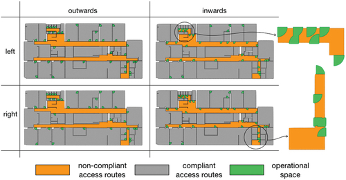
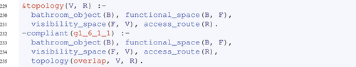
Figure 13. Privacy violations in the NZ building. Functional spaces, visibility spaces, and access routes are, respectively, denoted as yellow, purple and gray regions.
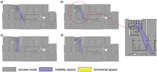
Table 4. Model statistics and runtime performance of Clingo2DSR for checking code compliance on real-world buildings.
Figure 14. 1) a person working from heights, taken directly from (der Bauwirtschaft (BG BAU), Citation2021). 2) movement spaces, fall spaces, and hazard spaces in a building under construction.
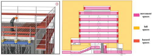
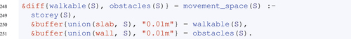
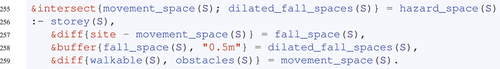
Figure 15. 1) The 13-storey building at timepoint 73 (The second slab quadrant on the second floor is about to be constructed). 2) The generated SVG outputs showing hazard spaces as red regions at time point 73 (a) and at timepoint 75 (b) when the fourth slab quadrant is placed.
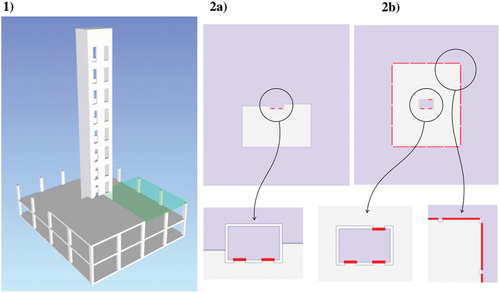
Table 5. Model statistics and runtime performance of Clingo2DSR for construction safety analysis on real-world buildings.
