
Figures & data
Figure 1. Proposed routing protocol.
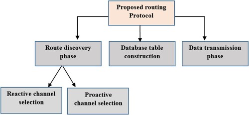
Figure 2. Channel utilization model.
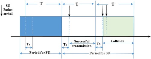
Figure 3. RRQP forwarding (reactive channel selection).
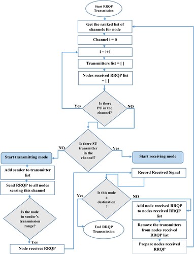
Table 1. The Format of RRQP.
Table 2. Database table attributes.
Figure 4. SU in transmitting mode.
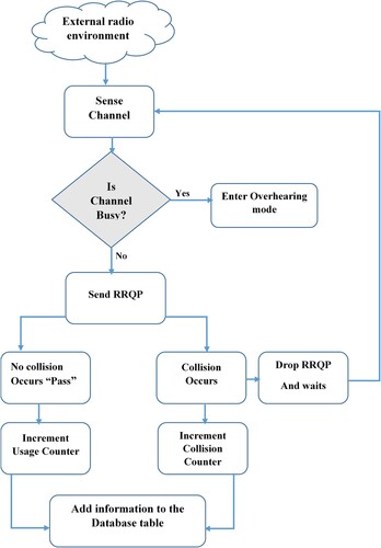
Figure 5. SU in overhearing mode.
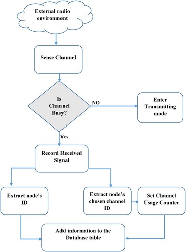
Figure 6. RRQP forwarding (proactive channel selection).
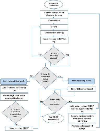
Figure 7. RREP transmission at the destination.
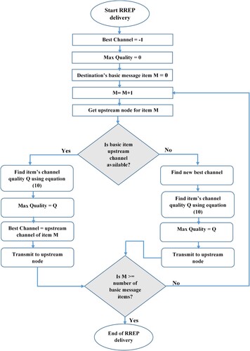
Table 3. The simulation experiments’ parameters.
Figure 8. Throughput vs. number of trials for reactive phase (experiment 1).
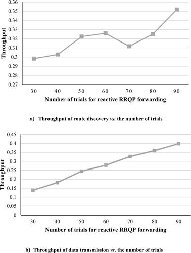
Figure 9. Throughput vs. number of trials for reactive phase (experiment 2).
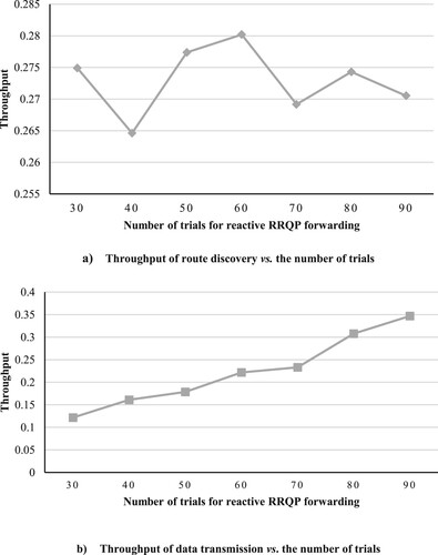
Figure 10. Reactive phase’s throughput vs. number of trials (experiment 3)
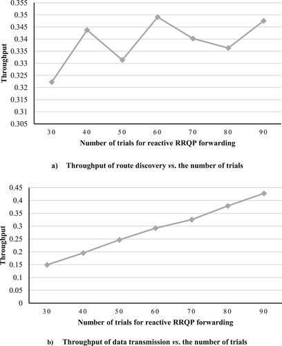
Figure 11. Throughput of route discovery vs. number of channels.
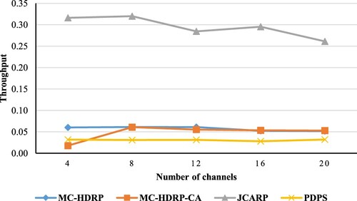
Figure 12. Throughput of route discovery vs. number of nodes.
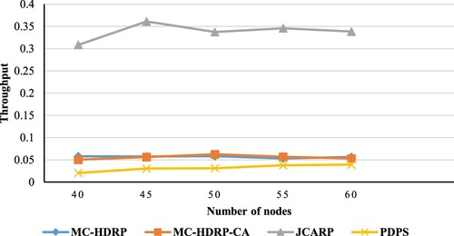
Figure 13. Throughput of route discovery vs. PU transmission range.
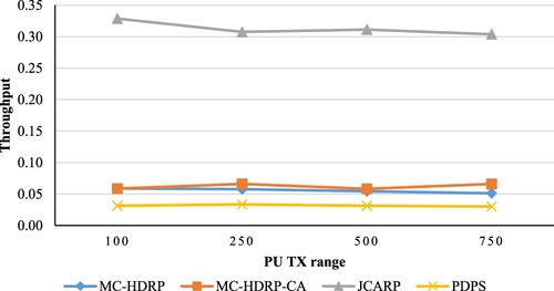
Figure 14. Throughput of route discovery vs. SU transmission range.
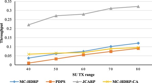
Figure 15. Throughput of route discovery vs. idle probability.
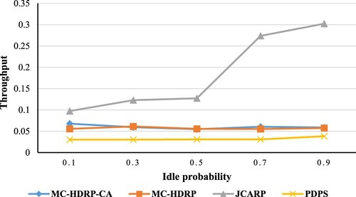
Figure 16. Throughput of data transmission vs. number of channels
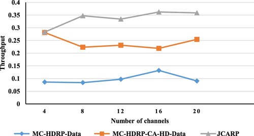
Figure 17. Throughput of data transmission vs. number of nodes.
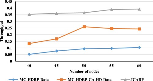
Figure 18. Throughput of data transmission vs. PU transmission range.
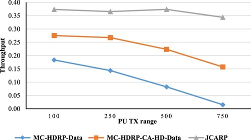
Figure 19. Throughput of data transmission vs. SU transmission range.
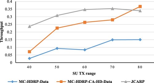
Figure 20. Throughput of data transmission vs. idle probability.
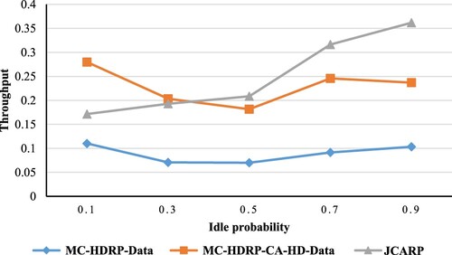
Table A1. Database table of node A.
Table A2. A’s database table after calculating CUC.
Figure A1. Reactive channel selection best case (no collisions).
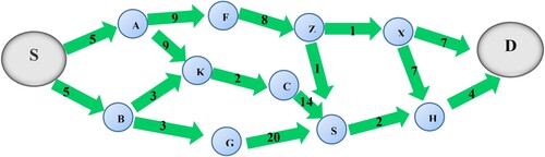
Figure A2. Route discovery moderate case (partial collision).
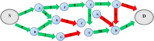
Figure A3. Route discovery worst case.
Table A3. A’s database table after calculating channel usage probability.
Table A4. Final database table of node A.