
Figures & data
Table 1 ASPN Criteria for Quality of Evidence
Table 2 Level of Certainty Regarding Benefit
Figure 1 Anatomy of the SIJ. (a) Posterior-oblique view of the sacrum and iliac bones, ligaments, and nervous supply. SIJ is highlighted in pink overlay. (b) Diarthrodial nature of the SIJ space (pink overlay). The joint consists of an anterior one-third consisting of synovium and posterior two-thirds which is primarily ligamentous. (c) Exaggeration of sacral movement in nutation and counternutation. Original medical illustration by Kamil Sochacki, DO.
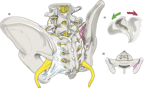
Table 3 Diagnosis of SIJ Pain
Table 4 Conservative Care of SIJ Disorders
Figure 2 Leapfrog Radiofrequency Ablation Technique: A bipolar radiofrequency ablation strategy utilizing two probes placed within 10mm of one another along the SIJ. A lesion is made before moving the superior probe inferior to the second probe. A lesion is made, and the process is repeated with the lead probe being positioned inferiorly once again. Original medical illustration by Kamil Sochacki, DO.
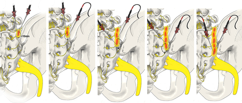
Figure 3 Conventional versus Cooled Radiofrequency Ablation. (a) Conventional RFA requires precise placement of the RFA probe within 1–2 mm of the intended target. Conventional RFA probes can reach temperatures of 100°C and insulating properties prevent heat radiofrequency waves from reaching further target tissue. (b) Cooled RFA needles utilize continuously circulating coolant within a hollow exterior shell to modulate temperature at the tip of the probe to around 60°C. This cooling mechanism avoids charring surrounding tissue, allowing for more effective heat transfer beyond the immediate proximity of the probe tip. The result is a significant difference in the overall size, shape, and area of effect of the ablated lesion, as compared to conventional RFA. Original medical illustration by Kamil Sochacki, DO.
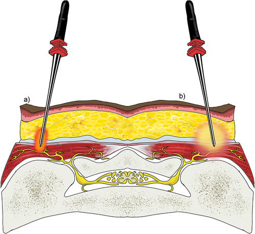
Figure 4 RFA with multilesion probe. This technique utilizes a singular probe which is tunneled through the tissue via a single site to generate a true strip lesion at the SIJ. The probe contains three electrodes creating a combination of monopolar and bipolar lesions. Original medical illustration by Kamil Sochacki, DO.
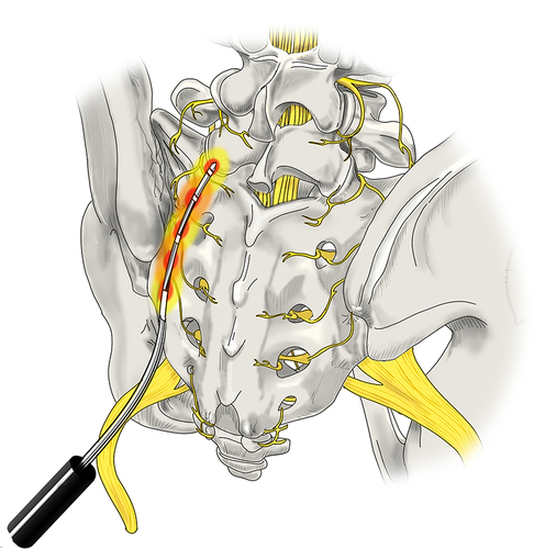
Figure 5 Surgical Techniques: Posterior Allograft Fusion. (a) A large pin (not shown here) is inserted into the joint between the sacrum and the ilium. Next, a tissue dilator and cannula (shown) are inserted to create joint space separation. (b) A rasp is inserted into the cannula to prepare the site for the allograft while decorticating the area. (c) Finally, the allograft which contains the demineralized bone matrix is inserted into the decorticated site to allow for healing and stabilization of the joint. Original medical illustration by Kamil Sochacki, DO.
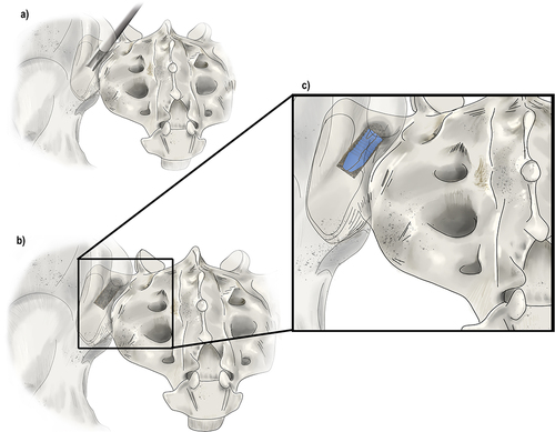
Figure 6 Surgical Techniques: Lateral and Posterior-Oblique Sacral Fusions. (a) The lateral fusion involves the placement of devices across the SIJ from lateral to medial which fixate the ilium and sacrum together. At least two titanium implants are placed through the ilium, or wing bone of the pelvis, across the SIJ, and into the sacrum, the large bone at the base of the spine, to immediately reduce the motion of the joint. This technique involves disruption of musculature. (b) The posterior-oblique approach involves placing implants in a medial to lateral trajectory. The insertion point is the posterior-superior iliac spine which spares dissection of the musculature and minimizes potential injury to other structures. Original medical illustration by Kamil Sochacki, DO.
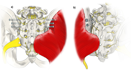
Table 5 Evidence Summary for SIJ Injections
Table 6 Best Practice Recommendations for SIJ Injections
Table 7 Evidence Summary for SIJ Radiofrequency Ablations
Table 8 Best Practice Recommendations on SIJ RFA
Table 9 Summary of Clinical Studies on SIJ Fusion/Stabilization
Table 10 Summary of Adverse Events Reported in the Current Literature