Figures & data
Figure 1 (A) Optical whispering gallery modes in spheres. (B) Resonant frequency shift observed during binding. (C) Polarization of biomolecules in evanescent field.
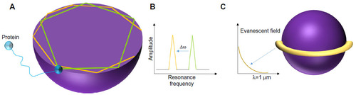
Figure 2 (A) Working principle of a ring resonator. (B) Schematic of solid-phase recombinase polymerase DNA amplification on the resonator.
Abbreviation: IR, infrared.
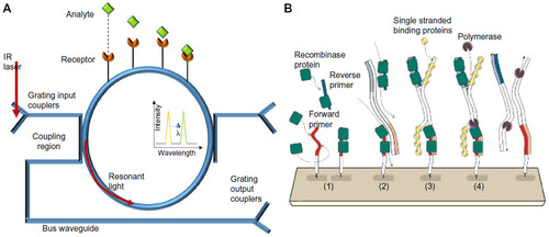
Figure 3 Dual microring resonator optical system.
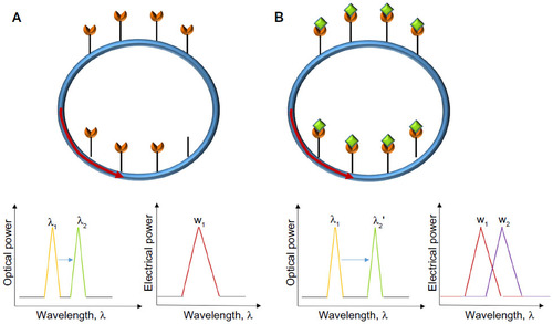
Figure 4 (A) Flow-through microring setup. (B) Comparison of response times using flow-over and flow-through designs.
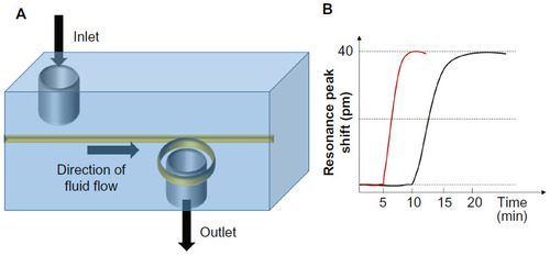
Figure 5 (A) Overview of entire chip with three rolled-up microtubes. (B) Microtube in SU-8 sockets. (C) Optical microtube with ultraviolet light protector caps. Reprinted with permission from.Citation39
Abbreviation: CL, coupling link.
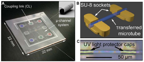
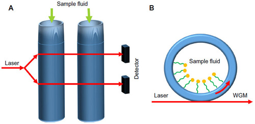
Figure 6 (A) Conceptual diagram of liquid core ring resonators (LCORR). (B) Cross-section of LCORR biosensor.