
 ?Mathematical formulae have been encoded as MathML and are displayed in this HTML version using MathJax in order to improve their display. Uncheck the box to turn MathJax off. This feature requires Javascript. Click on a formula to zoom.
Abstract
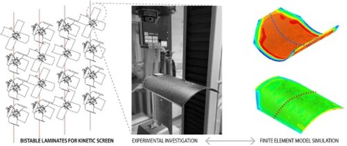
There is an critical need in kinetic envelope design to propose sustainable solutions that can adjust to changing outdoor conditions. Bistable composite laminates are compliant systems appealing for kinetic building envelopes because they present two stable equilibrium states and transition between them with little input energy. This study characterizes the behavior of bistable laminates for kinetic screens by developing an FEA model and conducting experimental testing to validate the model and compare both data sets. The FEA model predicts the laminates’ cured states, snap-through movement, and required actuation force. The FEA model can accurately predict the cured states of the laminates. Regarding the movement of the laminate and actuation force, the simulation results mostly correlate quantitatively with the experimental data and differ qualitatively. However, the FEA model can accurately predict the critical force required to snap through the laminates, which ranges between 2.5 and 4 N.
GRAPHICAL ABSTRACT
Introduction
The kinetic capabilities of some biological and manufactured systems allow them to achieve specific functionalities. For instance, moss plants release spores thanks to the hygroscopic motion of teeth at the openings, and flowers bloom due to the bending of their petals caused by differential strain at the edges (S Poppinga et al. Citation2020). In natural systems, these functionalities are directly connected with environmental conditions, e.g. moss plants only release spores under favourable conditions. The interplay between functionality and environment can be a source of inspiration in creating more energy-efficient systems. Researchers argue that one approach for climate change adaptation is mimicking living organisms’ energy efficiency (Zari Citation2010). Kinetic building envelopes are an example of this approach, responding to changing climate conditions by adjusting their morphology, not unlike living systems, saving energy in the process.
There are many reasons why building envelopes should become more energy efficient. The building sector in the US accounts for around 40% of total energy consumption and associated carbon emissions (Energy Citation2015). Additionally, building envelopes are known to be primarily responsible for buildings’ energy efficiency (Wang et al. Citation2017). Because kinetic envelopes can adjust in response to changing outdoor climate, there is an increasing interest in envelope design to propose sustainable kinetic solutions (Barozzi et al. Citation2016). For example, unlike their static counterparts, kinetic shadings can adjust in response to the solar angles that change throughout the day and year, affecting solar radiation in buildings. Kinetic buildings can be actuated with mechanical actuators and smart materials; however, both have drawbacks. Mechanical actuation typically translates into high consumption of energy (Wang, Beltrán, and Kim Citation2012). Smart materials, however, are difficult to be scaled up into building-size applications due to low strain or large actuation timeframes (Simon Poppinga et al. Citation2018). Nevertheless, smart materials can be combined with compliant mechanisms to amplify deflections and shape-change for kinetic building envelopes.
Compliant systems have recently received renewed attention as an alternative to rigid mechanical actuation mechanisms for kinetic envelope design. Compliant mechanisms show deployability or shape change derived from the material flexibility of their members (Howell Citation2013). The advantages of using compliant versus rigid kinetic systems can be summarized in the following: their ability to adapt to complex shapes and the simplicity of their mechanisms. Because conventional shading devices such as Venetian blinds and roller shades are based on modular grids, they are typically harder to adjust to free-form envelopes, which are increasingly common in contemporary architecture (Barozzi et al. Citation2016). Moreover, these rigid mechanisms for kinetic shades typically have many components, resulting in elevated assembly and maintenance costs (Poppinga et al. Citation2016). Compliant mechanisms, in contrast, can be adapted to non-planar envelopes and have simple hinge less kinetic systems. In nature, compliant mechanisms are omnipresent; however, most motile plant structures rely on passive hydraulics alone, which renders large timescales (Poppinga et al. Citation2020). Elastic instability, however, allows for speeding up kinetic transformation with structures that can be prestressed.
Recently, researchers have sought to incorporate elastic instability, also described as buckling, into kinetic envelope design. In a study, researchers developed shading modules driven by both buckling of thin plates and torsional buckling of slender frames (Khezri, Hu, and Rasmussen Citation2022). The thin plates are bistable beams that are simply supported at each end and have their ends shortened; when subjected to a transverse force, they can transition from one to their other stable state. The mechanisms developed were simulated using finite element modelling to test the feasibility of the prototypes and optimize the design for greater aperture. A second study by the authors proposes a series of buckling mechanisms that allow passive cooling and heating applications, and ventilation (Khezri and Rasmussen Citation2022; Khezri, Hu, Luo et al. Citation2022). In addition, they explore the use of a smart material, Shape Memory Alloys (SMAs) to actuate one of the designs. The work developed shows the potential of using small buckling core units that generate large deflection in additional members, and how bistable mechanisms can facilitate the design of devices that switch between an opened and closed state. Other examples of elastic instability in envelope design include a snapping façade shading system composed by snapping polystyrene beams and a folding Miura-ori membrane (Song, Heo, and Shim Citation2018).
Bistable composite laminates are compliant systems that have received significant research focus in recent decades. A bistable composite laminate is a thin plate or shell structure composed of an unsymmetric composite laminate. It is unique because it can exist in either one of two different stable equilibrium states (Dano and Hyer Citation1998). As the laminate cools down from the curing process, it develops curvature due to residual thermal stresses induced by the difference in thermal expansion properties through its thickness. Above a critical length-to-thickness ratio, the laminate stabilizes in one of two approximately cylindrical equilibrium states and can switch to another stable state via a snap-through actuation (Cantera et al. Citation2015). Due to their multiple stable states and snap-through behaviour, bistable composite laminates have attracted considerable attention in morphing structures (Zhang et al. Citation2019) and energy harvesting (Emam and Inman Citation2015). A particular focus has been on using smart materials to actuate the bistable laminate from one stable state to the other. Actuation methods investigated thus far include piezoelectric actuation (Arrieta et al. Citation2013), shape memory alloy actuation (Kim et al. Citation2014), and thermal actuation (Lele et al. Citation2019).
This research forms part of a larger research agenda to develop and optimize a bistable kinetic screen actuated with smart materials. The bistable screen comprises several kinetic units that form a tessellation for a building skin that can be placed in windows and skylights for daylight control. Besides the structural holder, the three elements of each unit are the bistable laminates, the strings that pull into the laminates, and the shape memory alloys used for actuation. This paper focuses on characterizing the behaviour of bistable composite laminates for the proposed kinetic screen design by developing an FEA model and experimental testing. The model is developed to characterize the cured state of the laminate and the snap-through movement of the laminate and its required actuation force. The model settings include the boundary conditions of the kinetic device and the linear force used to pull the laminates into their open position. A linear force is assumed to actuate the bistable laminates; Further details of the mechanisms of the shading device appear in the following section. We conducted an experimental study to validate the model and compared both data sets thereafter. The ultimate goal in creating the model is to find adequate configurations for the actuation mechanism design that decreases the force needed to snap through and to select the appropriate Shape Memory Alloy to actuate the bistable laminates.
Methods
The study aimed to model and characterize the behaviour of bistable laminates used for a kinetic shading screen that can open and close. The screen is designed to be placed behind window openings, allowing indoor daylight control. The screen comprises holder units that are tessellated to adapt to different surfaces, as shown in Figure (A). Because the bistable laminates are very thin (∼0.3 mm), the holder unit is lightweight and attached to very thin rope wires (Ø 4 mm). The holder unit comprises four bistable flaps, strings that pull into them to snap through and snap back, and shape memory alloy actuators. The strings’ angle and attachment point to the bistable laminate is critical to the resulting actuation force required to force the laminates to transition between their stable states. The Shape Memory Alloy (SMA) used to actuate the holder unit has both an SMA spring and a biasing spring, which pushes the SMA back into position after actuation. Commercially available SMAs have a variety of force ratings; thus, finding the critical force to snap the laminates is of tremendous importance.
Figure 1. (A) Bistable kinetic screen. (B) Detail of a single unit of the screen.

The four bistable laminates are 140 × 180 mm, made with two plies of unidirectional carbon fibre arranged at a 0°90° configuration. The bistable flap is fabricated using the method described by (Lele et al. Citation2019), which includes three main steps. First, the prepregs are cut into shapes and placed over an aluminum plate with the specified angle. The second step is to assemble a vacuum bag with a perforated plastic sheet, a polyester sheet, a breather fabric, and a stretchy vacuum bag film. The third step is to put the vacuum bag into the oven and cure the samples under a vacuum with a pump. The heating up to 120 °C and slow cooling down process induces internal thermal stresses into the laminate. As a result, the laminates coming out of the vacuum bag already exhibit one of the two stable states. The size of the laminates is determined by the screen design and proposed tessellation. For further discussion on the design and technical considerations of the screen, readers can refer to (Vazquez and Duarte Citation2022; Vazquez et al. Citation2023). Table shows the geometric and material properties of the bistable flaps. The tensile properties of the composite were obtained using the standard characterization test D3039/D3039M. These properties are the ones used in the FEA model. Due to stress relaxation of the laminates, we conducted the snap-through tests a week after fabrication.
Table 1. Laminate properties.
The experimental study was carried out to measure the curvature of the laminate and primarily, to measure the force required to snap through the composites. To measure the curvature of the composites, side view pictures were taken of the samples and then ImageJ was used for image processing and measurement. While the holder unit design has two strings per composite laminate, we only measured the force required to snap through, not snap back. In other words, the force required to transition the laminates into their opened position, as shown in Figure . This is because a preliminary study showed that the force required to snap back (close) is ∼1.2 N, much less than the force required in the other direction. Therefore, this study focuses on the snap-through of the laminates, which is critical to reducing the SMA linear actuators’ force requirement and decreasing the count of SMA actuators. For instance, if two bistable flaps can be actuated with a single SMA actuator, that would translate into a more efficient and affordable system with less material consumption.
An MTS machine was used to measure the force required for the laminates to snap-through. Figure shows the experimental setup using the test jig attached to a 10M load cell. The test jig was fabricated for the purpose of this study with several string paths to test, as shown in Figure (B). Figure depicts the different string paths with 9 possible combinations between positions Z (52, 62, and 72 mm) and X (116, 106, and 96 mm). According to the screen design, the bistable flap sits on the test jig, with a single attachment point to the jig. Studies were conducted by pulling the load cell with the test jig up with the string attached to the lower MTS gripper. The rate selected for the study was 1 mm per second. The study was conducted at least three times per configuration. The experimental setup of the study reflects the holder unit design, with different string paths to test to compare the obtained data with an FEA model. The study was constrained to the existing holder unit design; a limited number of X and Z alternatives were tested according to string paths possible within the defined holder unit design.
Figure 2. (A) Experimental setup. (B) Test jig.

Figure 3. (#A) Bistable laminates’ dimensions and name convention. (B) FEA model of the bistable composite laminate.

To find adequate string path configuration, we conducted experimental tests and FEA studies using different positions in the Z and X axis of the holder unit. The FEA model was developed using the commercial FEA software packaged ABAQUS CAE and is presented in Figure . The geometry of the laminate, as illustrated in Figure , is represented by a 2D surface that intersects the midplane of the laminate. On the other hand, the string is modelled as two wire features sharing a common node situated at the z-position pivot point of the test rig. The laminate is discretized using linear reduced integration S4R shell elements, with a global element size of 4 mm. This mesh results in a total of 1235 elements and 1315 nodes. The utilization of S4R shell elements in this investigation is based on their well-established robustness for analyzing bistable composites with ABAQUS, as demonstrated in prior research (Iqbal and Pellegrino Citation2000). A mesh convergence study determined that an element size of 4 mm achieves the necessary accuracy and computational efficiency. Conversely, slipring connector elements with linear elastic behaviour are employed to discretize the string. For the composite material's constitutive model, a linear elastic material model is assumed. The laminate is assigned a composite section with a stacking sequence of [0/90]T to define its laminate properties. In its initial state, the clamp region of the laminate is fixed in all six degrees of freedom (DOFs), effectively simulating the clamp conditions at the laminate's end. The pivot point of the string is constrained in all three translational DOFs, while the free end of the string is restricted in both in-plane translations, allowing only vertical translation. Zero material flow is also imposed on the slipring connector elements of the string. Lastly, a uniform temperature field is applied to the laminate, with a temperature of 120 °C, in order to replicate the conditions during the curing process.
The snap-through behaviour of the bistable laminate is simulated through the use of two coupled models. Initially, a linear eigenvalue analysis is conducted to predict the linear buckling modes of the laminate after cooling down following the curing process. Subsequently, these predicted buckling modes are incorporated as imperfections in a quasi-static dynamic implicit analysis, which simulates a displacement-controlled force-displacement test performed on the laminate after it has cooled down from cure. This coupled procedure is necessary to reproduce the multi-stage snap-through phenomenon observed during experimental tests.
The buckling model comprises three initial steps, all of which are static implicit analyses. These steps aim to simulate the cooling of the laminate from the curing process and to apply a unit force to initiate the buckling mode analysis. Initially, the uniform temperature field applied to the laminate is adjusted to 20 °C, thereby emulating room temperature conditions. This adjustment induces a temperature change of −100°C, resulting in thermal strains and subsequent development of residual thermal stresses within the laminate. Consequently, the laminate undergoes curved deformation, leading to its bistability. Temporary displacement constraints are applied to ensure convergence to the closed stable state of the laminate. In the subsequent step, these temporary displacement constraints are removed, allowing the laminate to relax into its closed stable state. The third step involves the application of a unit force in the downward direction at the free end of the string. The final step performs a linear buckling analysis to identify the first five buckling modes of the laminate.
Regarding the force-displacement model, the initial two steps mirror those of the buckling model, simulating the development of curvature of the laminate following the cooling process. The predicted buckling modes are introduced as imperfections during the initial step of this model. In the third step of the force-displacement model, a dynamic implicit analysis incorporating quasi-static numerical damping is performed to simulate the actuation of the laminate. Here, a displacement of −28 mm is gradually applied to the free end of the string over a period of 28 s. The automatic time stepping scheme is limited to a maximum time step of 1 s, replicating the displacement rate of 1 mm per second observed in the experimental tests. In the final step of the model, the displacement constraint at the free end of the string is removed, enabling the laminate to relax into its open stable state.
Results
This study aimed at characterizing the behaviour of bistable laminates for a kinetic shading screen using FEA modelling and experimental testing. Recall that the samples were fabricated with two layers of unidirectional carbon fibre prepregs with fibres in 0,90 degree orientations, respectively, as shown in Figure (A). The FEA model simulates the heating up and cooling down of the composite laminates, the process depicted in Figure (C), starting with a planar composite, and finishing with a curved laminate as a result of the thermal stresses. The two stable states represent the opened and closed positions of the kinetic system. Figure (B) compares the laminates’ cross section for the FEA model and measured from the bistable samples. As shown in the graph, the FEA model can accurately predict the cured state of the composite laminates, in both State 1(opened) and State 2 (closed). The curvature difference between the experimentally measured and the FEA model is less than 5%, which is an acceptable margin of error.
Figure 4. (A) Composite laminate fibre stacking configuration. (B) Comparison between experimental and FEA cross section of the laminates. (C) Cooling down the composite laminate in the FEA model.

Simulation and experimental data were collected to study the effect of different string paths that pull into the bistable laminates forcing them to snap through to their open position. Figure (A) compares the FEA simulation results with the experimental results for A12, A22, and A23, which all have the string path in position X = 106 mm and different Z positions. Note that there is an overall consistency between the different experimental tests conducted. A difference between the experimental and simulated force curve is that the FEA model predicts the transition of the laminates happening in a shorter time frame than the measured time. An interesting aspect of the graph is the correspondence between the peak force required to snap the bistable laminates; There is no significant difference between the highest peak force required. The graph also shows that the laminates snap into their open state in multiple stages. The peak force occurs when regions of the laminate closer to the attachment point start transitioning into the second state. The steps to the right side of the curves’ peak are primarily evident in the experimental data; however, we can also see them in the FEA curve, albeit less apparent.
Figure 5. Experimental results vs. FEA for Z = 72(A1, A2, A3). Experimental results for X = 96 (B1). Experimental results for X = 106 (B2). Critical load all configurations FEA vs. Experimental average (C).

Figure (B) compares simulation data with experimental data for the same X value and different string paths’ Z value. Overall, we can observe that the force required to snap the laminates open decreases as the z value increases. This trend is observed in both the predicted and measured values. Interestingly, the morphology of the force vs. time curve is not different across the different simulated FEA results. However, we can see two different curve morphologies for the measured data: one with two steps until the peak force is reached and another with a single step before the curve. The difference in morphology in the measured curves might be related to the experimental settings, where the string pulled by the load cell might encounter some unexpected friction which causes the jumps in force required. Figure (C) compares the peak force required for the laminates to snap through into their open position. In general, the FEA model is able to predict the peak force required to snap open the bistable laminates for most of the string-path configurations. A noticeable exception is A31(X = 116, Z = 52) which stands out in the graph as having a significant difference in predicted vs. measured. Table compares the peak force values for FEA and experimental results. Note that the errors are within 15% with the mentioned outlier (A31), which presents an error of 23%.
Table 2. Experimental vs. FEA critical load.
Discussion
The FEA model can accurately predict the cured shape of the bistable laminates within a 5% margin of error. The FEA model can consequently be used as a design tool to test different laminate configurations in terms of fibre orientation, layer count, and others. To be able to measure the required critical snap-through force, simulating the cooling down of the laminates that imprint the bistable behaviour is a necessary step in the FEA model.
The results show a significant change in critical snap-through load for the different string-path configurations or actuation points. The critical load increases as the Z distance decreases, the lower Z value requiring at least 0.5 N more force to cause snap-through. The critical load increases as the X distance increases; however, the difference between the two extremes accounts for no more than 0.3 N. The results suggest that we can increase the Z value to decrease the actuation force for the bistable laminate. Decreasing the actuation force is beneficial to decrease the energy requirements of the system.
Comparing the predicted and measured data shows that the FEA model can predict the force required to snap through the bistable laminates, particularly quantitatively (Table ). The force vs. time curves are in high correspondence quantitatively but not so much qualitatively. The shape of the force curve and the time difference between them are the two significant qualitative differences. The stated difference between predicted and measured data might be related to model sensitivity regarding material properties, the assumption of linear elastic material behaviour, boundary conditions and the bistable laminates’ sensitivity to fabrication conditions such as curing temperature and humidity. Nevertheless, for the purpose of this study, which is to construct an FEA model that can help design a kinetic bistable device, the results obtained are sufficient to provide the necessary insights to design the actuation mechanism. The results allow us to quantify the amount of force to design the actuation mechanisms for the bistable kinetic system. In other words, while the actuation time might differ from the predicted, the amount of force required to actuate the system will be close to the predicted. Future work could investigate the causes of the qualitative differences in the experimental and FEA force response curves, with features such as friction at the pivot point and nonlinear elasticity of the string added to the FEA model.
The results show that 2.5–4.5 N is necessary to cause the bistable laminates to snap through. Shape-memory alloys that are commercially available are within the 3–10 N range – For example, those provided by Next Metal corporation or Kellogg's Research Lab. It is, therefore, preferable to select the string paths below 3 N for this particular case study to ensure that the linear actuator can snap the laminates into their opened position. For instance, the A11 and A12 configurations have low actuation force requirements and thus are preferable for the kinetic bistable device. Further optimizations could be conducted to decrease the actuation requirements even more with the FEA model.
Conclusion
This study aimed to characterize the behaviour of bistable laminates used in a kinetic shading system. In particular, the aim was to assess the force required to open and close the laminates and develop an FEA model that can accurately predict the force requirements. For this purpose, we collected experimental data and compared it to simulation data for both the cured shapes of the laminates and the snap-through critical force. The FEA model developed can accurately predict the cured shapes of bistable laminates. In addition, we experimentally tested different actuation points (string paths) and compared them to the developed FEA model. The simulation results mostly correlate quantitatively with the experimental data and differ qualitatively. The qualitative differences most likely stem from the nonlinear elasticity of the string added to the FEA model. However, the FEA model can predict the critical force required to snap through the laminates, which is relevant to selecting an actuation mechanism.
The study was limited to defined actuation points for the bistable laminates, and only composite laminates with a single dimension were tested. Another limitation was that we did not model the SMA wires in the finite element study; The reason being that we wanted to predict the snap-through force to find adequate SMA actuators. Nevertheless, the results indicate that the FEA model can accurately predict the critical snap-through force, which can be used to predict other laminate sizes and layup configurations. A natural progression of this work is to conduct an optimization study for the laminates’ actuation point to decrease critical force requirements, given the constraints required from the intended application. The study's main contribution is characterizing the mechanical behaviour of bistable laminates for lightweight and energy-efficient kinetic building screens.
Data availability statement
The data that support the findings of this study are available from the corresponding author upon reasonable request.
Disclosure statement
No potential conflict of interest was reported by the author(s).
References
- Arrieta, A. F., O. Bilgen, M. I. Friswell, and P. Ermanni. 2013. “Modelling and Configuration Control of Wing-shaped Bi-stable Piezoelectric Composites under Aerodynamic Loads.” Aerospace Science and Technology 29 (1): 453–461. https://doi.org/10.1016/j.ast.2013.05.004.
- Barozzi, M., J. Lienhard, A. Zanelli, and C. Monticelli. 2016. “The Sustainability of Adaptive Envelopes: Developments of Kinetic Architecture.” Procedia Engineering 155:275–284. https://doi.org/10.1016/j.proeng.2016.08.029.
- Cantera, M. A., J. M. Romera, I. Adarraga, and F. Mujika. 2015. “Modelling and Testing of the Snap-through Process of Bi-stable Cross-ply Composites.” Composite Structures 120:41–52. https://doi.org/10.1016/j.compstruct.2014.09.064.
- Dano, M.-L., and M. W. Hyer. 1998. “Thermally-induced Deformation Behavior of Unsymmetric Laminates.” International Journal of Solids and Structures 35 (17): 2101–2120. https://doi.org/10.1016/S0020-7683(97)00167-4.
- Emam, S. A., and D. J. Inman. 2015. “A Review on Bistable Composite Laminates for Morphing and Energy Harvesting.” Applied Mechanics Reviews 67 (6). https://doi.org/10.1115/1.4032037.
- Howell, L. L. 2013. “Compliant Mechanisms.” In 21st Century Kinematics: The 2012 NSF Workshop, edited by J Michael McCarthy, 189–216. London: Springer.
- Iqbal, K., and S. Pellegrino. 2000. “Bi-stable Composite Shells.” In 41st Structures, Structural Dynamics, and Materials Conference and Exhibit, April. AIAA 2000-1385.
- Khezri, Mani, Y. Hu, Q. Luo, M. R. Bambach, L. Tong, and K. J. R. Rasmussen. 2022. “Structural Morphing Induced by Functionalising Buckling.” Thin-Walled Structures 181:110103. https://doi.org/10.1016/j.tws.2022.110103.
- Khezri, Mani, Y. Hu, and K. J. R. Rasmussen. 2022. “Novel Shading Modules with Buckling as Driver for Shape Morphing.” Thin-Walled Structures 181:109941. https://doi.org/10.1016/j.tws.2022.109941.
- Khezri, M., and K. J. R. Rasmussen. 2022. “Functionalising Buckling for Structural Morphing in Kinetic Facades: Concepts, Strategies and Applications.” Thin-Walled Structures 180:109749. https://doi.org/10.1016/j.tws.2022.109749.
- Kim, S.-W., J.-S. Koh, J.-G. Lee, J. Ryu, M. Cho, and K.-J. Cho. 2014. “Flytrap-inspired Robot Using Structurally Integrated Actuation Based on Bistability and a Developable Surface.” Bioinspiration & Biomimetics 9 (3): 036004. https://doi.org/10.1088/1748-3182/9/3/036004.
- Lele, A., V. Deshpande, O. Myers, and S. Li. 2019. “Snap-through and Stiffness Adaptation of a Multi-Stable Kirigami Composite Module.” Composites Science and Technology 182 (May): 107750. https://doi.org/10.1016/j.compscitech.2019.107750.
- Poppinga, S., D. Correa, B. Bruchmann, A. Menges, and T. Speck. 2020. “Plant Movements as Concept Generators for the Development of Biomimetic Compliant Mechanisms.” Integrative and Comparative Biology 60 (4): 886–895. https://doi.org/10.1093/icb/icaa028.
- Poppinga, Simon, A. Körner, R. Sachse, L. Born, A. Westermeier, L. Hesse, J. Knippers, M. Bischoff, G. T. Gresser, and T. Speck. 2016. “Compliant Mechanisms in Plants and Architecture.” In Biomimetic Research for Architecture and Building Construction, edited by Jan Knippers, Nickel Klaus, and Thomas Speck, 69–193. Cham: Springer.
- Poppinga, Simon, C. Zollfrank, O. Prucker, J. Rühe, A. Menges, T. Cheng, and T. Speck. 2018. “Toward a New Generation of Smart Biomimetic Actuators for Architecture.” Advanced Materials 30 (19): 1703653. https://doi.org/10.1002/adma.201703653.
- Song, J. Y., S. Heo, and J. Shim. 2018. “Snapping Facades: Exploring Elastic Instability for the Building Envelope.” Technology Architecture and Design 2 (1): 45–54. https://doi.org/10.1080/24751448.2018.1420964.
- United States Department of Energy. 2015. "Quadrennial Technology Review: An Assessment of Energy Technologies and Research Opportunities.” USA: Department of Energy.
- Vazquez, Elena, Julio Diarte, and Jose Duarte. 2023. “Kinetic Shades: Designing a Shape-Morphing Device with Bistable Laminates and Shape Memory Actuators.” Journal of Architectural Engineering 29 (4). https://doi.org/10.1061/JAEIED.AEENG-1646.
- Vazquez, Elena, and Jose P Duarte. 2022. “Bistable kinetic shades actuated with shape memory alloys: prototype development and daylight performance evaluation.” Smart Materials and Structures 31 (3): 034001. https://doi.org/10.1088/1361-665X/ac5014.
- Wang, J., L. O. Beltrán, and J. Kim. 2012. “From Static to Kinetic: A Review of Acclimated Kinetic Building Envelopes.” Proceedings of the Solar Conference 5:2029–4022.
- Wang, Y., J. Kuckelkorn, F.-Y. Zhao, H. Spliethoff, and W. Lang. 2017. “A State of Art of Review on Interactions between Energy Performance and Indoor Environment Quality in Passive House Buildings.” Renewable and Sustainable Energy Reviews 72:1303–1319. https://doi.org/10.1016/j.rser.2016.10.039.
- Zari, M. P. 2010. “Biomimetic Design for Climate Change Adaptation and Mitigation.” Architectural Science Review 53 (2): 172–183. https://doi.org/10.3763/asre.2008.0065.
- Zhang, Z., Y. Li, X. Yu, X. Li, H. Wu, H. Wu, S. Jiang, and G. Chai. 2019. “Bistable Morphing Composite Structures: A Review.” Thin-Walled Structures 142:74–97. https://doi.org/10.1016/j.tws.2019.04.040.