
 ?Mathematical formulae have been encoded as MathML and are displayed in this HTML version using MathJax in order to improve their display. Uncheck the box to turn MathJax off. This feature requires Javascript. Click on a formula to zoom.
Abstract
This paper describes a new approach to control stall and surge instabilities in the compressor system by using of finite time backstepping-based adaptive sliding mode method. The most important innovation of this study is to provide a finite time adaptive control method to simultaneously prevent the stall and surge instabilities in a compressor system in the presence of disturbance and uncertainty in the compressor characteristic curve as well as the throttle valve. The disturbance and uncertainty issues are covered by a robust sliding mode control and the gain coefficients of this controller as well as the estimation of uncertain terms are obtained by using the adaptive method. The Lyapunov stability criterion is used to evaluate the finite-time stability of the closed-loop system. The performance of the proposed method is compared with other literature methods through simulation in Matlab. The simulation results show that the proposed controller is better than the existing methods in terms of surge preventing and robustness against uncertainty and disturbance.
KEYWORDS:
1. Introduction
With the advancement of technology, compression systems have been considered by many scientific and industrial communities due to their usefulness. Compressors are widely used in many industries such as oil and gas, petrochemicals, aerospace, power plants, etc. to increase pressure or transfer fluid and play an important role in key parts of the industry so that any malfunction of this equipment can cause the failure of upstream and downstream equipment. Therefore, due to the high importance of compressors in the industry, extensive efforts have been made to improve the reliability, stablity, and optimal performance of these systems [Citation1–5].
Phenomena limiting the performance of the compressor are: surge, rotating stall, and choke. Rotating stall is a local disruption of flow inside the compressor which carry on to deliver compressed flow, but with decreased effectiveness. The instability of the surge is the most destructive phenomenon, because it can cause severe mechanical damage to this machine and take it out of service [Citation6]. Surge and stall phenomena are two dynamic instabilities that occur in compressor systems of both axial and centrifugal types. Surge instability can influence the complete compression system, and such as a limit cycle, it is categorized by dangerous oscillations in the compressor’s pressure and flow leading to a considerable loss in the productivity and performance of the system.
Due to the damaging effects of surge and stall instabilities on compression systems, extensive efforts have been made to control these instabilities in centrifugal compressors. The two main categories of surge instability control include surge avoidance and active surge control [Citation7,Citation8]. In the surge avoidance method, by selecting the surge control line and designing the controller, an attempt is made to prevent the system from entering the unstable zone. This method is widely used in industry, but system efficiency is sacrificed for stable performance. The active control method proposed by Epstein [Citation8] deals with the issue of active surge stabilization, but this method has not much industrial application and several works with different control methods and actuators have been presented in this field [Citation9–13]. Because of drawbacks of using surge avoidance methods that reduce compressor efficiency, active control method has emerged as an effective tool to overcome surge instability. The active controller may enhance the stable performance of the compressor system through (1) enriched aerodynamic design, (2) reduction of changes in working conditions, (3) consideration of components affecting the flow and (4) active suppression of aerodynamic instabilities.
Recently, many efforts have been made in this field to control surge and stall instabilities in constant and variable speed compressors due to the advantages of active control method in reducing losses and increasing the efficiency of the compressor system. Articles [Citation14,Citation15] have used the feedforward method to control the compressor pressure and subsequently control the compressor surge in the presence of disturbance and uncertainty. For the above-mentioned control purposes, backstepping and adaptive methods have been used in [Citation16–18]. The issue of stall and its control has been comprehensively studied in [Citation19–21], and various control methods have been proposed in the field [Citation22,Citation23]. However, there are still doubts about the ability of existing controllers on several issues.
Also, a comprehensive study on the instabilities of surge and stall has been done in [Citation24]. Despite the significant advances in the design of the controller of the above instabilities, there are still several obvious and annoying shortcomings and weaknesses which are:
In the control methods designed to date, the problem of stall and its control is considered as a different and separate problem, while due to the effect of stall instability in the onset of the surge phenomenon, simultaneous consideration of these two phenomena in the design of the controller is mandatory.
Considering the characteristic curve of the compressor in a certain way is an assumption with a high probability of error, because using the compressor in the compression system and its effectiveness from different parts such as upstream and downstream equipment, pipe, and various parameters, this characteristic curve is always uncertain.
Not considering the disturbances on the flow and pressure in addition to uncertainty on throttle valve are other shortcomings of many previous studies in this field.
Despite the importance of using finite-time methods with high convergence rates for different applications [Citation22–27] and the need to pay attention to these methods to control surge due to the destructive effects of its occurrence and persistence, no specific efforts have been made to finite-time control of surge to date.
In general, the organization of this paper is as follows: In Section 2, the dynamic model of the compressor system covering surge and stall instabilities is presented. In Section 3, the planned controller is presented. Finally, the simulation results and conclusions are presented in Sections 4 and 5 of the paper.
2. Model of the compressor system
Comprehensive studies have been performed for compressor modelling to accurately describe the behaviour of the compressor system and the controller design. References [Citation35–37] provide a complete overview of compressor system modelling methods. The most important division of the proposed models is based on the dimension. One-dimensional models are able to describe surge instability, while two-dimensional models can predict both surge and rotating stall instabilities in compressor system behaviour. Despite many efforts to date, the Moore-Gritzer model introduced in 1986 is the most widely cited model for controller design in centrifugal compressor systems [Citation38]. The model is able to qualitatively describe the behaviour of the compressor system and despite its simplicity, describes well the relationship between the parameters of the model and their effects on the dynamics of the overall system. This model is a control-oriented model using first-order differential equations and has a good computational complexity. In this paper, the capabilities of this model have been used to design surge and stall instabilities controller. Now we will describe the mentioned model. The dynamic equations governing the compressor system are:
(1-a)
(1-a)
(1-b)
(1-b)
(1-c)
(1-c)
In the above equations, and
represent the increase in pressure and mass flow of the compressor, respectively.
signifies rotating stall and
indicates dimensionless time,
denotes the characteristic of the compressor curve and
represents the characteristic of the throttle valve.
specifies the length of the compressor and ducts and
is a constant coefficient.
is the Gritzer parameter and is obtained from the following equation:
(2)
(2) In the above equation,
is the constant related to the tangential speed of the compressor,
is the speed of sound,
represents the volume of the plenum, and
is the cross section of the compressor.
The normalization of the equations of the constant speed compressor system is done using the following equation:
(3)
(3) where
is the flow rate and
is the pressure difference.
Using normalization, a class of compressor curves is mapped to a single characteristic curve for each speed. The characteristic curve defines the nonlinear connection between the compressor pressure and flow
. Following Moore and Gritzer [Citation38,Citation39], the cubic characteristic curve of the compressor is described as follows:
(4)
(4) where
is the value of the characteristic curve in 0 dB.
indicates the half-height and
specifies the half-width of the characteristic curve.
According to [Citation18], the throttle valve characteristic is specified by:
(5)
(5) where
is the valve’s yield.
The presence of disturbances in the compressor system affects the stability and performance of the active controller of surge and stall. In this model, the compressor flow and pressure disturbances are as follows:
(6-a)
(6-a)
(6-b)
(6-b)
(6-c)
(6-c)
Following Moor and Greitzer in Imani et al. [Citation40], Figure exhibits a plan of a compression system with a closed coupled valve (CCV). By means of CCV as a control actuator, the dynamic equations of the compressor system are:
(7-a)
(7-a)
(7-b)
(7-b)
(7-c)
(7-c)
is the control input for the system. Considering
,
and
, the compressor state space equations will be equal to:
(8-a)
(8-a)
(8-b)
(8-b)
(8-c)
(8-c) The equations governing the compressor system show that the flow disturbance is in the form of unmatched while the disturbance in the pressure is of the matched type.
3. Robust finite-time adaptive sliding mode control for stall and surge instabilities
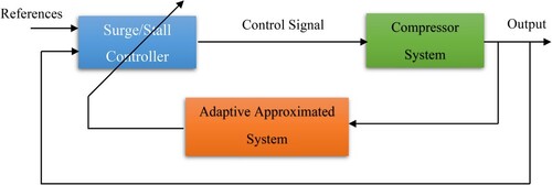
In this section, a novel finite-time adaptive sliding mode control structure is presented to control stall and surge instabilities. To prove the stability through Lyapunov method, we have used the backstepping method to suitably define the error. The upper bounds of uncertainty on the throttle valve and uncertainty on the compressor characteristic curve are considered unknown. The proposed controller is able to actively manage stall and surge instabilities despite the effects of uncertainties and disturbances mentioned above. The controller schematic is shown in Figure .
Figure 1. The compressor system with CCV actuator [Citation40].
![Figure 1. The compressor system with CCV actuator [Citation40].](/cms/asset/503771be-0ebf-4001-86a0-73f94297ff27/taut_a_2329503_f0001_oc.jpg)
Figure 2. Schematic of finite-time adaptive sliding mode control.
Now we will describe the controller design steps. The state space equations of the compressor system are considered as follows:
(9-a)
(9-a)
(9-b)
(9-b)
(9-c)
(9-c)
By defining the error as follows
(10-a)
(10-a)
(10-b)
(10-b)
(10-c)
(10-c) where
and
are virtual control functions. The dynamic equations of the error are achieved as follows
(11-a)
(11-a)
(11-b)
(11-b)
(11-c)
(11-c) Let’s define the functions
with the condition
as (28), where
are the unknown upper bound of these functions.
(12-a)
(12-a)
(12-b)
(12-b)
(12-c)
(12-c) By rewriting the error dynamic equations:
(13-a)
(13-a)
(13-b)
(13-b)
(13-c)
(13-c) To prove stability, we candidate the following Lyapunov function:
(14)
(14) where
(15)
(15) where
are estimators for
. It is obtained by derivation from Lyapunov function:
(16)
(16) Now select the control rules as follows:
(17-a)
(17-a)
(17-b)
(17-b)
(17-c)
(17-c) where
are positive parameters of the controller gain.
It is obtained by replacing the control rules in the derivative of Lyapunov’s function
(18)
(18) It is obtained by simplifying the Equation (18) as:
(19)
(19)
(20)
(20)
(21)
(21)
Select the adaptive rules for estimating as follows:
(22)
(22) where
are adaptive tuning parameters.
By substituting adaptive rules in Equation (21) is obtained.
(23)
(23) Equation (23) ensures system stability. Now we prove that the designed controller is finite-time.
Definition 1
[Citation41]. Assume a nonlinear time-invariant system as:
(24)
(24) where
is a continuous vector function on an open neighbourhood
of the origin
. The equilibrium point
of system (24) is called locally finite-time stable if the following conditions hold.
It should be finite-time convergent in
, namely, there is a convergence time
It should be Lyapunov stable in an open neighbourhood
Lemma 1
[Citation41]. Consider the nonlinear system (24). Assume that there exists a positive function
, real constants
, and
such that
is satisfied. Then, the equilibrium point
of system (24) is locally finite-time stable. Furthermore, the convergence time
satisfies the following inequality.
(25)
(25) Moreover, if
, then
is globally finite-time stable.
Now to get the finite time, we do the following definitions
(26)
(26) By simplifying Equation (15) based on Equation (16), we have
(27)
(27) By definition
(28)
(28) Equation (27) is simplified as follows:
(29)
(29) It can be obtained with a little simplification
(30)
(30) By using the well-known inequality
, Equation (30) is renewed as follows:
(31)
(31)
(32)
(32) Finally by setting
and
and applying lemma 1,
is estimated by (33).
(33)
(33) which indicates the finite-time stability under the proposed controller.
4. Simulation results
In this section, simulation in MATLAB environment is used to show the ability and robustness of the proposed controller against surge and stall instabilities. Three general scenarios have been considered for this purpose: 1- Surge mode with disturbance. 2- Stall mode without disturbance. 3- Stall mode with disturbance. In the first scenario, the Gritzer parameter is equal to , while in the next two scenarios, which are related to the occurrence of stall, the Gritzer parameter in the simulations is considered equal to
. In all three scenarios, by the time t = 30 s, the opening percentage of the throttle valve is equal to
, while from this time on, the opening percentage of the throttle valve decreases to
, which normally leads to surge in the compressor system. Prime goals pursued by the controller are surge-free and non-stall operation along with higher compression. To better understand the performance of the proposed method, the results obtained from the simulation are compared with the results obtained from the implementation of the robust adaptive fuzzy backstepping method [Citation42]. The simulation parameters for the compressor are:
(34)
(34) The initial values of the modes are considered as
and of course the controller parameters are selected as follows:
(35)
(35) We now describe the results obtained in each of these scenarios.
Scenario 1: Occurrence of surge instability in the presence of transient disturbance
In this case, and the following disturbance enters the system:
(36)
(36) The simulation results in this scenario are shown in Figures to . As can be seen from Figure , the proposed method achieves a higher compression than adaptive fuzzy backstepping method [Citation42], and Figure shows the flow obtained from the two methods. Although the values obtained for
in Figure are dimensionless, they show a realistic representation of the difference in compression between the two methods. The steady-state compression
is obtained from the proposed method, while the adaptive fuzzy backstepping method gives
. Higher compression is the most important function of a centrifugal compressor, and of course the ability to operate safely and free of surge instability in low inlet flows is another practical goal for these compressors, and these objectives have been satisfactorily met by the proposed method according to Figures and . The trajectory shown in Figure shows that by using the proposed method,
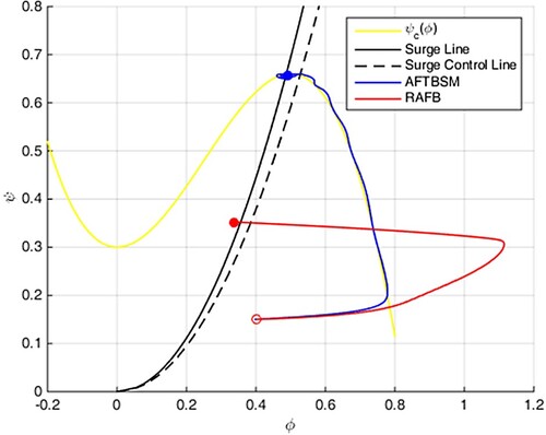
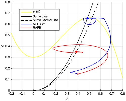
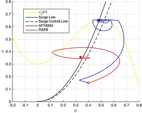
is obtained after a few seconds, which is the desirable operating state for the compressor, while the stall diagram obtained from method [Citation42] shows the occurrence of destructive stall phenomenon after t = 200s. The control signals obtained from the two methods are shown in Figure . Despite of the sharp changes in the control signal obtained from the proposed method, it is clear that the operational limit of the CCV actuator (it must be between zero and one) is observed, while the control signal obtained from method [Citation42] adopts negative values which indicates the operational limit of the CCV actuator is not observed in the control signal, which is naturally non-operational and infeasible. The operating point of the compressor under the proposed controller and method [Citation42] is shown in Figure . As it is known, according to the compressor characteristic curve, the operating point obtained from the proposed method is near the surge line with the highest compression (optimal operating point) and of course the operating state is without surge and without stall while the result obtained from adaptive fuzzy backstepping method [Citation42] has lower compression and efficiency and gradually enters the stall and surge modes.
Figure 3. The compressor pressure in scenario 1.
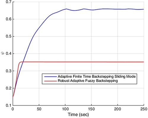
Figure 4. The compressor flow in scenario 1.
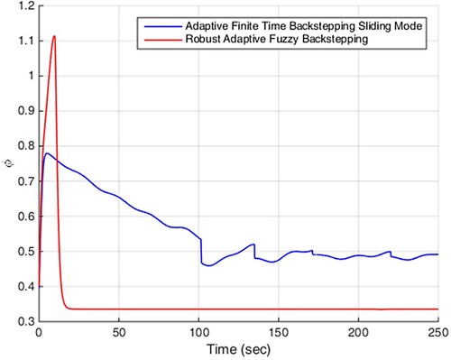
Figure 5. The compressor stall diagram in scenario 1.
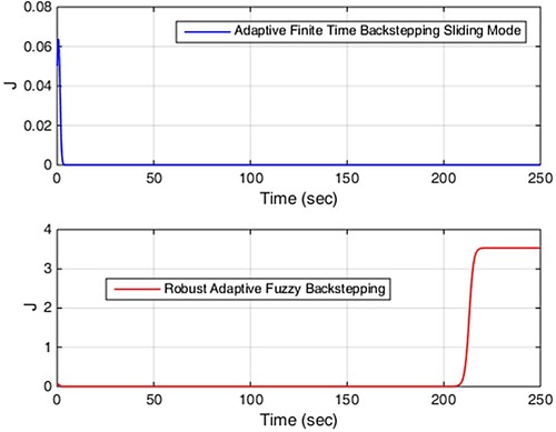
Figure 6. The control signals in scenario 1.
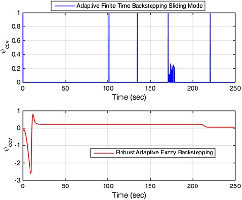
Figure 7. Compression system trajectories in scenario 1.
Scenario 2: Occurrence of stall instability without disturbance
In this scenario, in the case of stall occurrence without disturbance, the proposed controller behaviour is compared with the adaptive fuzzy backstepping method [Citation42].
(37)
(37) For this case, the Gritzer parameter is considered
and the results are shown in Figures . Compressor pressure and flow are shown in Figures and . As can be seen from these figures, the proposed method gives a higher pressure and flow than method [Citation42], and of course the flow obtained under the adaptive fuzzy backstepping controller initially experiences more severe fluctuations. As in the previous scenario, steady-state compression
and
are obtained from the proposed and the adaptive fuzzy backstepping methods, respectively. The most important result obtained in this scenario is given in Figure . As it is known, the application of the proposed control method leads to the removal of the stall after a few seconds, while the adaptive fuzzy backstepping method is not able to remove the stall mode, and this undesirable condition which reduces the efficiency of the compressor and is the beginning of surge, will exist in the compressor system. The control signals obtained in Figure indicate the fact that the operating limits of CCV actuator are fully observed by the proposed method, while the control signals obtained from adaptive fuzzy backstepping method are non-operational and impractical. Figure also shows the compressor operating path, which clearly confirms the better operation of the system (in terms of flow, pressure, stall and surge) under the proposed control method.
Figure 8. The compressor pressure in scenario 2.

Figure 9. The compressor flow in scenario 2.
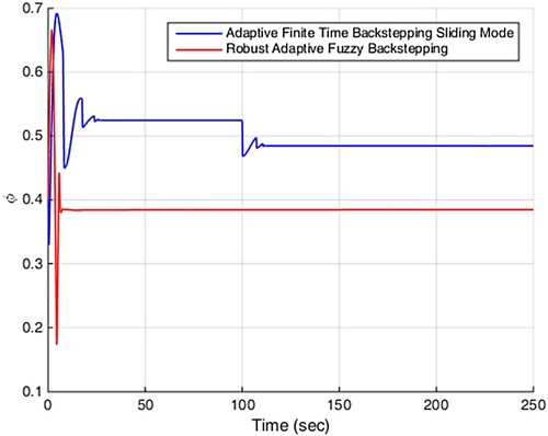
Figure 10. The compressor stall diagram in scenario 2.
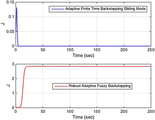
Figure 11. The control signals in scenario 2.
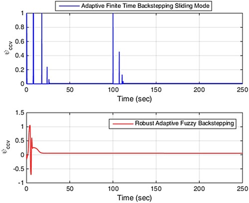
Figure 12. Compression system trajectories in scenario 2.
Scenario 3: Occurrence of stall instability in the presence of disturbance
This scenario is exactly the same as the second scenario, except that disturbance in the form of (38) also enters the compressor system.
(38)
(38) Figures and show that the proposed method is able to better compress and eliminate the effects of disturbance on the pressure and flow of the compressor system, despite the initial slight fluctuations. As shown in Figure , under the adaptive fuzzy backstepping method, the stall has a higher amplitude than the previous scenario, while the method proposed in this paper is well able to eliminate the stall mode. The control signal and the trajectory of the compressor path shown in Figures and confirm the facts obtained in the previous scenarios. The proposed method ensures higher performance close to the surge line with an operational control signal without the occurrence of surge and stall instabilities, while the results obtained from the [Citation42] provide lower performance, impractical control signal and incidence of stall and surge instabilities.
Figure 13. The compressor pressure in scenario 3.
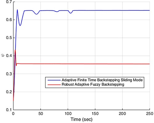
Figure 14. The compressor flow in scenario 3.
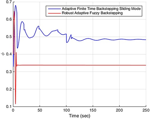
Figure 15. The compressor stall diagram in scenario 3.
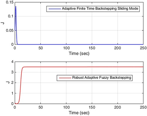
Figure 16. The control signals in scenario 3.
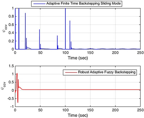
Figure 17. Compression system trajectories in scenario 3.
5. Conclusion
Surge and stall are the two main instabilities limiting compressor performance, and this paper presents a new finite-time method for overcoming these instabilities in the presence of flow-pressure disturbances in addition to uncertainty in the compressor characteristic curve and of course uncertainty in the throttle valve. In this study, the upper bound of disturbance is considered as unknown and the proposed method covers both surge and stall instabilities by combining sliding mode, adaptive and backstepping approaches. In the proposed control method, the design process of the backstepping method was used to obtain the state feedback law, the sliding mode technique was used to ensure robustness against disturbance and uncertainty, and of course the estimation of their upper bounds obtained by the adaptive scheme. The results obtained from MATLAB simulation guarantee the capability of the proposed method in ensuring finite-time active control of surge instability, elimination of stall mode with high-efficiency operation through more compression closer to the surge line, along with elimination of disturbance and uncertainty effects. Future studies can be pursued by considering the effects of noise and the effects of the pipe.
Acknowledgments
This work was financially supported by the Qing Lan Project (SJSH 2022-29), the Key disciplines of the 14th five year plan in Jiangsu Province: Mechanical Engineering (SJYH 2022-2), the First-class specialty in Jiangsu Province: Mechanical Design , Manufacturing and Automation (2020-9), the Project of Laser Processing and Metal Additive Manufacturing Technology and Application (SJK2023-3), and the Young and middle-aged scientific research backbone of NIT (Grant Nos. ZQNGG102, ZQNGG103).
Disclosure statement
No potential conflict of interest was reported by the author(s).
References
- Khoshkalam N, Mojaddam M, Pullen KR. Characterization of the performance of a turbocharger centrifugal compressor by component loss contributions. Energies. 2019;12(14):2711. doi:10.3390/en12142711
- Jiang W, Khan J, Dougal RA. Dynamic centrifugal compressor model for system simulation. J Power Sources. 2006;158(2):1333–1343. doi:10.1016/j.jpowsour.2005.10.093
- Javed A, Pecnik R, Van Buijtenen JP. Optimization of a centrifugal compressor impeller for robustness to manufacturing uncertainties. J Eng Gas Turbines Power. 2016;138(11). doi:10.1115/1.4033185
- Jang SM, Cho HW, Choi SK. Design and analysis of a high-speed brushless DC motor for centrifugal compressor. IEEE Trans Magn. 2007;43(6):2573–2575. doi:10.1109/TMAG.2007.892328
- Mojaddam M, Pullen KR. Optimization of a centrifugal compressor using the design of experiment technique. Appl Sci. 2019;9(2):291. doi:10.3390/app9020291
- Xinqian Z, Anxiong L. Experimental investigation of surge and stall in a high-speed centrifugal compressor. J Propul Power. 2015;31(3):815–825. doi:10.2514/1.B35448
- Willems F. Modeling and control of compressor flow instabilities. IEEE Contr Syst Magaz. Oct 1999;19:8–18.
- Epstein AH, Williams JEF, Greitzer EM. Active suppression of aerodynamic instabilities in turbomachines. J Propuls Power. 1989;5(2):204–211. doi:10.2514/3.23137
- Bøhagen B, Gravdahl JT. Active surge control of compression system using drive torque. Automatica (Oxf). 2008;44(4):1135–1140. doi:10.1016/j.automatica.2007.11.002
- Torrisi G, Grammatico S, Cortinovis A, et al. Model predictive approaches for active surge control in centrifugal compressors. IEEE Trans Control Syst Technol. 2017;25(6):1947–1960. doi:10.1109/TCST.2016.2636027
- Yoon SY, Lin Z, Allaire PE. Control of surge in centrifugal compressors by active magnetic bearings: theory and implementation. London, Heidelberg, New York, Dordrecht: Springer Science & Business Media; 2012.
- Bohagen B, Gravdahl JT. (2002, December). On active surge control of compressors using a mass flow observer. Proceedings of the 41st IEEE Conference on Decision and Control, 2002,Vol. 4, p. 3684–3689). IEEE.
- Uddin N, Gravdahl JT. (2011, January). Active compressor surge control using piston actuation. Dynamic Systems and Control Conference, Vol. 54754, p. 69–76.
- Dominic S, Löhr Y, Schwung A, et al. PLC-based real-time realization of flatness-based feedforward control for industrial compression systems. IEEE Trans Ind Electron. 2016;64(2):1323–1331. doi:10.1109/TIE.2016.2612160
- Osmic S, Berner MO, Schwung A, et al. (2014, October). Flatness-based feedforward control for fast operating point transitions of compressor systems. 2014 IEEE Conference on Control Applications (CCA), p. 1753–1758. IEEE.
- Ghanavati M, et al. A novel combined approach for gas compressors surge suppression based on robust adaptive control and backstepping. J Mech Sci Technol. 2018;32(2):823–833. doi:10.1007/s12206-018-0133-1
- Ghanavati M, et al. A novel combined control based on an adaptive generalized backstepping method for a class of nonlinear systems. Cogent Engg. 2018;5(1):1471787. doi:10.1080/23311916.2018.1471787
- Taleb Ziabari M, et al. Robust adaptive control of surge instability in constant speed centrifugal compressors using tube-MPC. Cogent Eng. 2017;4(1):1339335. doi:10.1080/23311916.2017.1339335
- Chen JP, Webster RS, Hathaway MD, et al. High performance computing of compressor rotating stall and stall control. Integr Comput Aided Eng. 2009;16(1):75–89. doi:10.3233/ICA-2009-0305
- Munari E, D’Elia G, Morini M, et al. Experimental investigation of vibrational and acoustic phenomena for detecting the stall and surge of a multistage compressor. J Eng Gas Turbines Power. 2018;140:9.
- Strazisar AJ, Bright MM, Thorp S, et al. Compressor stall control through endwall recirculation. Turbo Expo: Power Land Sea Air. 2004, January;41707:655–667.
- Tan CS, Day I, Morris S, et al. Spike-type compressor stall inception, detection, and control. Annu Rev Fluid Mech. 2010;42:275–300. doi:10.1146/annurev-fluid-121108-145603
- Margalida G, Joseph P, Roussette O, et al. Active flow control in an axial compressor for stability improvement: on the effect of flow control on stall inception. Exp Fluids. 2021;62(1):1–13. doi:10.1007/s00348-020-03104-4
- Day IJ. Stall, surge, and 75 years of research. J Turbomach. 2016;138(1):p.011001.
- Li X, Chen MZQ, Su H. Finite-time consensus of second-order multi-agent systems via a structural approach. J Franklin Inst. Oct. 2016;353:3876–3896. doi:10.1016/j.jfranklin.2016.07.010
- Wang J, Huang Y, Wang T, et al. Fuzzy finite-time stable compensation control for a building structural vibration system with actuator failures. Appl Soft Comput. 2020;93:106372. doi:10.1016/j.asoc.2020.106372
- Huang Y, Wang J, Wang F, et al. Event-triggered adaptive finite-time tracking control for full state constraints nonlinear systems with parameter uncertainties and given transient performance. ISA Trans. 2021;108:131–143. doi:10.1016/j.isatra.2020.08.022
- Mou J, Duan P, Gao L, et al. An effective hybrid collaborative algorithm for energy-efficient distributed permutation flow-shop inverse scheduling. Future Gener Comput Syst. 2022;128:521–537. doi:10.1016/j.future.2021.10.003
- Li B, Guan T, Dai L, et al. Distributionally Robust Predictive Control Model with Output Feedback. IEEE Transactions on Automatic Control. 2023. doi:10.1109/TAC.2023.3321375
- Fu Z., Hu, M, Guo, Q, et al. Research on anti-rollover warning control of heavy dump truck lifting based on sliding mode-robust control. Proceedings of the Institution of Mechanical Engineers, Part D: Journal of Automobile Engineering. 2023. doi:10.1177/09544070231160901
- Li B, Guan T, Guan X, et al. Optimal Fixed-Time Sliding Mode Control for Spacecraft Constrained Reorientation. IEEE Transactions on Automatic Control. 2023. doi:10.1109/TAC.2023.3341975
- Tan J, Zhang K, Li B, et al. Event-Triggered Sliding Mode Control for Spacecraft Reorientation With Multiple Attitude Constraints. IEEE Transactions on Aerospace and Electronic Systems. 2023;59(5): 6031–6043. doi:10.1109/TAES.2023.3270391
- Lu Y, Tan C, Ge W, et al. Adaptive disturbance observer-based improved super-twisting sliding mode control for electromagnetic direct-drive pump. Smart Materials and Structures. 2023;32(1): 17001. doi:10.1088/1361-665X/aca84e
- Chen B, Hu J, Zhao Y, et al. (2022). Finite-time observer based tracking control of uncertain heterogeneous underwater vehicles using adaptive sliding mode approach. Neurocomputing 481:322–332. doi:10.1016/j.neucom.2022.01.038
- Gravdahl JT, Egeland O. Compressor surge and rotating stall: modeling and control. London: Springer Science & Business Media; 2012.
- Longley JP. A review of nonsteady flow models for compressor stability; 1994.
- Badmus OO, Nett CN, Schork FJ. An integrated, full-range surge control/rotating stall avoidance compressor control system. In 1991 American Control Conference, 1991, p. 3173–3180. IEEE.
- Moore FK, Greitzer EM. A theory of post-stall transients in axial compression systems: Part I—Development of equations; 1986.
- Greitzer EM, Moore FK. A theory of post-stall transients in axial compression systems: Part II—application; 1986.
- Imani H, et al. Constrained nonlinear model predictive control for centrifugal compressor system surge including piping acoustic using closed coupled valve. Syst Sci Control Eng. 2017;5(1):342–349. doi:10.1080/21642583.2017.1367732
- Bhat SP, Bernstein DS. Continuous finite-time stabilization of the translational and rotational double integrators. IEEE Trans Autom Control. 1998;43(5):678–682. doi:10.1109/9.668834
- Sheng H, Huang W, Zhang T, et al. Robust adaptive fuzzy control of compressor surge using backstepping. Arab J Sci Eng. 2014;39:9301–9308. doi:10.1007/s13369-014-1448-1