
 ?Mathematical formulae have been encoded as MathML and are displayed in this HTML version using MathJax in order to improve their display. Uncheck the box to turn MathJax off. This feature requires Javascript. Click on a formula to zoom.
ABSTRACT
Overdeepenings are erosional landforms, cut by glaciers into bedrock in basins and valleys. Overdeepening is the glaciological and geomorphological process that produces these landforms. The overdeepening process is important because it has the potential to influence the response of ice masses to climatic changes. In this paper, we analyze topographic and bathymetric digital elevation models to examine several hundred glacial overdeepenings in Labrador, Canada. We investigate controls upon the location and depth of overdeepenings. Our analyses show that the location of overdeepenings correlate strongly with confluences of glacial valleys and, importantly, that the correlation is strongest where confluence geometry requires the speed-up of ice-flow due to change in valley cross-sectional area. Further, we find that the magnitude of ice-flow speed-up correlates with depth of overdeepenings only for confluences situated in or near major geological fault-zones. Our findings therefore support the hypothesis that overdeepening can be initiated by an increase in ice velocity. Further, we conclude that overdeepening is most efficacious where fractured bedrock enables efficient quarrying. In summary, we find that the primary control upon the location of overdeepenings arises from confluences of glacial valleys due to ice speeding up at these locations, and that the depth of overdeepenings are controlled by rock mass strength. These findings are relevant for landscape evolution modelling and may be used in model testing.
1. Introduction
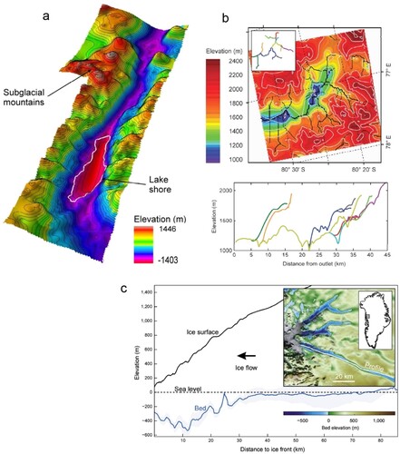
Overdeepenings are glacial landforms that are created by erosion of the bedrock underlying a glacier or ice sheet, to form a closed-basin (Gannett Citation1898; Penck Citation1900). The slightly strange term of ‘overdeepening’ derives from the presumption that glaciers erode below (i.e. over-deepen) typical pre-existing fluvially-valley graded profiles (Gilbert Citation1877; Mackin Citation1948; Sugden and John Citation1976; Lloyd Citation2015). Overdeepenings are common features of glacierized and glaciated landscapes (a). Typically, overdeepenings occur on a scale of hundreds of m2 to many km2 in the horizontal plane, and on a scale of tens to hundreds of metres in the vertical plane (b, c) (Hooke Citation1991; Seaman Citation1998; Kessler et al. Citation2008; Bo et al. Citation2009; Ross et al. Citation2011; Cook and Swift Citation2012; Makos et al. Citation2013), although little work has been undertaken to quantify these metrics (Haeberli et al. Citation2016; Patton et al. Citation2016; Magrani et al. Citation2020).
Figure 1. Examples of overdeepening types and scales. (a) Contoured map of the overdeepened glaciated trunk valley occupied by Ellsworth subglacial lake (100 m contours), West Antarctica (from Ross et al. Citation2011; modified by Cook and Swift Citation2012). (b) (top) Digital elevation model (DEM) of bed topography in the Gamburtsev Mountains, East Antarctica, showing a major overdeepened trough within a pre-glacial fluvial valley network. (inset and bottom) Valley profiles show the depth and extent of overdeepening (inc. smaller cirque, and hanging-valley types) along major valley axes (from Bo et al. Citation2009; modified by Cook and Swift Citation2012). (c) Longitudinal profile of a terminus overdeepening situated beneath Upernavik Isstrøm South outlet glacier in NW Greenland (from Morlighem et al. Citation2014; modified by Patton et al. Citation2016), extending ∼30 km up-valley beneath the ice. The location of the profile is shown in the inset (elevation axis exaggerated).
Overdeepening is of interest because it is an important glaciological and geomorphological process that is thought to be a major control upon glacial landscape development, and which has the potential to influence the response of ice masses to changes in climate by controls and feedbacks on ice velocity and ice surface elevation (Egholm et al. Citation2011, Citation2012). The study of the location and size of overdeepenings may enable us to make inferences on processes and landforms that will aid development of a broader understanding of the relationships and feedbacks within glacial systems, and of landscape evolution (Cook and Swift Citation2012). Overdeepenings are also of interest in an applied sense, such as in geotechnical engineering studies (Taylor and Wilson Citation1997), or in geohazard assessment analyses (Frey et al. Citation2010; Fischer et al. Citation2021). Some studies, for example, have investigated the use of overdeepenings as aquifers (Cormier et al. Citation1998; Schneider and Rybach Citation1999), for hydropower generation (Malyutkin and Molokov Citation1985; Linsbauer et al. Citation2012), or as potential locations for storage/disposal of nuclear waste (Talbot Citation1999; Sykes et al. Citation2009).
Overdeepenings are typically found within glacial troughs and cirques (Linton Citation1963; Sugden and John Citation1976) and are often inferred to have been produced at the confluence of two glaciers within a valley network (MacGregor et al. Citation2000). At locations of confluence, such as where a tributary joins a main trunk valley, ice velocity should locally increase due to the larger mass of ice now draining through the smaller cross-sectional area of the main trough. This local increase in velocity might then increase glacial erosion to produce an overdeepening (Holtedahl Citation1967; Glasser Citation1995; MacGregor et al. Citation2000; Herman and Braun Citation2008; Kessler et al. Citation2008; Patton et al. Citation2016). Overdeepenings are thought to develop by glacial erosive processes, primarily by quarrying but also by abrasion and by glacial meltwater erosion; usually governed by an ice erosion feedback (Hooke Citation1991; Alley et al. Citation2003).
The pre-existing valley geometry (topography) and geology are also thought to be significant controls upon the location and development of overdeepenings (Glasser Citation1995; MacGregor et al. Citation2000; Preusser et al. Citation2010; Pomper et al. Citation2017; Gegg et al. Citation2021), focusing glacial erosive processes and exploiting zones of less competent and/or faulted bedrock (Haynes Citation1968; MacGregor et al. Citation2000; Seguinot Citation2008; Burschil et al. Citation2019). Glacial erosion will be more effective within structural fault zones where exposed bedrock is blockier due to jointing and shearing which yields many lines of weakness that can be exploited by glacial quarrying (Hooke Citation1991; Hallet Citation1996; Dühnforth et al. Citation2010; Hooyer et al. Citation2012). Within such weaker zones, the quarrying process will provide a greater quantity of entrained debris within the glacier sole, creating a positive feedback which will contribute further towards bedrock erosion by providing the tools necessary for increased abrasion (Boulton Citation1996).
We assess the extent to which a preferential co-location exists between overdeepenings and glacial confluences, exploring these topographical controls on overdeepening location. We test the hypothesis that overdeepening existence here is a result of ice speed-up at tributary confluences, using measurements of valley cross-sectional area. We then examine the influence of bedrock mass strength upon overdeepening depth – a geological control – testing the hypothesis that depth is greater in confluences with weaker bedrock because of the greater potential for erosion.
2. Materials and methods
In this empirical investigation, we use GIS tools and digital elevation models (DEMs) and datasets to systematically study several hundred glacial overdeepenings in the Labrador province of Canada (). We use the geographical information system (GIS) software ESRI ArcGIS Desktop for geospatial analysis, with use of the Spatial Analyst and 3D Analyst extensions, and perform plotting and linear regression in Microsoft Excel with use of the Data Analysis Toolpak. DEMs and other datasets are selected for suitability in the task of overdeepening identification. DEMs and datasets are available at no cost.
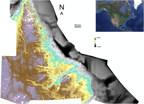
Figure 2. The study region in Labrador, Canada and surrounding region. Land topography data (lower left coordinate 52.0, −67.8 DD) (from SRTM3) ranges from sea level (turquoise) to ∼1600 m a.s.l (white). Bathymetric data (from GEBCO) of the adjacent continental shelf is shown in greyscale, ranging from sea level (white/grey) to ∼ 1700m depth (black). The inset image (top right) shows the location of the study region (white box).
2.1 Study region
The Labrador region of Canada (and north-eastern Quebec) and adjacent continental shelf have been selected for study because the region has an extensive history of glaciation during the Quaternary. Much of Labrador has evidence for at least two phases of ice movement within the Quaternary. These are probably related to shifting Late Wisconsinan dispersal centres (Batterson Citation1990). During the Late Wisconsin (the last glacial period), the Laurentide Ice Sheet reached maximum extent (in the study region) 15.5 cal. ka BP (Occhietti et al. Citation2011), when it advanced to occupy the continental shelf region offshore of the east coast of Labrador, in the Labrador Sea. Towards the Labradorian east coast, ice movement was topographically controlled during the late glacial stages (Batterson Citation1990). There is strong evidence for east flowing valley glaciers post-dating northeast-flowing ice on surrounding highlands (Batterson Citation1990; Winsborrow et al. Citation2004; Batterson and Liverman Citation2011).
The region has varied geology and much structural faulting () owing to its location and antiquity. Bedrock within the study region is part of the ancient Canadian Shield (Laurentian Craton). The Torngat mountain range (the main orogenic belt within the region) was formed during the Torngat Orogeny over 1.7 Ga ago (St-Onge et al. Citation2009) and has since been extensively denudated, including by numerous (ice sheet scale) glaciations (Staiger et al. Citation2005; Occhietti et al. Citation2011). The region has complex (mostly igneous and metamorphic) geology, with significant structural faulting (Wardle et al. Citation1997; Davenport et al. Citation1999) due to the extensive and complicated geological history of the region (St-Onge et al. Citation2009). In the northern part, structural faulting is largely east–west, and north-west to south-east trending within the Torngat orogenic belt (the northern mountains), and proximal to the North Atlantic (Nain) Craton (to the east) and the South-eastern Churchill Province (to the west) (Wardle et al. Citation1997). Here, structural faulting is mainly the result of continental collision and crustal amalgamation between a north-eastern composite continent (consisting of the North American Craton and Torngat orogenic belt) and the south-western (North American) Superior Craton (2.3–1.8 Ga ago) (St-Onge et al. Citation2009), sutured by a southwards projecting promontory of the Archaean Rae Province (i.e. the South-eastern Churchill Province) (Wardle and Van Kranendonk Citation1996). In the southern part of the study region, structural faulting is largely north-west to south-east, with some south-west to north-east trending (Wardle et al. Citation1997) within the (younger) Grenville Province. Here, structural faulting is mainly the result of over 800 Ma of diverse tectonic activity at the margin of pre-Labradorian Laurentia (i.e. cratonic compression and amalgamation, basin extension, arc accretion, and plutonism) before crustal stability was achieved (1.3-1.0 Ga ago) (Gower Citation1996).
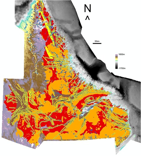
Figure 3. The main geological zones for the study area (modified from Wardle et al. Citation1997); igneous (orange), metamorphic (red), sedimentary (brown), and major faults (black) with associated shear and minor fault zones (yellow) collectively termed structural zones. The geological zones indicate the extent of geological analysis. Glacial confluence perimeters are shown in blue (see text). Background elevation model is the same as .
Part of the Swiss Alps is also investigated to test the replicability of outcomes found in Labrador. The test area spans from Lake Geneva in the west to Scima da Saoseo in the east, and from Mont Blanc in the south to Pizol in the north. The region has a similar history of extensive glaciation during the Quaternary (Champagnac et al. Citation2007; Buoncristiani and Campy Citation2011) and a broadly similar (orogenic) but much younger (last 100 Ma) geology to that of Labrador, with much structural faulting (Froitzheim et al. Citation1996; Swiss Federal Office of Topography (SwissTopo) Citation2010). For further explanation, see Lloyd (Citation2015).
2.2 Datasets
The datasets utilized are:
US NASA Shuttle Radar Topography Mission ‘Finished’ (void filled) research grade (version 2) 3 arc-second land topography data (SRTM3), with 1 m vertical resolution (US NASA Citation2005a).
The corresponding water body dataset for SRTM3 (US NASA Citation2005b).
General Bathymetric Chart of the Oceans (GEBCO) bathymetry data (version 20091120) (GEBCO Citation2009a) at 30 arc-second grid spacing, with 1 m vertical resolution. A database of over 290 million shallow ship-track soundings (from many sources), with interpolation between soundings guided by satellite-derived gravity data (Smith and Sandwell Citation1997; GEBCO Citation2009b). The gravity data are based on the Smith and Sandwell global topographical grid (version 11.1, September 2008). Predicted depths are based on version v16.1 of the Smith and Sandwell gravity anomaly from GeoSat and ERS-1 satellite altimetry, created March 2007 (Sandwell and Smith Citation1997; GEBCO Citation2009b).
Geological map of Labrador, 1:1,000,000 scale, polygon dataset (Wardle et al. Citation1997), based on a database produced by the Department of Mines and Energy, Geological Survey, Government of Newfoundland and Labrador, Canada (Davenport et al. Citation1999).
Geological map of Switzerland and adjoining parts of neighbouring countries (Swiss Federal Office of Topography (SwissTopo) Citation2010), 1:500,000 scale, polygon dataset (version 1.2).
2.2.1 Dataset accuracy
The accuracy of the SRTM data is discussed in Rabus et al. (Citation2003). More detailed analysis is found in Rodríguez et al. (Citation2005). There is less than or equal to 12.6 m absolute horizontal circular error for 90% of the data, and relative vertical linear error is < = 9.8 m, globally (Rodríguez et al. Citation2005). For Labrador, an absolute vertical linear error is < = 5 m for >90% of the data (Rodríguez et al. Citation2005).
Less than 25% of global bathymetry has been mapped (The Nippon Foundation-GEBCO Seabed Citation2030 Project Citation2022). Hence, gridded mapping of bathymetry is heavily interpolated and highly variable in quality. GEBCO global bathymetry data nevertheless have a standard grid spacing of 900 m resolution and use contour intervals of 500 m depth, with 200 and 100 m contours in shallow zones only where justified (GEBCO Citation2003). Attempting to assess GEBCO grid quality is difficult, owing to the composite nature of the dataset and the inconsistency in methods used to produce it. As a guide, multibeam swath sonar and hydrographic surveys undertaken prior to 1998 will have a vertical accuracy of 0.3 m for depths of less than 30 m, and a vertical accuracy of 1% of depth for depths of greater than 30 m (GEBCO et al. Citation2014). Coastal areas in and around the fjords and bays of Labrador are likely to have some of the better bathymetry data, owing to comparatively dense survey coverage relative to many open water locations, and because fjordal areas are typically well constrained by surrounding land topography.
The geological mapping polygon datasets are compiled from published and unpublished sources. The published map scales reflect the limitations in scale/resolution, accuracy and coverage of the relevant source documents/datasets, for which specific accuracy information is not available. The datasets adhere to good map accuracy standards. Further discussion of DEM and dataset accuracy can be found in Lloyd (Citation2015).
2.3 Approach and rationale
The full methods utilized in this work, data thresholding and quality control procedures, and some sensitivity testing of landform definition parameter choices, are discussed in Lloyd (Citation2015). For brevity, a synopsis of methods is elucidated here.
The GIS ‘Fill’ and ‘Minus’ tools are utilized within ESRI ArcGIS to fill closed contour topographic lows in DEMs and so identify as many potential overdeepenings as possible. DEMs and datasets are projected (to UTM 20N for Labrador, UTM 32N in the Swiss test case) for analysis. Area and depth values of topographic lows are calculated in ArcGIS, and thresholding undertaken via the generation of histograms in Excel in order to identify false positives for removal. The optimum area threshold is identified by the area value for which there is the most significant decrease in the number of topographic lows of 1 m depth. Lows with 1 m depth are assumed to be artifacts/errors because of the vertical accuracy specification of the datasets. From analyses, we identified a depth threshold of 5 m as a reasonable minimum depth at which a potential overdeepening might typically begin to be visually identifiable in the field, and an optimal area threshold of 0.0357 km2 (SRTM3) and 2.3546 km2 (GEBCO). This means that we identify only larger potential overdeepenings on the seafloor (compared to on land) due to the limited spatial resolution of the bathymetry data.
Potential water-filled overdeepenings may be absent or obscured in topographic data. For this reason, lakes are identified from the inland water bodies dataset and merged with the thresholded topographic lows so as to maintain contiguous area. For these lows, depth values will be erroneous (i.e. created by radar backscatter from water surface during mapping) and so are removed. Visual assessment of the output allows further filtering if the topographic low has been formed by some other physical process or anthropogenic activity.
Overdeepenings in low lying valleys typically accumulate localized superficial glacio-fluvial deposits or are colonized by vegetation. Again, this may mean that overdeepenings are absent or obscured in topographic data. Here, we apply a low pass 3 × 3 filter (once) to topographic lows, using the ‘Filter’ tool in ArcGIS, so as to improve area contiguousness. For Labrador it was straightforward to define low lying valleys due to the natural break in topography into the fjordal network at 345 m a.s.l. We retain original overdeepening depth values (as points) and polygonize overdeepenings for analysis.
Glacial valley confluences are identified and delineated manually (i.e. polygonized) via visual inspection of projected DEM elevation, slope, and contour data. As detailed in Lloyd (Citation2015), a combined GIS and visual procedure has been adopted to ensure consistency across measurements of unit area and valley cross-sectional area (CSA) within each confluence. For valleys, now deglaciated, it is difficult to be precise about area calculations because of the difficulty in working out how far up the valleys sides to include within each confluence. Hence, the adopted method is based on choosing the optimum contour (20 m elevation spacing) that summarizes each confluence including its main trunk and tributaries. The contour selected is that which traverses most of the valley sides within the confluence system encompassing the highest slope angles as computed from the DEM. A horizontal glacier top surface is assumed by the use of this method. At the optimum contour, the down-tributary end of a confluence tributary valley is identified by divergence of the tributary valley-sides by > = 45o where it is visually apparent that the tributary joins the main trunk valley. This is a standardized position where tributary valley width and tributary valley CSA are measured. The up-tributary end of a confluence is positioned one tributary valley width up-tributary (measured along each valley-side) from this location. Similarly, the down-trunk end of a confluence is located where minimum valley width is encountered downstream of where tributaries join the main trunk valley. The down-trunk end of a confluence is a standardized position where trunk valley CSA is measured.
The process of confluence identification and delineation obeys a further set of certainty criteria to ensure consistency in confluence definition. For further details, see Lloyd (Citation2015). At the selected contour value:
Ice flow direction should appear realistic between tributary and trunk valleys in the confluence – having a clear ‘birds foot’ appearance with y-shaped junctions.
Ice flow direction should be definable through the valley network immediately surrounding the confluence.
Ice flow capacity of tributaries should be similar (i.e. tributaries should be of similar size) in the confluence, and tributary valleys should be independent of one another and not hanging.
2.3.1 Overdeepening incidence within confluences
An assessment is made of the strength of the co-location relationship between overdeepenings and confluence (per unit area) within the Labrador study region. ‘Actual’ co-location is measured using ArcGIS and the ‘Intersect’ tool. The total area of overdeepenings (AOD), confluence(AConf), and the study region (ARegion) are also measured. The actual co-location is compared with the strength of expected co-location (ECo-loc) that would arise randomly calculated as follows:
The chi-squared test of independence for the relationship is undertaken using the ‘CHISQ.TEST’ function in Excel.
2.3.2 Ice velocity as a control upon overdeepening incidence with confluences
A major topographical control upon overdeepening location and size is likely via valley cross-sectional area (CSA) change influencing ice velocity and erosion. As with any other flowing media, where ice encounters a local decrease in valley CSA along its course (e.g. a constriction) there must be a localized flow acceleration for continuity reasons, and a corresponding increase in erosion (a). It can therefore be reasoned that potential glacial erosion should increase with valley CSA reductions (b) in these settings.
Figure 4. Schematic plans of topographically-induced overdeepenings. (a) A constriction in a valley. The narrower part of the valley with smaller cross-sectional area (CSA) will experience faster ice flow, and hence more erosion, than the wider part, thus producing an overdeepening here. (b). Schematic diagram of how valley CSA exerts a control on local ice velocity, potentially with a corresponding increase in erosion. (c) Valley confluences are also expected to be areas of localized ice velocity speed-up and maxima in local glacial erosion. Therefore overdeepenings should occur here (see text).
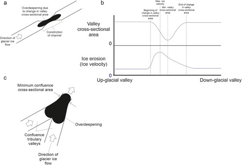
Valley confluences are possibly the most easily identifiable exemplar of valley CSA decrease within landscapes (c). It can be reasoned that glacial erosion within valley confluences will work over time to balance the sum of tributary valley CSAs with trunk valley CSA, meaning that confluence allometry may naturally reach an equilibrium steady-state in which ice speed-up will no longer occur. However, from visual analysis of landscapes using DEMs, we suggest that valley confluences seldom reach this state over glacial timescales, most probably because the process is self-limiting (i.e. slowing, with insufficient time available in the glaciations in which to complete). As a result, an effective decrease in CSA is typically observed through glacial valley confluences as tributaries merge into the trunk (see later).
This first-order control of downstream changes in CSA upon ice velocity and potential erosion across confluences may be complicated by a second-order control. It can be reasoned that ice flow will become less affected by bed and lateral drag (i.e. frictional forces), where tributaries merge into a trunk valley, because ice will have proportionally less contact area with the valley floor and sides. This should increase ice velocity at this location (b). What this means for glacial erosion is less clear.
If glacial valley CSA change is a primary control upon overdeepening locations, then we expect that overdeepenings will be preferentially identified in association with confluences. Such overdeepenings may be of a magnitude that scales with the proportional change in CSA across the confluence.
We suggest that maximum ice velocity should occur up-glacier of the location of minimum CSA within the valley constriction (b). This is for (second-order control) flow continuity reasons, as supported by empirical observations (Gudmundsson et al. Citation1997; Yu et al. Citation2010; Millan et al. Citation2019).
Based on the discussion so far we presume that overdeepenings should mostly be positioned spanning the location of minimum CSA and that the maximum depth of overdeepenings should be a short distance upstream from here.
To address the ideas and hypotheses above, we calculate change in CSA through a confluence via measurement of valley CSA profiles at the standardized positions within tributary and trunk valleys. Measurements are undertaken using the ‘Interpolate Line’ tool in ArcGIS. Valley CSA data plots are constructed using Excel, and the CSA of each valley is determined by trapezoid rule calculation. The rule calculates the area under the curve for a valley profile and is repeated on (the straight line of) a notional second profile (drawn from the first to the last data point of the valley profile). The difference between the calculated area values of the two profiles is the CSA of the valley. Change in valley CSA through a confluence is then determined by the calculation of a confluence ‘ratio’:
The ratio is an index of potential ice velocity speed-up through the confluence. Thus ratio values of 1 indicate parity of ice flow within a confluence (i.e. no ice speed-up, and valley CSA maintained through the confluence), with values greater than 1 indicating an increase in ice flow (i.e. ice speed-up, and valley CSA decrease through the confluence). As previously discussed, we expect that subglacial erosion will act to lead the confluence ratio to equal 1 over time, by increasing the cross-sectional area of the trunk valley.
Comparison of the frequency distribution of confluence ratios provides evidence regarding the degree to which valley CSA change through a confluence affects the location of overdeepenings within the study region. If a causal relationship is to be supported then a significantly greater number of confluences co-located with overdeepenings must demonstrate ice speed than confluences that are not co-located.
Up-tributary overdeepenings, found in association with confluence, are excluded from analysis where the overdeepening does not extend downstream into the trunk valley. Such overdeepenings tend to be very small in area. This quality control better isolates the effects of topographical controls (upon overdeepening location and size) that might operate at confluence valley scale. Quality control is discussed further in Lloyd (Citation2015).
2.3.3 Overdeepening and confluence incidence with particular rock types or structure
We modify and repeat the co-location relationship method to assess the co-location of each geological zone (igneous, metamorphic, sedimentary, and structural – ) with overdeepenings, confluence, and confluence co-located with overdeepenings (per unit area). As before, we evaluate the strength of each set of co-location relationships and undertake chi-squared testing.
The geological maps used in this study denote major faults as lines. For our statistical analysis of confluence regions and overdeepenings, we extend the area of structural damage (i.e. shear and minor fault zones) surrounding the faults to three times mean valley width at the down valley end of only those confluences within the bounds of the geological data. Calculations are undertaken on valley CSA data plots using Excel. For Labrador, the calculated value is 5.67 km, and for the Swiss Alps replicability test this value is 2.94 km. This is reasonable given visual assessment of the DEMs and geological data, which indicate that valley networks tend to follow major faults. Topographical (and other) controls are likely to exploit such geological weaknesses (via erosional processes) in order to initiate and develop valleys. Hence, the zone of influence of the major faults can be considered to occur on a similar scale to that of the valleys (Lloyd Citation2015).
2.3.4 Bedrock mass strength as a control upon overdeepening depth within confluences
We evaluate the influence of confluence bedrock mass strength upon the depth of overdeepenings via analysis of ice velocity speed-up correlation with depth of overdeepenings for confluences within each geological zone. If bedrock mass strength is a strong control upon depth of overdeepenings within confluences then it is expected that overdeepenings will be deeper when found in weaker rocks, either due to lithology or structure.
Analysis involves the separate assessment of scatter plots of confluence ratio plotted against the depth of confluence co-located overdeepenings per each geological zone. Scatter plot relationships are assessed via linear regression analysis (least squares method) using the Excel Data Analysis Toolpak. The trend and strength of relationships are assessed, using adjusted r2 value and significance level. We assess the relationship between speed-up in confluences and a metric (i.e. depth) of overdeepenings. Therefore, we exclude from analysis the confluences that demonstrate a decrease in ice velocity (i.e. ratio values < = 1) or no ice velocity speed-up.
For a given geological zone, a causal relationship between bedrock mass strength and depth of overdeepenings will be supported only where a strong co-location relationship is found between the geological zone and each of overdeepenings, confluence, and confluence co-located with overdeepenings. Further, this relationship must be found alongside a statistically significant linear regression relationship between confluence ratio and depth of overdeepenings within confluences for said geological zone. Similarly strong co-location relationships must not be found within the remainder of the study region when all other geological zones are assessed together as one.
Where very large overdeepenings (by area) are found in association with valley confluence, the disparity in scale between the confluence and the overdeepening means that the primary control upon overdeepening location and size cannot be one operating only at valley scale. We exclude such overdeepenings from this analysis, thus better isolating the potential effects of geological controls (upon overdeepening location and size) at confluence scale. Exclusions include very large overdeepenings associated with more than one confluence or geological zone. For the same reason, we also exclude any confluences that fall short of fully meeting certainty criteria at valley scale (see section 2.3). Quality control measures are undertaken in addition to that detailed in section 2.3.2, and are discussed further in Lloyd (Citation2015).
3. Results
We here demonstrate evidence in support of the existence of a type of overdeepening that is the result of ice speed-up within glacial valley confluences. We also present evidence that the depth of overdeepenings is greater in glacial valley confluences that have weaker bedrock, which we suppose is due to the greater potential for erosion and removal of material in such geological settings. Finally, results are presented for a smaller group of confluences and overdeepenings, within an additional test area, to determine whether outcomes of our main analysis are replicable elsewhere.
3.1 Overdeepening incidence with confluence
To assess whether overdeepenings are preferentially located at glacial valley confluences, an assessment is made of the strength of the co-location relationship between overdeepenings and confluence (per unit area). This value is compared with the strength of co-location that would arise randomly. Summary statistics for the dataset are displayed in , and those for the co-location relationship in . The result is most significant when the proportion of the expected value is largely different than 1.0. Actual proportion of overdeepened area co-located with confluence is significantly greater than expected (1.7x). Overdeepened area co-located with confluence constitutes only 2.79% of overdeepened area in the study region. Further co-location statistics are explored in Lloyd (Citation2015). The outcome of the chi-squared test of independence for the relationship between confluence and overdeepenings is shown in , indicating a statistically significant relationship.
Table 1. Summary area statistics for the Labrador study region.
Table 2. Summary statistics showing the area co-location relationship between glacial confluence and overdeepenings.
Table 3. The chi-squared test of independence for the relationship between confluence and overdeepening.
3.2 Ice velocity as a control upon overdeepening incidence with confluences
Comparison of the frequency distribution of confluence ratio for subsets of confluences (co-located and not co-located with overdeepenings) shows the extent to which valley CSA change through a confluence affects overdeepening location within the study region. The frequency distribution is shown in . Summary statistics for confluences with speed-up are shown in . This simple GIS analysis (after quality control detailed in section 2.3.2) shows that 312 (56.2%) out of a total of 555 confluences found in the study region are co-located with overdeepenings, and that 235 (75.3%) of these demonstrate ice velocity speed-up (i.e. a ratio > 1). The mean ratio value is much higher for co-located confluences. Findings demonstrate that co-located confluences show significantly greater ice velocity speed-up (due to change in valley CSA) than do confluences that do not contain overdeepenings. This indicates that ice velocity influences the location of overdeepenings in confluences, and so the likelihood of an overdeepening occurring.
Figure 5. The frequency distribution of ice-flow speed-up ratio, for confluences co-located (blue, top) and not co-located (light blue, bottom) with overdeepenings. (Top) 75.3% of co-located confluences display a speed-up ratio greater than 1, with long positive skew. (Bottom) Only 56.4% of confluences that are not co-located display a speed-up ratio greater than 1, with significantly shorter positive skew. Co-located confluences show significantly greater ice velocity speed-up (due to change in valley CSA) than do confluences that do not contain overdeepenings. This finding demonstrates that ice velocity influences the location of overdeepenings in confluences, and so the likelihood of an overdeepening occurring.
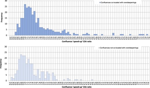
Table 4. Summary statistics showing the number, percentage, and average ratio values of confluences demonstrating ice velocity speed-up (i.e. a ratio > 1), for subsets of confluences.
3.3 Overdeepening and confluence incidence with particular rock types or structure
To assess whether overdeepenings are deeper in confluences with weaker bedrock mass strength, an assessment is made of the strength of the co-location relationship between confluence and specific geological types (per unit area). This value is compared with the strength of co-location that would arise randomly. This shows if there is a preference for particular rock type (igneous, metamorphic, sedimentary) or structures (faulting). Summary area statistics associated with the geological dataset are displayed in , and for the co-location relationships are in . The result is most significant when the proportion of the expected value is largely different than 1.0. Only in the structural zone is the actual proportion of confluence area co-located with geological zone significantly greater than expected (2.0x). Confluence area in the structural zone constitutes 50.2% of confluence area in the study region. The outcome of the chi-squared test of independence for the relationship between the structural zone and confluence is shown in , indicating a statistically significant relationship.
Table 5. Summary area statistics used in analysis of the influence of particular rock types or structure.
Table 6. Summary statistics showing the area co-location relationship between geological zones and glacial confluence.
Table 7. The chi-squared test of independence for the relationship between structural (ST) zone and confluence.
Similarly, the strength of the co-location relationship between overdeepenings and specific geological types is compared with that expected by random chance to assess if the latter exerts a control on overdeepening occurrence. Summary statistics are shown in . The result is most significant when the proportion of the expected value is largely different than 1.0. Only in the structural zone is the actual proportion of overdeepened area co-located with geological zone significantly greater than expected (1.6x). Overdeepened area in the structural zone constitutes 38.5% of overdeepened area in the study region. The outcome of the chi-squared test of independence for the relationship between the structural zone and overdeepenings is shown in , indicating a statistically significant relationship.
Table 8. Summary statistics showing the area co-location relationship between geological zones and overdeepenings.
Table 9. The chi-squared test of independence for the relationship between structural zone (ST) and overdeepenings.
For confluences with overdeepenings, the strength of the co-location relationship between confluence and the structural zone is compared with that expected randomly. Summary statistics are shown in . The result is most significant when the proportion of the expected value is largely different than 1.0. For confluences with overdeepenings, the actual proportion of confluence area co-located with the structural geology zone is significantly greater than expected (2.0x). Confluence area (co-located with overdeepenings) in the structural zone constitutes 50% of confluence area in the study region. The outcome of the chi-squared test of independence for this relationship is shown in , indicating a statistically significant relationship.
Table 10. Summary statistics showing the area co-location relationship between glacial confluence and the structural geology zone, for confluences with overdeepenings.
Table 11. The chi-squared test of independence for the relationship between structural zone (ST) and confluence, for only those confluences that contain overdeepenings (OD).
Other simple GIS analysis (after quality control detailed in section 2.3.2) shows that 268 (60.9%) out of a total of 440 confluences found in the geological study region are co-located with overdeepenings. Of these confluences, 121 are located within the structural zone with 90 (74.4%) demonstrating ice velocity speed-up (i.e. a ratio > 1). The mean ratio value is 1.6 for confluences co-located with overdeepenings within the structural zone. General statistics re. confluence metrics are shown in and are explored in the discussion.
Table 12. Statistics, for subsets of confluences within the Labrador study region.
3.4 Bedrock mass strength as a control upon overdeepening depth within confluences
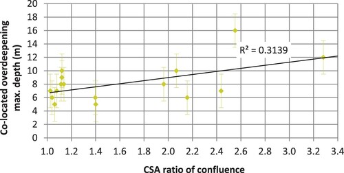
It is fair to presume that due to the high level of faults, joints and other planes of weakness within the defined structural geology zone, that these areas have lower bedrock mass strength and are perhaps more susceptible to glacial erosion. To explore this, analysis considers the relationship between confluence CSA ratio (ice velocity speed-up) and overdeepening depth within and outside the structural zone. Although no relationship is found outside the structural zone, a statistically significant relationship is found to exist in SRTM3 data within the structural geology zone (see ) – after quality control detailed in section 2.3.4 (Lloyd Citation2015). A positive linear relationship is found, with an adjusted r2 value of 0.265 (a moderately strong goodness of model fit when encountered in nature) and a significance value (p-value) of 0.024. Hence, there is confidence that the relationship has not occurred by chance because it is comfortably statistically significant at the 95% confidence level. This scenario indicates that overdeepening depth is greater in confluences influenced by weaker (faulted) bedrock within the study region.
Figure 6. A statistically significant relationship is demonstrated between confluence CSA ratio (ice velocity speed-up) and co-located overdeepening depth in SRTM3 data within the structural geology zone. No such relationship is found elsewhere in Labrador. This scenario indicates that overdeepening depth is greater in confluences influenced by weaker (faulted) bedrock within the study region. Error bars indicate the largest absolute vertical linear error of the SRTM3 data, for which >90% has an absolute vertical linear error of < = 5 m (Farr et al. 2007). The potential error of CSA ratio values is not easily quantified but is not likely to limit interpretation of results.
3.4.1 Testing reproducibility
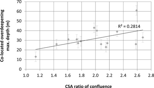
It is useful to examine the extent to which outcomes of the bedrock erosion hypothesis for Labrador are more widely replicable. So we again investigate the relationship between confluence CSA ratio and overdeepening depth within a structural zone. This time we consider a small group of confluences that contain overdeepenings, in the Swiss Alps – a region noted for its overdeepenings. The relationship is found to be statistically significant within SRTM3 data (see ), after quality control detailed in section 2.3.4 (Lloyd Citation2015). Relative to the Labrador study, findings show an improved positive linear relationship, with a slightly weaker adjusted r2 value of 0.230. Nevertheless, this remains a moderately strong model fit in nature. The relationship has a slightly weaker significance value (p-value) of 0.035 when compared to that for Labrador, although still comfortably statistically significant at the 95% confidence level. The relationship supports the outcome of the Labrador analysis, that overdeepening depth is greater in confluences influenced by weaker (faulted) bedrock.
Figure 7. In the Swiss replicability test, a statistically significant relationship is demonstrated between confluence CSA ratio (ice velocity speed-up) and co-located overdeepening depth in SRTM3 data within the structural geology zone. This finding supports the outcome of the Labrador analysis, that overdeepening depth is greater in confluences influenced by weaker (faulted) bedrock. Error bars indicate the largest absolute vertical linear error of the SRTM3 data, for which >90% has an absolute vertical linear error of < = 10 m (Farr et al. 2007). The potential error of CSA ratio values is not easily quantified but is not likely to limit interpretation of results.
4. Discussion
Alongside studies of overdeepenings undertaken for other glaciated regions (Haeberli et al. Citation2016; Patton et al. Citation2016; Magrani et al. Citation2020) our results provide quantification of overdeepening metrics and assessment of some of the controls that determine the location and depth of overdeepenings. The frequency distribution of confluence ratio for subsets of confluences (co-located and not co-located with overdeepenings) shows that valley CSA change through a confluence affects overdeepening location within the Labrador study region. Speed-up (as inferred by the CSA ratio) is found more often in confluences where an overdeepening is present than where an overdeepening does not occur ().
The observed co-location of overdeepenings with confluence is 1.7 times higher than is expected was co-location to occur as a result of random chance. The outcome of the chi-squared test of independence for this relationship is shown in , confirming a statistically significant relationship. The probability (P-value) of the observed chi-square value being a chance occurrence is much smaller than the pre-supposed level of significance (Alpha).
The majority of confluences demonstrate some degree of speed-up (), even when they have no overdeepenings. However, the percentage of confluences that demonstrate speed-up is very much higher for confluences co-located with overdeepenings (75.3%) than for confluences without (56.4%). These findings are supported by mean, mode, and median ice velocity speed-up values, which are notably higher for confluences with overdeepenings than those without (e.g. mean value of 2.3 and 1.3 respectively).
The analysis therefore provides strong evidence in support of the hypothesis that overdeepenings are preferentially located at glacial valley confluences because this is where ice velocity speed-up occurs. As expected, visual analysis confirms that overdeepenings are typically found to span the position of minimum valley CSA in the trunk of the confluences. Further analysis (Lloyd Citation2015) has found no relationship between confluence CSA ratio and overdeepening depth within the study region as a whole. Inferred speed-up through a confluence does not seem to affect the size of co-located overdeepenings.
The observed co-location of igneous, metamorphic, and sedimentary geological zones with glacial confluence are each lower than expected by random chance. Co-location of the structural geology zone with glacial confluence is 2.0 times higher than is expected to occur randomly. This suggests that there is no control regarding igneous, a strong avoidance of confluence with sedimentary and metamorphic rock types, and a strong preference for confluence to be located in the structural zone. The outcome of the chi-squared test of independence for this latter relationship is shown in , confirming a statistically significant relationship.
Similarly, co-location of igneous, metamorphic, and sedimentary geological zones with overdeepenings are each slightly lower than expected, suggesting no relationship. Co-location of the structural geology zone with overdeepenings is 1.6 times higher than expected, suggesting that there is a strong preference for overdeepenings to occur in structural zones. This supports the finding of Magrani et al. (Citation2020), that many overdeepenings occur in weakened bedrock. The outcome of the chi-squared test of independence for the relationship is shown in , confirming a statistically significant relationship.
For confluences that contain overdeepenings, the co-location of glacial confluence with the structural zone is 2.0 times higher than expected were co-location to occur randomly. This, again, suggests a strong relationship between the structural zone and confluence location. Summary statistics are shown in . The outcome of the chi-squared test of independence for this relationship is shown in , confirming a statistically significant relationship.
General analysis indicates that groups of confluences co-located with overdeepenings are consistently larger and wider than confluences in general (). Further, confluences within the structural zone are particularly large (by mean area, 17.3 km2) and wide (in trunk valley, mean width 2.2 km) when compared with confluences outside the structural zone (10.2 km2 and 1.5 km respectively) and in the study region at large (14.1 km2 and 1.8 km respectively; see for summary). This is reflected in the significantly lower mean ratio (of 1.6) for confluences co-located with overdeepenings within the structural zone, relative to those outside the structural zone (for which the ratio is 3.1). Confluences within the structural zone may have evolved further (but not completely) towards equilibrium steady-state.
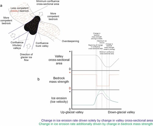
When examining the influence of bedrock mass strength upon overdeepenings (), we represent purely glacial processes using only ice velocity. This is reasonable because ice velocity has the potential to enhance erosion independently, irrespective of the involvement of other processes (such as meltwater erosion and quarrying) and the feedbacks between them – for which there is no data. In turn, confluences can act as a zone of influence (a) in which to test. Where ice encounters a valley confluence (i.e. an effective decrease in CSA) along its course, there must be a localized increase in ice velocity and a corresponding increase in erosion (Glasser Citation1995; Kessler et al. Citation2008), thus producing an overdeepening (Holtedahl Citation1967; MacGregor et al. Citation2000; Alley et al. Citation2003; Herman and Braun Citation2008). A decrease in competency (i.e. bedrock is jointed/loosened/faulted/sheared) will then accentuate the ice velocity and erosion. Hence, the quarrying process (of which ice velocity is one component) can better exploit the increasingly blocky bedrock by fast glacier sliding, low basal pressures, and the focusing of meltwater (Hooke Citation1991; Hallet Citation1996) – further developing the overdeepening (Haynes Citation1968; Seguinot Citation2008; MacGregor et al. Citation2009). A process diagram for the production of an overdeepening controlled by both confluence valley CSA change and bedrock mass strength change is shown in b.
Figure 8. Schematic profile of two geological overdeepenings showing various lithologies and a structural fault zone, denoting change in bedrock competency. It is expected that structural fault zones and/or lithological zones of weak mass strength will concentrate glacial meltwater and increase ice velocity (via quarrying), thus increasing glacial erosion and developing overdeepenings (Haynes Citation1968; Seguinot Citation2008; MacGregor et al. Citation2009).
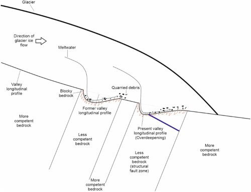
Figure 9. Overdeepening controlled by a combination of ice velocity increase in valley confluence and a reduction in bedrock competency. (a) Schematic plan of a valley confluence that occurs across several lithologies of differing bedrock competency. Where ice encounters a valley confluence (i.e. an effective decrease in CSA) along its course, there must be a localized increase in ice velocity and a corresponding increase in erosion, thus producing an overdeepening (see text). A decrease in bedrock competency will accentuate ice velocity and erosion. Quarrying can then better exploit blocky bedrock – developing the overdeepening (see text). (b) Process diagram for the above. Glacial erosion will scale nearly inversely with valley CSA, resulting in the production of an overdeepening (see and related text). Change in bedrock competency is expected to modify this relationship, amplifying or attenuating overdeepening development (i.e. depth) accordingly.
As discussed by Krabbendam and Glasser (Citation2011), glacial conditions (i.e. ice velocity and thickness) can only be inferred from glacial erosional landforms if the effects of bedrock properties are considered. Glasser and Ghiglione (Citation2009) suggest that the primary control on (overdeepened) fjord development in glaciated areas is geological and not glaciological, with successive glaciations following the same ice-discharge routes; widening and deepening pre-existing geological structures to create the fjord landscape. There is strong evidence for this topographic steering of ice through valley networks (Glasser Citation1995; Alley et al. Citation2003; Herman and Braun Citation2008; Kessler et al. Citation2008; Swift et al. Citation2008; Burschil et al. Citation2019). Towards the Labradorean east coast, ice movement is considered to have been topographically controlled during the late glacial stages (Batterson Citation1990), in what are now the fjordal regions. There is strong evidence for east flowing valley glaciers post-dating northeast-flowing ice on surrounding highlands (Batterson Citation1990; Winsborrow et al. Citation2004; Batterson and Liverman Citation2011).
Analysis in Lloyd (Citation2015) suggests that, at valley scale, bedrock mass strength has no effect on the location of overdeepenings within confluences – regardless of rock type/ faulting. Further, the relationship between confluence CSA ratio and overdeepening depth outside the structural zone is not statistically significant (for each rock type, or taken together) after quality control. However, a statistically significant positive linear relationship (adjusted r2 value of 0.265, p-value of 0.024) is found between overdeepening depths and ice velocity speed-up in confluences in SRTM3 data within the structural zone (). Here, confluence CSA ratio values range from 1.0 to 3.3. Overdeepening depths range between 5 and 16 m, although depths are most commonly between 6 and 10 m. The relationship is not significant within GEBCO data. Findings are based on the 16 SRTM3 observations and 14 GEBCO observations that remain after quality control.
A similar statistically significant positive linear relationship (adjusted r2 value of 0.230, p-value of 0.035) is found between overdeepening depths and ice velocity speed-up in confluences in SRTM3 data within the structural zone () of the Swiss test case, supporting the outcome from the Labrador study and demonstrating that the result is repeatable elsewhere. Confluence CSA ratio values range from 1.1 to 2.7 and so are broadly similar to those encountered in Labrador. The depth of overdeepenings range between 13 and 61 m, although depths are most commonly between 23 and 43 m. Findings are based on the 16 observations that remain after quality control. These depth values correspond with those found in the Swiss study undertaken by Magrani et al. (Citation2020), and similar in Haeberli et al. (Citation2016) and, hence, do not contradict Magrani et al. (Citation2020) who find that overdeepenings in weak bedrock tend to be shallower than those found elsewhere. Depth values from our Swiss study are significantly greater in magnitude than in our Labradorean case. We suggest that the difference in depths may be attributed to the respective stages of orogenic development. The Swiss Alps are a geologically recent mountain range and as such have experienced intense tectonic and isostatic uplift (Froitzheim et al. Citation1996; Champagnac et al. Citation2007). In contrast, the Labradorean case incorporates a geologically ancient denuded craton that has experienced minimal uplift in the east and north during recent geological time (Staiger et al. Citation2005; Occhietti et al. Citation2011).
In summary, evidence from this study supports the view that overdeepening depths scale with ice velocity speed-up in confluences when bedrock is sufficiently weak (i.e. in structural/fault zone). We suggest that this is because of the greater potential for erosion and removal of material in such circumstances. The relationship in Labrador is modest in terms of the magnitude of depth values (being only slightly above the 5 m depth threshold used to identify the overdeepenings), but is statistically significant. Hence, results are valid but should be treated with caution. The relationship is scale dependent, only being observed at local (confluence) scale using SRTM3 data. The relationship is not detected at regional (very large valley, to ice sheet) scale, using GEBCO data, where presumably other controls dominate. In the Swiss replicability test, the relationship is similarly observed at local scale.
4.1 Future research
Previous studies have shown, implied or speculated the existence of various types of overdeepening (Bakker Citation1965; Aniya and Welch Citation1981; Hallet et al. Citation1996; MacGregor et al. Citation2000; Spedding and Evans Citation2002; Preusser et al. Citation2010). Outcomes from this investigation indicate the existence of types of overdeepening other than the confluence type, occurring within and outside glacial valleys, the latter occurring at a variety of (glacial valley to ice sheet) scales which should be investigated further (Lloyd Citation2015).
In this study, no evidence has been found to suggest that overdeepenings are larger in glacial valley confluences – where there is greatest ice velocity speed-up and where ice erosion should be greatest. It is reasonable to expect that this relationship might be found, and it is therefore suggested that the relationship may simply be obscured as a result of another control or series of controls. Such controls might influence the location and size of confluence co-located overdeepenings at local and/or regional scales – most likely operating distally to the confluence. If the effects of such a control can be isolated (i.e. by using subsets of data) then it may be possible to identify a relationship and to discover the influence of the control. This should be examined. Further to this, secondary controls upon overdeepening location and size within confluences should be investigated using the same technique. By way of example, no evidence has been found in this study that maximum ice velocity occurs up-glacier of the location of minimum CSA within confluences. It might be expected that ice flow in this part of a confluence would become less affected by bed and lateral drag, with consequent increase in ice velocity. This is a potential secondary control that could be explored in future.
Similarly, despite the co-location relationship, no evidence has been found to suggest that overdeepenings preferentially occur in confluences situated within weaker bedrock. Here, there should be greater potential for erosion and removal of material. It is possible that such a relationship is obscured because the range in strength of rock types within the zone is not large enough to reveal differences. The change in confluence allometry due to ice erosion (Lloyd Citation2015) will have the effect of reducing the ice velocity speed-up that is apparent for confluences within the structural zone. This could potentially mask any relationship, should the frequency distribution of confluence speed-up be compared within and outside the structural zone. Investigation should assess other study regions and bigger datasets. Most importantly, results should be considered in the light of outcomes of further hypothesis testing using more sophisticated datasets as discussed below.
Further investigation of the influence of bedrock mass strength upon overdeepening location and size should explore not simply ice velocity, but also meltwater abundance and the more complex process of glacial quarrying. These processes should be examined within whole geological zones (not just within confluences), especially within structural fault zones. The acquisition of data regarding quarrying rates is therefore fundamental to further work in this area. Such data should have good spatial coverage.
This investigation has implications for landscape evolution modelling. Results indicate that such models should scale erosion with ice velocity. However, it might be better to formulate better implementations of quarrying, noting that quarrying is thought to depend upon water abundance/pressure and not just ice velocity (Herman and Braun Citation2008; Herman et al. Citation2011).
5. Conclusions
This study demonstrates strong evidence that overdeepenings are preferentially located in glacial valley confluences because this is where ice velocity speed-up occurs due to a downstream reduction in glacial valley cross-sectional area (CSA). This investigation is the first quantitative demonstration that overdeepenings exist in confluences and is important for understanding glacial erosion because it is a rare actual demonstration of the oft-assumed relationship that scales increased erosion with increased ice velocity. The findings reported here therefore provide support for glacial landscape evolution models that, in the absence of a fuller process treatment, scale erosion with ice velocity.
Our findings suggest that structural weakness (i.e. faulting) in bedrock is a primary control upon overdeepening depth within glacial confluences. From this, we infer that removal of eroded material is more effective in confluences within zones of structural weakness. The relationship is true only at local (confluence) scale. The relationship has not been found to occur at regional scale (i.e. very large valley, to ice sheet scale) where presumably other controls dominate.
As discussed by Krabbendam and Glasser (Citation2011), bedrock properties are known to control landform development, but this has rarely been analyzed quantitatively. Here we have shown that fault zones allow more effective erosion, resulting in valley widening and deepening, than is the norm within otherwise generally massive crystalline igneous and metamorphic rocks. This implies that quarrying (plucking) plays a more important role in erosion within zones of structural weakness than does glacial abrasion. This is thought to be because joint spacing favours quarrying over abrasion.
We conclude that reduction in CSA through confluences is a primary control upon overdeepening location, and that variations in bedrock mass strength exert a control on the overdeepening depth within zones of structural weakness. This latter finding is corroborated by findings in another test region.
Acknowledgements
Conceptualization, C.T.L., C.D.C., D.A.S.; methodology, C.T.L., C.D.C., D.A.S.; software, C.T.L., C.D.C., D.A.S.; formal analysis, C.T.L.; investigation, C.T.L.; resources, C.T.L., C.D.C., D.A.S.; writing – original draft preparation, C.T.L.; writing – review and editing, C.T.L., C.D.C., D.A.S.; supervision, C.D.C., D.A.S.; project administration, C.T.L.; funding acquisition, C.D.C. All authors have read and agreed to the published version of the manuscript.
Disclosure statement
No potential conflict of interest was reported by the authors.
Additional information
Funding
Notes on contributors
Christopher T. Lloyd
Dr. Christopher T. Lloyd is a Research Fellow in GIS at the University of Southampton, UK, working within the WorldPop Programme. He conducts high impact research upstream of the WorldPop team's core development of human population models and datasets. Outputs are used by governments and other organisations in low and middle income countries to inform policy and resolve global development problems.
Chris's work focuses on leading production of geospatial datasets using open source methods, with a particular emphasis on the classification of building use via machine learning. These datasets are in essence digital maps that offer a range of geographical information (i.e. buildings, lights at night, accessibility, landcover, climatic, etc.) and act as essential inputs to population modelling. Building classification datasets additionally directly inform development policy in the context of urban planning, resource allocation, and service delivery. His role involves advising (internally and externally with project partners) re. the production and analysis of geospatial data as required in multiple research and implementation projects. Chris produces geospatial software, written training materials targeted at external GIS professionals, and provides PhD supervision. Chris completed his PhD in Glacial Geomorphology and GIS at the University of Sheffield, UK, in 2015.
Chris D. Clark
Prof. Chris D. Clark is Sorby Chair of Geoscience at the University of Sheffield, UK. His primary research interest is in glacial geomorphology, in particular the understanding of processes that lead to the formation of subglacial bedforms (drumlins, flutes etc), and the inverse solution that uses the pattern and distribution of such landforms to reconstruct the behaviour of ice sheets that existed during the last glaciation. His work aims to build a detailed picture of the evolution of former ice sheets through the last glacial cycle and to use this information to improve both ice sheet and climate models.
Chris led the major ‘BRITICE CHRONO' NERC consortium project, the focus of which was to date the retreat of the former British-Irish Ice Sheet and to learn how rapidly ice has retreated across the continental shelf and across the marine-to-terrestrial transition. This knowledge is being used to improve and develop numerical ice sheet models that predict changes in our existing ice sheets. The British-Irish Ice Sheet is now the world's most well constrained retreating ice sheet.
Chris currently leads PALGLAC, funded by the European Research Council. By focussing on the most numerous and spatially-extensive records of palaeo ice sheet activity - glacial landforms - this project aims to revolutionise understanding of past and future ice sheets. The project will vastly increase the available record for tuning or validating ice sheet models, allow development of new tools for gathering landform and geochronological information, and establish procedures for integrating these into ice sheet modelling experiments.
Highlights of Chris's research are:
Mega-scale glacial lineations
Ice sheet reconstructions
Palaeo ice streams
The British-Irish Ice Sheet - BRITICE-CHRONO
Drumlins
Chris completed his PhD entitled, ‘Reconstruction of the behaviour of the Laurentide Ice Sheet using satellite imagery' in 1990 at the University of Edinburgh, UK. He currently lectures on Glacial Geomorphology and Glaciology, and on GIS.
Darrel A. Swift
Dr. Darrel A. Swift is Senior Lecturer in Geoscience at the University of Sheffield, UK. His research interests focus on glacial processes in high-latitude and high-elevation landscapes. These processes (in particular glacial erosion and incision) have played a critical role in the long-term evolution of Earth's climate and evolution of such landscapes. In turn, relevant feedbacks have further affected the behaviour of Earth's glaciers and ice sheets.
Darrel's interests are focussed into several strands that span contemporary glaciology and the long-term erosion and evolution of such landscapes, including: the processes of glacial erosion and sediment transfer through glacial systems; the subglacial hydrology and flow dynamics of contemporary glaciers; and the tectonic and climatic controls on the evolution of alpine and passive margin environments. His current research focuses on sediment transfer by glaciers in Iceland and the European Alps, the influence of bed topography on subglacial hydrology and flow dynamics of mountain glaciers and ice sheet outlet glaciers, and the morphology and formation of subglacial overdeepenings.
Darrel completed his PhD entitled, ‘Provenance of suspended sediment in subglacial drainage systems' in 2002 at the University of Glasgow, UK. He currently lectures on glaciology and glacial geomorphology.
References
- Alley RB, Lawson DE, Larson GJ, Evenson EB, Baker GS. 2003. Stabilizing feedbacks in glacier-bed erosion. Nature. 424(6950):758–760.
- Aniya M, Welch R. 1981. Morphometric analyses of Antarctic cirques from photogrammetric measurements. Geografiska Annaler: Series A, Physical Geography. 63(1-2):41–53.
- Bakker JP. 1965. A forgotten factor in the interpretation of glacial stairways. Zeitschrift fur Geomorphologie. 9:18–34.
- Batterson MJ. 1990. Quaternary geology and glacial history of Labrador: an overview. Geology of Labrador. St. Johns.CERR/ Department of Earth Sciences, Memorial University of Newfoundland.
- Batterson MJ, Liverman DGE. 2011. Contrasting styles of glacial dispersal in Newfoundland and Labrador: methods and case studies. Geological Society, London, Special Publications. 185(1):267–285.
- Bo S, Siegert MJ, Mudd SM, Sugden D, Fujita S, Xiangbin C, Yunyun J, Xueyuan T, Yuansheng L. 2009. The Gamburtsev mountains and the origin and early evolution of the Antarctic Ice Sheet. Nature. 459(7247):690–693.
- Boulton GS. 1996. Theory of glacial erosion, transport and deposition as a consequence of subglacial sediment deformation. J Glaciol. 42(140):43–62.
- Buoncristiani J, Campy M. 2011. Quaternary glaciations in the French Alps and Jura. In: Ehlers J, Gibbard PL, Hughes PD, editor. Quaternary glaciations - extent and chronology, a closer look. Oxford: Elsevier; p. 117–126.
- Burschil T, Tanner DC, Reitner JM, Buness H, Gabriel G. 2019. Unravelling the shape and stratigraphy of a glacially-overdeepened valley with reflection seismic: the Lienz Basin (Austria). Swiss J Geosci. 112(2-3):341–355.
- Champagnac JD, Molnar P, Anderson RS, Sue C, Delacou B. 2007. Quaternary erosion-induced isostatic rebound in the western Alps. Geology. 35:195–198.
- Cook SJ, Swift DA. 2012. Subglacial basins: their origin and importance in glacial systems and landscapes. Earth Sci Rev. 115(4):332–372.
- Cormier CA, Vernon JH, H JrRB. 1998. Sunapee, New Hampshire bedrock well project saves nearly $1,000,000. Journal of the New England Water Works Association. 112(1):70–74.
- Davenport PH, Nolan LW, Wardle RW, Stapleton GJ, Kifoil GJ. 1999. Newfoundland dept. of mines and energy. geological survey. report 99-1. Digital Geoscience Atlas of Labrador. Current Research.[pp. 1-16. 356 p.]. https://www.gov.nl.ca/iet/files/mines-geoscience-publications-currentresearch-1999-davenport.pdf.
- Dühnforth M, Anderson RS, Ward D, Stock GM. 2010. Bedrock fracture control of glacial erosion processes and rates. Geology. 38(5):423–426.
- Egholm DL, Knudsen MF, Clark CD, Lesemann JE. 2011. Modeling the flow of glaciers in steep terrains: the integrated second-order shallow ice approximation (iSOSIA). Journal of Geophysical Research: Earth Surface. 116:F02012. doi:10.1029/2010JF001900.
- Egholm DL, Pedersen VK, Knudsen MF, Larsen NK. 2012. On the importance of higher order ice dynamics for glacial landscape evolution. Geomorphology. 141-142:67–80.
- Fischer UH, Bebiolka A, Brandefelt J, Cohen D, Harper J, Hirschorn S, Jensen M, Kennell L, Liakka J, Näslund J-O, et al. 2021. Radioactive waste under conditions of future ice ages. In: Haeberli W, Whiteman C, editors. Snow and ice-related hazards, risks, and disasters. London: Elsevier; p. 323–375.
- Frey H, Haeberli W, Linsbauer A, Huggel C. 2010. A multi-level strategy for anticipating future glacier lake formation and associated hazard potentials. Natural Hazards and Earth System Sciences. 10(2):339–352.
- Froitzheim N, Schmid SM, Frey M. 1996. Mesozoic paleogeography and the timing of eclogite-facies metamorphism in the Alps: a working hypothesis. Eclogae Geol Helv. 89:81–110.
- Gannett H. 1898. Lake chelan. Natl Geogr Mag. 9:417–428.
- GEBCO. 2003. Centenary edition of the GEBCO digital atlas. User Guide to the GEBCO One Minute Grid. [accessed 2021]. http://www.gebco.net/data_and_products/gridded_bathymetry_data/documents/gridhelp.pdf.
- GEBCO. 2009a. General Bathymetric Chart of the Oceans GEBCO_08 30 arc-second data. [accessed 2021]. https://www.gebco.net/data_and_products/historical_data_sets/.
- GEBCO. 2009b. General Bathymetric Chart of the Oceans GEBCO_08 Grid (30 arc-second) documentation. [accessed 2021]. http://www.gebco.net/data_and_products/gridded_bathymetry_data/documents/gebco_08.pdf.
- GEBCO, IHO, IOC. 2014. The IHO-IOC GEBCO Cookbook. September 2014 ed: IHO, IOC; [accessed October 2014]. http://www.star.nesdis.noaa.gov/sod/lsa/GEBCO_Cookbook/documents/CookBook.9.3.14.pdf.
- Gegg L, Deplazes G, Keller L, Madritsch H, Spillmann T, Anselmetti FS, Buechi MW. 2021. 3D morphology of a glacially overdeepened trough controlled by underlying bedrock geology. Geomorphology. 394:107950.
- Gilbert GK. 1877. The geology of the henry mountains. Washington D.C: US Government Printing Office.
- Glasser NF. 1995. Modelling the effect of topography on ice sheet erosion, Scotland. Geografiska Annaler: Series A, Physical Geography. 77(1-2):67–82.
- Glasser NF, Ghiglione MC. 2009. Structural, tectonic and glaciological controls on the evolution of fjord landscapes. Geomorphology. 105:291–302.
- Gower CF. 1996. The evolution of the Grenville province in eastern Labrador, Canada. Geological Society, London, Special Publications. 112:197–218.
- Gudmundsson GH, Iken A, Funk M. 1997. Measurements of ice deformation at the confluence area of Unteraargletscher, Bernese Alps, Switzerland. J Glaciol. 43(145):548–556.
- Haeberli W, Linsbauer A, Cochachin A, Salazar C, Fischer UH. 2016. On the morphological characteristics of overdeepenings in high-mountain glacier beds. Earth Surf Processes Landforms. 41(13):1980–1990.
- Hallet B. 1996. Glacial quarrying: a simple theoretical model. Ann Glaciol. 22:1–8.
- Hallet B, Hunter L, Bogen J. 1996. Rates of erosion and sediment evacuation by glaciers: a review of field data and their implications. Glob Planet Change. 12:213–235.
- Haynes VM. 1968. The influence of glacial erosion and rock structure on corries in Scotland. Geografiska Annaler: Series A, Physical Geography. 50(4):221–234.
- Herman F, Beaud F, Champagnac J-D, Lemieux J-M, Sternai P. 2011. Glacial hydrology and erosion patterns: a mechanism for carving glacial valleys. Earth Planet Sci Lett. 310:498–508.
- Herman F, Braun J. 2008. Evolution of the glacial landscape of the Southern Alps of New Zealand: insights from a glacial erosion model. Journal of Geophysical Research: Earth Surface. 113:F02009. doi:10.1029/2007JF000807.
- Holtedahl H. 1967. Notes on the formation of fjords and fjord-valleys. Geografiska Annaler: Series A, Physical Geography. 49(2-4):188–203.
- Hooke RL. 1991. Positive feedbacks associated with erosion of glacial cirques and overdeepenings. Geol Soc Am Bull. 103(8):1104–1108.
- Hooyer TS, Cohen D, Iverson NR. 2012. Control of glacial quarrying by bedrock joints. Geomorphology. 153-154:91–101.
- Kessler MA, Anderson RS, Briner JP. 2008. Fjord insertion into continental margins driven by topographic steering of ice. Nat Geosci. 1:365–369.
- Krabbendam M, Glasser NF. 2011. Glacial erosion and bedrock properties in NW Scotland: abrasion and plucking hardness and joint spacing. Geomorphology. 130:374–383.
- Linsbauer A, Paul F, Haeberli W. 2012. Modeling glacier thickness distribution and bed topography over entire mountain ranges with glabtop: application of a fast and robust approach. Journal of Geophysical Research: Earth Surface. 117:F03007. doi:10.1029/2011JF002313).
- Linton DL. 1963. The forms of glacial erosion. Transactions of the Institute of British Geographers. 33:1–28.
- Lloyd CT. 2015. White Rose eThesis Online; Controls upon the location and size of glacial overdeepenings. PhD thesis, University of Sheffield. http://etheses.whiterose.ac.uk/8846/1/Christopher%20Lloyd%20Thesis%20march2015.pdf.
- MacGregor KR, Anderson RS, Anderson SP, Waddington ED. 2000. Numerical simulations of glacial-valley longitudinal profile evolution. Geology. 28(11):1031–1034.
- MacGregor KR, Anderson RS, Waddington ED. 2009. Numerical modeling of glacial erosion and headwall processes in alpine valleys. Geomorphology. 103(1):189–204.
- Mackin JH. 1948. Concept of the graded river. Geol Soc Am Bull. 59(5):463–511.
- Magrani F, Valla PG, Gribenski N, Serra E. 2020. Glacial overdeepenings in the Swiss Alps and foreland: spatial distribution and morphometrics. Quat Sci Rev. 243:106483.
- Makos M, Nitychoruk J, Zreda M. 2013. Deglaciation chronology and paleoclimate of the Pieciu Stawów Polskich/Roztoki Valley, high Tatra Mountains, Western Carpathians, since the Last Glacial Maximum, inferred from 36Cl exposure dating and glacier-climate modelling. Quat Int. 293:63–78.
- Malyutkin BV, Molokov LA. 1985. Engineering-geological conditions of construction of the Shamkhor hydro development on the Kura River. Hydrotech Constr. 19(3):118–124.
- Millan R, Mouginot J, Rabatel A, Jeong S, Cusicanqui D, Derkacheva A, Chekki M. 2019. Mapping surface flow velocity of glaciers at regional scale using a multiple sensors approach. Remote Sens (Basel). 11(21):2498.
- Morlighem M, Rignot E, Mouginot J, Seroussi H, Larour E. 2014. Deeply incised submarine glacial valleys beneath the Greenland ice sheet. Nat Geosci. 7(6):418–422.
- Occhietti S, Parent M, Lajeunesse P, Robert F, Govare E. 2011. Late Pleistocene – Early Holocene Decay of the Laurentide Ice Sheet in Quebec-Labrador. In: Ehlers J, Gibbard PL, Hughes PD, editor. Quaternary glaciations - extent and chronology, a closer look. Oxford: Elsevier; p. 601–630.
- Patton H, Swift DA, Clark CD, Livingstone SJ, Cook SJ. 2016. Distribution and characteristics of overdeepenings beneath the Greenland and Antarctic ice sheets: implications for overdeepening origin and evolution. Quat Sci Rev. 148:128–145.
- Penck A. 1900. Die Uebertiefung der Alpentaler. 12th International Geographical Congress. 2:232–240.
- Pomper J, Salcher BC, Eichkitz C, Prasicek G, Lang A, Lindner M, Götz J. 2017. The glacially overdeepened trough of the Salzach Valley, Austria: Bedrock geometry and sedimentary fill of a major Alpine subglacial basin. Geomorphology. 295:147–158.
- Preusser F, Reitner JM, Schluchter C. 2010. Distribution, geometry, age and origin of overdeepened valleys and basins in the Alps and their foreland. Swiss J Geosci. 103:407–426.
- Rabus BR, Eineder M, Roth A, Bamler R. 2003. The shuttle radar topography mission – a new class of digital elevation models acquired by spaceborne radar. ISPRS J Photogramm Remote Sens. 57:241–262.
- Rodríguez E, Morris CS, Belz JE, Chapin EC, Martin JM, Daffer W, Hensley S. 2005. An assessment of the SRTM topographic products. California: US NASA Jet Propulsion Laboratory, California Institute of Technology; [accessed February 2012]. http://www2.jpl.nasa.gov/srtm/SRTM_D31639.pdf.
- Ross N, Siegert MJ, Woodward J, Smith AM, Corr HFJ, Bentley MJ, Hindmarsh RCA, King EC, Rivera A. 2011. Holocene stability of the Amundsen-Weddell ice divide, West Antarctica. Geology. 39:935–938.
- Sandwell DT, Smith WHF. 1997. Marine gravity anomaly from Geosat and ERS 1 satellite altimetry. Journal of Geophysical Research: Solid Earth. 102:B5. doi:10.1029/96JB03223):10039-10054.
- Schneider JF, Rybach L. 1999. The first deep Quaternary groundwater capture in Switzerland: combined use and environmental benefits. Environ Geol. 39(2):144–148.
- Seaman PG. 1998. Ikaite formation in a fjord environment with special reference to Ikka fjord (unpublished PhD thesis). University of London. Forthcoming.
- Seguinot J. 2008. Glacial quarrying and development of overdeepenings in glacial valleys; Modelling experiments and case studies at Erdalen, Western Norway (MSc dissertation). [accessed 2021]. https://files.osf.io/v1/resources/8fzd6/providers/osfstorage/5b6d217852fa4200165c1416?action=download&direct&version=1.
- Smith WHF, Sandwell DT. 1997. Global seafloor topography from satellite altimetry and ship depth soundings. Science. 277:1957–1962.
- Spedding N, Evans DJ. 2002. Sediments and landforms at Kvı́árjökull, southeast Iceland: a reappraisal of the glaciated valley landsystem. Sediment Geol. 149:21–42.
- Staiger JK, Gosse JC, Johnson JV, Fastook J, Gray JT, Stockli DF, Stockli L, Finkel R. 2005. Quaternary relief generation by polythermal glacier ice. Earth Surf Processes Landforms. 30:1145–1159.
- St-Onge MR, Van Gool JAM, Garde AA, Scott DJ. 2009. Correlation of Archaean and Palaeoproterozoic units between northeastern Canada and western Greenland: constraining the pre-collisional upper plate accretionary history of the Trans-Hudson orogen. London: Geological Society. Special Publications. 318:193–235.
- Sugden DE, John BS. 1976. Glaciers and landscape. A geomorphological approach. London: Arnold.
- Swift DA, Persano C, Stuart FM, Gallagher K, Whitham A. 2008. A reassessment of the role of ice sheet glaciation in the long-term evolution of the East Greenland fjord region. Geomorphology. 97:109–125.
- Swiss Federal Office of Topography (SwissTopo). 2010. Geological Map of Switzerland; 1:500,000 scale, v.1.2. [accessed 2021]. https://www.geocat.ch/geonetwork/srv/eng/md.viewer#/full_view/ca917a71-dcc9-44b6-8804-823c694be516/tab/complete.
- Sykes JF, Normani SD, Yin Y, Sykes EA, Jensen MR. 2009. Hydrogeologic modelling in support of a proposed deep geologic repository in Canada for low and intermediate level radioactive waste. Proceedings of the 12th international conference on radioactive waste management and environmental remediation; Liverpool.
- Talbot CJ. 1999. Ice ages and nuclear waste isolation. Eng Geol. 52:177–192.
- Taylor WP, Wilson CDV. 1997. Tectonically influenced glacial erosion, and ensuing valley infill: a geophysical survey. Q J Eng Geol. 30(2):97–113.
- The Nippon Foundation-GEBCO Seabed 2030 Project. 2022. Mapping progress. British Oceanographic Data Centre (BODC); [accessed 2023 Janaury]. https://seabed2030.org/mapping-progress.
- US NASA. 2005a. Srtm digital elevation – shuttle radar topography mission (SRTM) void filled dataset. US Geological Survey; [accessed 2021]. https://www.usgs.gov/centers/eros/science/usgs-eros-archive-digital-elevation-shuttle-radar-topography-mission-srtm-void?qt-science_center_objects=0#qt-science_center_objects.
- US NASA. 2005b. Srtm digital elevation – shuttle radar topography mission (SRTM) water body dataset. US Geological Survey; [accessed 2021]. https://www.usgs.gov/centers/eros/science/usgs-eros-archive-digital-elevation-shuttle-radar-topography-mission-water-body?qt-science_center_objects=0#.
- Wardle RJ, Gower CF, Ryan B, Nunn GA, James DT, K A. 1997. Geological map of Labrador; 1:1,000,000 scale. Map 97-07. GS# LAB/1226. St. John's: Newfoundland and Labrador Department of Mines and Energy, Geological Survey; [accessed].
- Wardle RJ, Van Kranendonk MJ. 1996. The palaeoproterozoic southeastern Churchill province of labrador-Quebec, Canada: orogenic development as a consequence of oblique collision and indentation. Geological Society, London, Special Publications. 112:137–153.
- Winsborrow MC, Clark CD, Stokes CR. 2004. Ice streams of the Laurentide ice sheet. Geographie physique et Quaternaire. 58(2-3):269–280.
- Yu J, Liu H, Jezek KC, Warner RC, Wen J. 2010. Analysis of velocity field, mass balance, and basal melt of the Lambert Glacier–Amery Ice Shelf system by incorporating Radarsat SAR interferometry and ICESat laser altimetry measurements. J Geophys Res. 115:B11.