
ABSTRACT
Rock discontinuity information plays a key role in engineering activities. In severely fragmented and discontinuous samples, the identification accuracy of rock discontinuities can be improved with the help of geologic knowledge with identified spatial features and geoscience interaction mechanisms. Therefore, we proposed a new method – a knowledge-based intelligent recognition method for rock discontinuities that used point cloud data – to correct inaccurate identification by considering the spatial relationships of rock discontinuities. This paper integrated the geologic knowledge bases in rock discontinuity information extraction rules and combined the generative rule inference model with the region growing method for intelligent extraction. In the case study, we developed four typical rule sets as examples based on the constructed rule system to group rock discontinuities and subsume the fractured rock discontinuities. Results show that this new method is effective in identifying and classifying rock discontinuities of complex areas with a greater reduction in manual intervention.
1. Introduction
Accurate identification of rock discontinuities is critical for geologists in field investigations (Daghigh et al. Citation2022). Geology plays a vital role in slope instability. The structure of geological features affects the sliding of rocks (Gupta, Sanjit, and Josodhir Citation2022). Therefore, the accurate collection and statistics of structural face geometric information is an important issue (Chen et al. Citation2019). However, when the scene is severely fragmented and discontinuous, the rock discontinuity information is difficult to identify accurately from geometric features alone. It requires complex formal representation and reasoning of geologic knowledge (Peppa et al. Citation2019).
Many scholars have deeply analysed and summarized the research on the application of rule sets or knowledge bases (Ballatore, Bertolotto, and Wilson Citation2015; Zhu et al. Citation2017). In terms of the combination of GIS and knowledge rules, Kilpelainen used four types of comprehensive rules, namely, graphic rules, topological rules, relevant context rules and relevant cultural rules, to describe the comprehensive knowledge of topographic maps (Kilpelainen Citation2000); Zhu et al. extracted the geologic ontology from a large amount of geologic literature and open-link data by analysing the natural language processing and data mining algorithms, designed and implemented the knowledge for geologic data mapping framework and corresponding application system. Therefore, by constructing geologic knowledge bases of rock discontinuity information, we can merge the multiple spatial relationships among rock discontinuities and standardize the rules for rock discontinuity information extraction in different geologic environments. This can improve the accuracy and efficiency of recognition in scenarios such as fragmented rock.
Many achievements have been made in structural surface occurrence measurements without the help of geologic knowledge with identified spatiotemporal features and geoscience interaction mechanisms. Rock discontinuity recognition methods are broadly divided into two categories. The first category is based on image data, in which feature points (lines) are extracted after calibrating the image data, and then the occurrence information of the structure face is calculated by a linear transformation formula (Gaich et al. Citation2003; Hadjigeorgiou et al. Citation2003; Lemy and Hadjigeorgiou Citation2003). However, the image data need to be calibrated by control points because of the lack of spatial location information, and the calibration process is inefficient or even impossible in specific cases. And it is more sensitive to light, camera calibration, weather condition, GCP accuracy, Spurious data points for surface without texture (water, snow) than point cloud (H. Li et al. Citation2020). In addition, there is still no universally applicable method for feature extraction (Zheng et al. Citation2022). The second type of method is based on point cloud data, and its identification methods are further divided into two types. The first obtains rock discontinuity information by geometric feature extraction methods on point cloud data (Feng, Vejde, and Jing Citation2003; Gigli and Casagli Citation2011a). The major disadvantage of this method is its high memory consumption and computational cost (Kaiser, Ybanez Zepeda, and Boubekeur Citation2009). The method is also sensitive to segmentation parameters (Awwad et al. Citation2010). The second method involves 3D mesh reconstruction of point cloud data and obtains rock discontinuity information by using point elevation and information such as the normal vector/curvature of triangular surface pieces and then using clustering methods (K-means, fuzzy clustering and the region growing method) (Borrmann et al. Citation2011; Riquelme et al. Citation2014; Slob et al. Citation2005). The significant drawbacks of these algorithms are their sensitivity to noisy data points and their tendency to produce over-segmentation (Hamid et al. Citation2022). These methods cannot be used to accurately identify rock discontinuities that should be of the same type in the extensional direction because point cloud data in discontinuous strata usually contain noise, variable point density, and vegetation cover, which cannot present significant structures (Pu and Vosselman Citation2006; Zhang et al. Citation2018).
The above analysis shows that compared with image data, point cloud data are superior and widely used in the identification and analysis of rock discontinuities due to their high-accuracy spatial location information. However, when the scene is severely fragmented and discontinuous, the existing method requires substantial human intervention to correct the fragmented recognition results. Therefore, we construct knowledge rules to solve this problem by considering the spatial relationship of rock discontinuities to correct inaccurate identification with minor human intervention. Compared with the traditional cluster analysis methods (region growing and K-means algorithms), degree of automation (number of discontinuities requiring manual correction) of the new method decreased by 76.19%.
2. Study area and data preprocessing
To verify the validity and completeness of the proposed method, two study areas are selected: the Ruqin Lake study area and the Tangshan Quarry Park study area. The Ruqin Lake study area is simple since it is used to test the methodology and illustrate the application scenarios and effects of the four rules. The Tangshan Quarry Park study area is used to test the portability of the methodology and the applicability of the developed approach for complex scenarios, with more focus on the overall effects.
2.1. Ruqin Lake study area
2.1.1. Structural characteristics
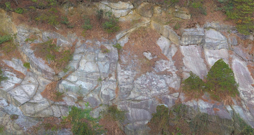
Ruqin Lake is located in Mount Lu, China, which has the structural characteristics of layered geological bodies with multiple genetic complexes. It was formed due to the uplift of the crust of Mount Lushan and other reasons. The study area is located at the mouth of Ruqin Lake. The corresponding 3D scene data in this study case are shown in . Three-dimensional modelling (3D) based on the collected point cloud data clearly shows that the Ruqin Lake study area consists of rock strata and joint planes. The tendency of the dip angle is 29° and the dip direction is 132°.
Figure 1. 3D scene of the exposed profile of Ruqin Lake.
2.1.2. Point cloud data collection process
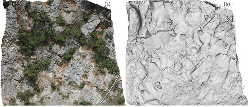
We took the structural characteristics of the outcrop in the Ruqin Lake area of Mount Lu as the research object (length 20 m, width 10 m) and used a DJI Genie 3Pro unmanned aerial vehicle (UAV) for data acquisition combined with context capture for data processing. Geomagic software was used to process the point cloud noise, and ContextCapture software was used to georeference the data using World Geodetic System (WGS84). This testing data set had 260,588 points with a point resolution of approximately 5 mm and covered a 20 m by 10 m area, as shown in . The point cloud was transformed into a triangulated irregular network (TIN) with 1,599, 276 triangular mesh units using the Delaunay algorithm, as shown in .
Figure 2. Ruqin lake ((a) Point cloud data and (b) Triangulated irregular network).
Then, we used the region growing method based on the half-edge structure to preliminarily achieve rock discontinuity feature extraction, which provided the database for the rule engine (Riquelme et al. Citation2014). To improve the efficiency of the algorithm, we implemented the neighbourhood query by finding the triangle data corresponding to the opposite half according to the half-sided chain table.
2.2. Tangshan Quarry Park study area
2.2.1. Structural characteristics
Tangshan Quarry Park is located in Nanjing, China and its geologic structure is mainly composed of sedimentary rock layers. It is mainly composed of limestone. This is the former Longquan Quarry, which was mainly engaged in the open pit mining of limestone. Due to the late geological movement and rock stress, the rock body in the Tangshan Quarry Park study area has developed a relatively dense joint fissure, resulting in a complex and variable rock discontinuities, broken scenes. Considering that the overall geological structure is difficult to understand and observe, we obtains the structural characteristics of the rock body based on expert analysis: The Tangshan Quarry Park study area we have chosen composed of bedding planes and joint planes.
2.2.2. Point cloud data collection process
We used the point data acquired with a Riegl terrestrial laser scanner to scan the steep rocky slopes of Tangshan Quarry Park in China. Scanning was performed from three observation stations that were approximately 10 m apart. The observation stations were approximately 8 m from the rock face. The Riscan software was used to assign WGS84 to the point cloud data based on the following steps. Firstly, Ground Control Points (GCPs) are identified in the point cloud data. Secondly, the precise geographic coordinates of the identified GCPs are entered into the software. Thirdly, conversion and alignment techniques were applied to georeference the point cloud data. Finally, quality control checks are performed to verify the accuracy of the alignment. The joint point cloud from the three observatories had 45,800,549 points with a point resolution of approximately 5 mm. This testing data set covered a 30 m by 30 m area, as shown in . The point cloud was transformed into a TIN with 5,639,664 triangular mesh units using the Delaunay algorithm. Vegetation was filtered through the vegetation index. A vegetation index of between 0 and 1 was defined as the vegetation being able to filter most of the vegetation effectively. Due to the complexity of the area, an expert field surveyed and labelled the rock discontinuities of the study area.
Figure 3. Tangshan quarry park ((a) 3D scene and (b) Triangulated irregular network).
3. Methods
The knowledge-based intelligent recognition method for rock discontinuities consists of three general steps: (1) Acquisition and storage of geologic knowledge: performing a semantic symbolic construction of the existing property and relations between the rock discontinuities; (2) Construction of a rule inference model: converting the semantic-based geologic knowledge base into formalized language that can be enforced by the rule engine in the form of ‘IF-THEN’. (3) Design of the rock discontinuity rule engine: embedding the rock discontinuity rules into the rule file of the rule engine, which carries out the processes of matching rules, triggering agendas, executing DROOLS, and outputting the results.
3.1. Acquisition and storage of geologic knowledge
The rule system constructed in this paper () for identifying rock mass discontinuities includes the following aspects: (1) Surface features: Discontinuities often leave distinctive features on the Earth’s surface. By observing and analyzing these surface features, discontinuities can be identified. From a quantitative perspective, this includes the dip direction, dip angle, spacing, trace length, aperture, and roughness; (2) Contact relationships: The contact relationships between rock discontinuities include topological relationships, adjacency relationships, continuity relationships, and occurrence consistency relationships. By observing and analyzing these contact relationships, areas that conventional clustering methods struggle to accurately identify can be inferred and corrected. (3) Structural features: Discontinuities typically exhibit specific geometric forms, such as faults, joints, and fractures. Faults are fracture surfaces between rock layers. Joints are parallel or nearly parallel fractures within rocks, often arranged in regular or irregular patterns. Fractures refer to irregular cracks within rocks. By observing and measuring the geometric forms of rock masses, discontinuities can be identified. (4) Lithological changes: Discontinuities often cause changes in lithology, such as differences in rock layers on either side of a fault surface. By comparing and analyzing different lithologies, discontinuities can be identified. (5) Geological events: In general, geological events refer to various physical, chemical, and biological processes occurring internally and externally within the Earth. They can be categorized as events of internal force and external force (Pan et al., Citation2016). When identifying discontinuities, it is necessary to consider the impact of geological events and analyze them based on their characteristics.
Figure 4. A system of rules for recognizing rock discontinuities.
It is worth noting that rock faults, joints, and fractures are common geological structural features that play a significant role in the structural integrity and behaviour of rock formations. Here is a additional description of each concept: (1) Rock Faults: Rock faults are planar fractures or zones of weakness in the Earth’s crust where there has been movement along the fault plane. Faults are classified based on the direction of movement relative to the fault plane (e.g. normal faults, reverse faults, strike-slip faults) and can vary in scale from small fractures to large tectonic faults. They are important in geology for understanding the deformation and displacement of rock layers (Bo et al. Citation2020). (2) Joints: Joints are fractures in rocks where there has been no significant movement along the fracture plane. Joints are typically formed in response to stress and can occur at various orientations relative to the rock’s bedding or foliation. They are important in rock mechanics and engineering as they influence rock strength, permeability, and weathering characteristics (Veslud et al. Citation2009). (3) Fractures: Fractures are general terms used to describe any break or crack in a rock mass, encompassing both faults and joints. Fractures can result from a variety of geological processes, including tectonic forces, weathering, and erosion. They can affect the mechanical properties and stability of rock formations and are crucial in various fields such as hydrogeology, geotechnical engineering, and petroleum exploration (Battista et al. Citation2015).
In conclusion, the rule system for identifying rock mass discontinuities includes multiple aspects, such as surface features, spatial relationships, structural features, lithological variations, and geological events. However, the inaccurate recognition ability of existing rock discontinuity methods is mainly caused by displaced and fragmented scenes, which can be solved by constructing knowledge rules concerning the spatial relationship between rock discontinuities. Therefore, this paper focuses on the rules derived from the spatial relationships between rock discontinuities. Rock discontinuity knowledge is complex and variable, and expert knowledge and experience are difficult to express quantitatively, so the main task of constructing the geologic knowledge base is to describe and represent the expressible parts of the rock discontinuities using generative rules. The process of constructing the geologic knowledge base in rock discontinuity information extraction is shown in . The properties of rock discontinuities can be collected using existing rock information extraction methods (Awwad et al. Citation2010; Borrmann et al. Citation2011; Riquelme et al. Citation2014; Slob et al. Citation2005; Tarsha-Kurdi, Landes, and Grussenmeyer Citation2008).
Figure 5. Construction of a geologic knowledge base for rock discontinuity information extraction.
To infer effectively, it is necessary to summarize the object properties and relations of the rock discontinuities from the characteristic analysis and formal expression of the structural surface. The information needed for the rule set is described below.
(1) Construction of an object property table of rock discontinuity surfaces.
By comparing and analysing the attribute features, the dominant structural face group can be divided. To facilitate subsequent rule inference, semantic symbolic construction of existing attribute categories is required ().
Table 1. Rock discontinuity object properties.
(2) Expression of relations in the rock discontinuity surface
The spatial relationships between rock elements contain topological, contact, continuity and occurrence consistency relationships. The establishment of these object relationships can help to obtain the object property information through the subsequent rule inference module ().
Table 2. Relationship between rock discontinuity objects.
3.2. Construction of the rule inference model
In this paper, a rule inference model based on ‘IF-THEN’ production rules is used to infer the occurrence information of the rock discontinuities. ‘If A, then B’ or ‘A->B’ is the symbolic description of the generative rule, where A represents the condition, B represents the conclusion or the corresponding related operation, and ‘->’; indicates performing the corresponding operation. It operates as follows.
(1) Input the rock discontinuity information. (2) Compare the input rock discontinuity information with the existing database: If the database already contains the rock discontinuities, the operation will be terminated; otherwise, the operation proceeds to the next step. (3) Input the rules to be used. (4) Compare the input rules with the existing rule set: If an input rule exists in the rule set, execute the currently selected rule and mark it; otherwise, the user further provides the knowledge rule for inferring the rock discontinuity information.
We take discontinuous trace line morphology complementation as an example (). Rule derivation is performed for multiple discontinuous trace line segments to realize the morphological complementation of the blind area of trace lines. A schematic diagram of discontinuous trace morphology completion is shown in , where the dashed line segment indicates the intelligent completion area.
Figure 6. Complementary discontinuity trace lines.
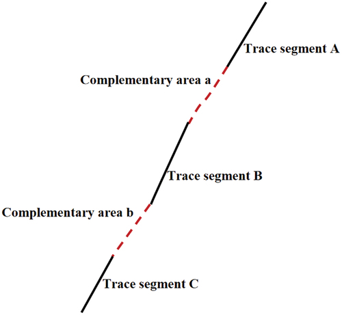
The identification analysis is simplified by expressing the process as follows:
Obtaining the facts:ExposedTypeOf(A)=ExposedTypeOf(B)=ExposedTypeOf(C) = Line;
Inferring to complete the traces:If TopoRelationOf(A,B)=Disjoint And TopoRelationOf (B,C)=Disjoint AndContinuityOf(A,B)=False AndContinuityOf(B,C) =False AndThrendOf(A)=ThrendOf(B)=ThrendOf(C)Then,CreateLine(A,B)CreateLine(B,C)
3.3. Design of rock discontinuity rule engine
The rock discontinuity rule engine is constructed based on DROOLS by combining the spatial relationship rule set and the generative rule inference model. We converted the semantic-based geologic knowledge base into formalized language that can be enforced by the rule engine based on DROOLS. DROOLS is a JBOSS business rule management system to support a Java rule engine API (JSR-94). DROOLS provides a unified and integrated platform for rules, workflow and event processing. DROOLS separates a rule from a business logic that is to be implemented in the application, and only the rule should be changed and applied without changes in programming, even if the business logic is changed. Since the modification and redistribution of a programme are unnecessary, it is easy to develop and manage applications. Therefore, we converted these rules into rule files of the rule engine based on DROOLS, and we modified and redistributed them in real time. Taking four typical rule sets as an example (), this rock discontinuity rule engine first grouped the rock discontinuities and then executed the fractured rock occurrence rules and conformity and pseudoconformity occurrence rules to obtain occurrence information. Then, the occurrence consistency rule was invoked to correct the fragmentation identification results in discontinuous strata. Finally, the information statistics and analysis are performed.
Figure 7. Construction of the rock discontinuity rule engine.
The specific implementation process of the rules is shown in . The initial data, which include point cloud coordinates and rock mass structural attitudes extracted in Section 2, are inputted into the working memory in the form of a txt file. Fact objects are defined for rule matching and inference, which include the dip angle and spatial relationships between rock mass structures. The pattern matcher is used to compare the geologic knowledge rules and data. Once a rule is matched, the rule engine adds the matched rule to the agenda, which is the list of rules to be executed. Additionally, the rule engine interprets the rule file and determines the operations to be executed when the conditions are satisfied. Following the order of rules in the agenda, the rules are executed one by one to extract the rock mass structural features and update the fact base.
Figure 8. Flowchart for the implementation of the knowledge-based intelligent recognition method for rock discontinuities with point cloud data.
4. Case study
4.1. Analysis of rock discontinuity rules
Existing rock discontinuity methods produce inaccurate results due to scene occlusion and fragmentation, which can be addressed by constructing knowledge rules based on spatial relationships between rock discontinuities (Hamid et al. Citation2023). This paper focuses on deriving rules from the spatial relationships between rock discontinuities, particularly emphasizing the recognition of four structural relationships: topological, contact, continuity, and occurrence consistency (Rushikesh et al. Citation2021). The selected four rules serve specific purposes: rock discontinuity grouping rules categorize rock discontinuities, fractured rock occurrence rules address fractured rock layers, conformity and pseudoconformity occurrence rules obtain occurrence information regarding rock discontinuities that cannot be obtained through non-contact acquisition, and occurrence consistency rules identify discontinuities spanning the same type of strata in the extension direction (Sarvesh et al. Citation2022). The four rule set is crucial for effectively visualizing and analysing rock discontinuities, especially in addressing challenges such as noise, varying point densities, and occlusion in point cloud data.
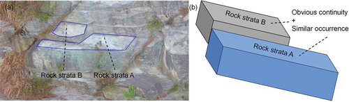
4.1.1. Rock discontinuity grouping rules
The operation of rock discontinuity grouping rules (Appendix A) is based on the idea that the same group of rock discontinuities has similar occurrence information, as shown in . By analysing the occurrence information of each individual surface, the surface is classified into a surface group. When the structural surface cannot be found in the rock discontinuity database, a new structural surface group is created in the rock discontinuity database for that type of structural surface. The rock discontinuity database of the rule engine contains the rock surface ID, dip angle, dip direction, orientation, spatial plane equation parameters, dip angle deviation, dip direction deviation, adjacent rock discontinuities and group. Among them, the adjacent structural surface indicates the spatial relationship between the current structural surface and other rock discontinuities in the threshold range, which is expressed by the structural surface ID. The individual rock discontinuities are classified into the corresponding dominant structural facet groups.And when the identified discontinuities are strongly weathered, they cannot be recognized as rock discontinuities. In this paper, this type of exposed surface is treated by manually correcting the rule set.
Figure 9. Rock discontinuity grouping rules ((a) Study area and (b) Schematic diagram).
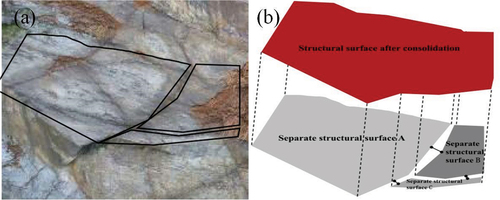
4.1.2. Fractured rock occurrence rules
Fractured rock mass is a geological term, mainly for tectonically affected fractured rock formations. The spacing of fracture rock discontinuities is less than 10 cm (Jing et al., Citation2011; Sampath and Shan Citation2006). The fractured rock discontinuities are different from both block fracture structures and intact structures. Based on this type of structure, we merge the fractured structure based on the following rules (Appendix B): shows the actual fractured rock body, whose separate structural faces have similar occurrence information, and the spacing between the boundaries of each structural face is less than 10 cm. Under this circumstance, the rule engine achieves the merging of fractured structural faces, as shown in .
Figure 10. Occurrence inference of fractured rock ((a) Fractured rock masses and (b) Schematic diagram).
4.1.3. Conformity and pseudoconformity occurrence rules
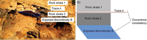
Conformity contact means that the upper and lower strata have no interruption in the sedimentary sequence, the lithology or the contained fossils are consistent or variable, and the occurrence is basically the same due to continuous deposition (Ji et al. Citation2020). The unconformity contact of strata exists as a kind of parallel unconformity contact. It is characterized by basic parallelism between the upper and lower strata, but the age of the two sets of stratum is not continuous, which is reflected in the existence of long-term sedimentary interruption and weathering denudation surfaces between them. The rock discontinuities under conformity and pseudoconformity often have consistent occurrences. The occurrence information of the trace lines can be represented by the known occurrence information of the rock discontinuities (Appendix C), as shown in .
Figure 11. Schematic diagram of conformity and pseudoconformity occurrence rules.
4.1.4. Occurrence consistency rules
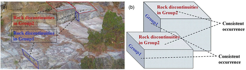
Since discontinuous rock formations are formed for different reasons than their spatial locations, the yield consistency rule can help identify rock discontinuities that should be of the same type of strata in the extensional direction. When a rock discontinuity undergoes significant spatial displacement due to fractures and other reasons, it still has similar yield information. Based on this type of structure, we established an occurrence consistency rule (Appendix D) based on the following knowledge: when the rock discontinuities meet the conditions of similar yield and obvious spatial displacement at the same time, we classify them as the same group of rock discontinuities.
Figure 12. Occurrence consistency rule ((a) Spatial displacement and (b) Schematic diagram).
4.2. Results of the case study
4.2.1. Ruqin Lake study area
Based on the occurrence inference rules developed in section 4.1, this paper realizes the intelligent identification of rock discontinuities. Initially, 27 surfaces were identified with the region-growing method (). The rock discontinuity grouping rules were applied to classify the study area into a group of rock strata with a dip angle of 29° and a dip direction of 132°, and one group of joint plane were observed (). And when the identified discontinuities are strongly weathered and don’t have clear dip direction and dip angle, they cannot be recognized as structural surfaces. In this paper, this type of exposed surface is treated by manually correcting the rule set. The application of the fractured rock occurrence rules subsumed the fractured rock in the number 4 area. The occurrence consistency rules were applied to identify consistent rock discontinuities in the extensional direction, and the surrounding rock areas were grouped accordingly (e.g. 8 and 9). To ensure recognition accuracy, we select outcrop profiles with representative occurrence distributions for data cropping (). According to the structural surface grouping rules, the dominant structural surface grouping results are shown in . Additionally, as verified by the measured data, the identification results presented in this paper are in line with the actual situation and meet the relevant accuracy requirements. Moreover, the identification results for the rock structure features are consistent with the results of expert field surveys.
Figure 13. Rock discontinuities identification results for Ruqin Lake (top view).
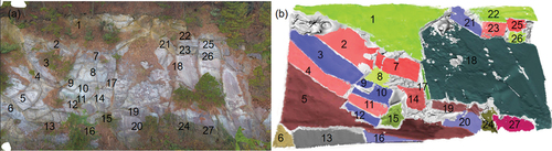
Figure 14. 3D scene of the exposed profile of Ruqin Lake (front view).
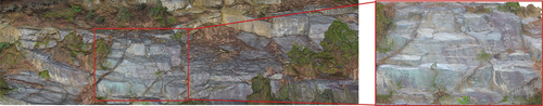
Figure 15. Rock discontinuities identification results of Ruqin Lake study area ((a) Results of applying region growing method and (b) Results of applying rules).
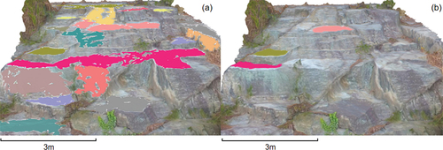
Table 3. Results of the application of the rock discontinuity grouping rules.
Meanwhile, a quantitative analysis of the new method was conducted, and it was found that the method of this paper has the highest accuracy and efficiency compared with the traditional cluster analysis methods (region growing and K-means algorithms). In terms of automation, the number of rock discontinuities requiring manual correction is significantly lower than that of the other two methods ( and ).
Figure 16. Results of the Ruqin Lake ((a) Dip angle and (b) Dip direction).
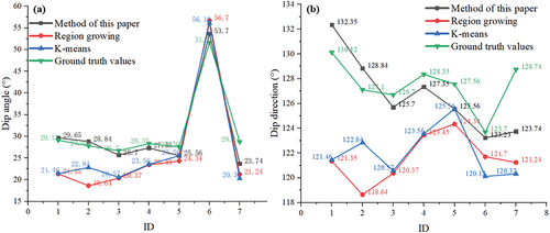
Table 4. Quantitative analysis of the new method in discontinuity estimation.
4.2.2. Tangshan Quarry Park study area
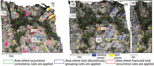
Based on the occurrence inference rules developed in section 4.1, this paper realized the intelligent identification of complex rock structure with a greater reduction in manual intervention. A total of 120 rock discontinuities are identified in this paper by applying region growing method . And it can be observed that the application of the rock discontinuities grouping rules primarily divided the study area into one group of bedding planes (dip direction ranging from 173.67° to 191.88°, dip angle ranging from 51.42° to 55.76°) and one group of joint planes (dip direction ranging from 127.38° to 142.68°, dip angle ranging from 66.02° to 74.19°) . The vegetation area was filtered out and not included in the identification process. It can be seen that the knowledge-based intelligent recognition method removes a large number of non-real structural surfaces such as the exposed surfaces in the green box1. The red-box2 was identified as a fractured zone in the region growing method. Instead, the fractured rock occurrence rule merged the fractured zone by considering the boundaries between its structural surfaces to be within 10 cm. The region growing method only identified multiple rock discontinuities without categorizing them, whereas the proposed method combined the occurrence consistency rule and the rock discontinuities grouping rules to revise rock discontinuities with displacement relationships into rock discontinuities with consistent occurrence with minimal manual intervention (indicated by blue box3). It is worth noting that, verified by the measured data, the identification results of this paper are in line with the actual situation and meet the accuracy requirements. Meanwhile, the identification results are consistent with the experts’ survey. And the number of rock discontinuities requiring manual correction is 25, while region growing and K-means algorithms require 52 and 63 rock discontinuities to be corrected, respectively. What’s more, compared to region growing and K-means algorithms this method improves the accuracy by 17.7% and 16.3% respectively.
Figure 17. Rock discontinuities identification results of Tangshan Quarry Park study area ((a) Results of applying region growing method and (b) Results of applying rules).
5. Discussions
5.1. Features of the methodology
One of the important features of the method is that it groups rock discontinuities using spatial relationships, so the method can reflect the characteristics and developmental patterns of rock discontinuities. The inclusion of expert-identified spatial relationship rules allows the identification results to conform to the objective objects. The second feature is that the determination conditions of the rock discontinuity rule set are based on spatial relationships such as topological, contact, continuity and occurrence consistency relationships among objects. We can obtain these spatial relations from the surface triangular network model based on point clouds, which makes the recognition results relatively accurate. The third characteristic is that the efficiency of the method depends on the extraction rate of the rock discontinuity features, and we can drive the generative rule inference model only after obtaining the attribute features and the relationship between rock discontinuity objects in . In this paper, we implemented rock discontinuity feature extraction based on the region growth method and optimized its computational efficiency by using a half-edge data structure.
The rule-engine-driven rock discontinuity occurrence information extraction method is different from other existing occurrence information extraction methods. It can be applied to engineering applications related to rock discontinuities and be used to extract the occurrence information of rock discontinuity surfaces on a regional scale. However, the method does not consider the interrelationships between factors in the application process, which depend on the surface and internal information of the rock discontinuities. Therefore, improving the inference of the internal structural information of rock masses is still an important research topic.
5.2. Contribution and shortcomings of the methodology
This study is of great significance both from the theoretical perspective of data science and from the perspective of improving the practical application of rock discontinuity information extraction. The main contribution of this paper is to use the spatial relationships among rock discontinuities to construct knowledge rules to solve the problem. Current rock discontinuity information extraction methods require considerable manual intervention for correction due to ignoring spatial correlations. This methodology opened up a new perspective for rock discontinuity information extraction, and the case study showed that this new idea is feasible.
The rock discontinuity information extraction method based on the rule engine is significantly different from that of existing methods because it utilizes spatial relationship rules that are expertly predefined to extract rock discontinuity information. Previously, the application of such knowledge rule sets in rock discontinuity information extraction has never been explored. This study improved the data quality of rock discontinuity information extraction results. The rule set in this paper is not yet able to identify the structural face types, which can be considered using the method of this paper combined with machine learning (H. Li et al. Citation2020; Shi et al. Citation2022). This issue needs to be explored separately for a more effective application of the rock discontinuity information extraction method based on the rule engine. Despite its limitations, the proposed method can extract rock discontinuity information on a regional scale. Additionally, as verified by the measured data, the identification results presented in this paper are in line with the actual situation and meet the relevant accuracy requirements. Moreover, the identified rock structure features are consistent with the results of expert field surveys.
False negatives may occur in the process of reducing misclassification when using rule-based intelligent recognition methods for rock discontinuities in point cloud data. The following are some of the factors that need to be considered when analysing the possibility of false negatives: 1. Complexity of rock discontinuities: Rock structures can be very complex and heterogeneous, with discontinuities exhibiting different orientations, scales, and shapes. Rule-based methods may have difficulty in capturing all possible patterns and variations, leading to false negatives in cases where discontinuities do not conform to predefined rules.2. Threshold Selection: Rule-based methods often rely on thresholds or parameters to categorize discontinuities. Selection of inappropriate thresholds or rules can result in some discontinuities falling below the detection threshold, leading to false negatives. To address the potential false-negative problem in rule-based methods for intelligent identification of rock discontinuities in point cloud data, it is important to conduct thorough validation and testing to assess the performance of the methods and identify potential limitations; fine-tune the rules and parameters based on the specific characteristics of the rock formation and point cloud data.
6. Conclusions
In this study, a new method is proposed for rock discontinuity occurrence information extraction through different spatial relationship rules of rock discontinuities. The article mainly validates the idea that information or knowledge related to rock discontinuities has a certain regularity, so this information can be introduced into the identification and information extraction of rock discontinuities by introducing knowledge rules. The method in this paper first establishes a knowledge rule base and then builds a rock discontinuity rule engine based on the generative rule inference model to group the structure faces for identification. Finally, for rock discontinuities with different spatial relationships, the corresponding inference analysis is used to obtain the occurrence information. The experiments on the extraction of occurrence information in the Ruqin Lake and Tangshan Quarry Park show that this method is effective, and the method achieves fast extraction and intelligent recognition of complex rock discontinuities.
Acknowledgements
The authors express their gratitude to the journal editors and the reviewers, whose thoughtful suggestions played a significant role in improving the quality of this article.
Disclosure statement
No potential conflict of interest was reported by the author(s).
Additional information
Funding
References
- Awwad, T. M., Q. Zhu, Z. Du, and Y. Zhang. 2010. “An Improved Segmentation Approach for Planar Surfaces from Unstructured 3D Point Clouds Photogramm.” Photogrammetric Record 25 (129): 5–23. https://doi.org/10.1111/j.1477-9730.2009.00564.x.
- Ballatore, A., M. Bertolotto, and D. C. Wilson. 2015. “A Structural-Lexical Measure of Semantic Similarity for Geo-Knowledge Graphs.” ISPRS International Journal of Geo-Information 4 (2): 471–492. https://doi.org/10.3390/ijgi4020471.
- Battista, M., C. Dario, A. Antonio. 2015. “Geological Mapping and Fold Modeling Using Terrestrial Laser Scanning Point Clouds: Application to the Dents-du-Midi Limestone Massif (Switzerland).” European Journal of Remote Sensing 48 (1): 569–591. https://doi.org/10.5721/EuJRS20154832.
- Bo, W., S. Huachao, H. Lanying, S. Liu, B. Jin, H. Zhang, Z. Zhang, X. Ding, W. Qiu, and S. Wang. 2020. “Wave Field Characteristics of Small Faults Around the Loose Circle of Rock Surrounding a Coal Roadway.” Journal of Environmental & Engineering Geophysics 25 (2): 245–254. https://doi.org/10.2113/JEEG19-073.
- Borrmann, D., J. Elseberg, K. A. Lingemann, and A. Nüchter. 2011. “The 3D Hough Transform for Plane Detection in Point Clouds: A Review and a New Accumulator Design 3D.” 3D Research 2 (2): 1–13. https://doi.org/10.1007/3DRes.02(2011)3.
- Chen, Z. X., X. A. Ye, W. B. Zhang. 2019. “Formation Mechanism and Stability Evaluation of High Level Dangerous Rock Collapse of Highway in Strong Earthquake Area Based on UAV Tilt Photography.” Journal of Earthquake Engineering 41 (1): 257–267, 270.
- Daghigh, H., D. D. Tannant, V. Daghigh, D. D. Lichti, and R. Lindenbergh. 2022. “A Critical Review of Discontinuity Plane Extraction from 3D Point Cloud Data of Rock Mass Surfaces.” Computers & Geosciences 169:105241. https://doi.org/10.1016/j.cageo.2022.105241.
- Feng, Q., S. Vejde, and L. Jing. 2003. “A New Method for in-Situ Non-Contact Roughness Measurement of Large Rock Fracture Surfaces.” Rock Mechanics & Rock Engineering 36 (1): 3–25. https://doi.org/10.1007/s00603-002-0033-1.
- Gaich, A., M. Pötsch, A. Fasching, and W. Schubert. 2003. “Contact-Free Measurement of Rock Mass Structures Using the JointMetrix3d System.” International Journal of Rock Mechanics & Mining Sciences 41:304–309. https://doi.org/10.1016/j.ijrmms.2004.03.058.
- Gigli, G., and N. Casagli. 2011a. “Semi-Automatic Extraction of Rock Mass Structural Data from High Resolution LIDAR Point Clouds.” International Journal of Rock Mechanics and Mining Sciences 48 (2): 187–198. https://doi.org/10.1016/j.ijrmms.2010.11.009.
- Gupta, N., K. P. Sanjit, and D. Josodhir. 2022. “GIS-Based Evolution and Comparisons of Landslide Susceptibility Mapping of the East Sikkim Himalaya.” Annals of GIS 28 (3): 359–384. https://doi.org/10.1080/19475683.2022.2040587.
- Hadjigeorgiou, J., F. Lemy, P. Côté, and X. Maldague. 2003. “An Evaluation of Image Analysis Algorithms for Constructing Discontinuity Trace Maps.” Rock Mechanics & Rock Engineering 36 (2): 163–179. https://doi.org/10.1007/s00603-002-0041-1.
- Hamid, D., D. T. Dwayne, J. Majid. 2023. “A Computationally Efficient Approach to Automatically Extract Rock Mass Discontinuities from 3D Point Cloud Data.” International Journal of Rock Mechanics and Mining Sciences 172 (3): 1365–1609. https://doi.org/10.1016/j.ijrmms.2023.105603.
- Hamid, D., D. D. Tannant, D. Vahid, D. D. Lichti, and R. Lindenbergh. 2022. “A Critical Review of Discontinuity Plane Extraction from 3D Point Cloud Data of Rock Mass Surfaces.” Computers and Geosciences 169:169. https://doi.org/10.1016/j.cageo.2022.105241.
- Jing, Z. 2011. “Development Techniques of Horizontal Wells in Low Permeability Reservoirs, Jilin Oilfield.” Petroleum Exploration and Development 38 (5): 594–599. https://doi.org/10.1016/S1876-3804(11)60058-X.
- Ji, T., W. Yang, R. Pu, X. Wu, and X. Wu. 2020. “Analysis of Vertical Position Relationships Between Igneous Sills and an Unconformity Surface — Interpretation of Seismic Profiles from the Northern Tarim Basin, NW China.” Interpretation 8 (4): 1–36. https://doi.org/10.1190/int-2019-0129.1.
- Kaiser, A., J. A. Ybanez Zepeda, and T. Boubekeur. 2009. “A Survey of Simple Geometric Primitives Detection Methods for Captured 3D Data.” Computer Graphics Forum 38 (1): 167–196. https://doi.org/10.1111/cgf.13451.
- Kilpelainen, T. 2000. “Knowledge Acquisition for Generalization Rules.” Cartography and Geographic Information Science 27 (1): 41–50. https://doi.org/10.1559/152304000783547993.
- Lemy, F., and J. Hadjigeorgiou. 2003. “Discontinuity Trace Map Construction Using Photographs of Rock Exposures.” International Journal of Rock Mechanics & Mining Sciences 40 (6): 903–917. https://doi.org/10.1016/S1365-1609(03)00069-8.
- Li, H., K. Zhou, L. Mo, A. M. Zain, and F. Qin. 2020. “Weighted Fuzzy Production Rule Extraction Using Modified Harmony Search Algorithm and BP Neural Network Framework.” IEEE Access 8:186620–186637. https://doi.org/10.1109/ACCESS.2020.3029966.
- Pan, P., Z. Wu, X. Feng, and F. Yan. 2016. “Geomechanical Modeling of CO 2 Geological Storage: A Review.” Journal of Rock Mechanics and Geotechnical Engineering 8 (6): 936–947. https://doi.org/10.1016/j.jrmge.2016.10.002
- Peppa, M. V., J. P. Mills, P. Moore, P. E. Miller, and J. E. Chambers. 2019. “Automated Coregistration and Calibration in SFM Photogrammetry for Landslidechange Detection.” Earth Surface Processes and Landforms 44 (1): 287–303. https://doi.org/10.1002/esp.4502.
- Pu, S., and G. Vosselman. 2006. “Automatic Extraction of Building Features from Terrestrial Laser Scanning.” International Archives of the Photogrammetry, Remote Sensing and Spatial Information Sciences 36 (5): 25–27. https://www.isprs.org/proceedings/xxxvi/part5/paper/1219_dresden06.pdf.
- Riquelme, A. J., A. Abellan, R. Tomas, and M. Jaboyedoff. 2014. “A New Approach for Semi-Automaticrock Mass Joints Recognition from 3D Point Clouds.” Computers & Geosciences 68:38–52. https://doi.org/10.1016/j.cageo.2014.03.014.
- Rushikesh, B., Z. Masoud, E. Ebrahim, and J. Sattarvand. 2021. “A State-Of-The-Art Review of Automated Extraction of Rock Mass Discontinuity Characteristics Using Three-Dimensional Surface Models.” Journal of Rock Mechanics and Geotechnical Engineering 13 (4): 920–936. https://doi.org/10.1016/j.jrmge.2021.01.008.
- Sampath, A., J. Shan. 2006. “Clustering Based Planar Roof Extraction from Lidar Data American Society for Photogrammetry and Remote Sensing.” Annual Conference of the American Society for Photogrammetry and Remote Sensing 2006: Prospecting for Geospatial Information Integration, Reno, Nevada, 1262–1267.
- Sarvesh, K. S., P. B. Bikram, R. Simit. 2022. “A Review of Laser Scanning for Geological and Geotechnical Applications in Underground Mining.” International Journal of Mining Science and Technology 33 (2): 133–154. https://doi.org/10.1016/j.ijmst.2022.09.022.
- Shi, D. C., E. Šabanovič, L. Rizzetto, V. Skrickij, R. Oliverio, N. Kaviani, Y. Ye. 2022. “Deep Learning Based Virtual Point Tracking for Real-Time Target-Less Dynamic Displacement Measurement in Railway Applications.” Mechanical Systems and Signal Processing 166:108482. https://doi.org/10.1016/j.ymssp.2021.108482.
- Slob, S., B. Knapen, R. Hack, K. Turner, and J. Kemeny. 2005. “Method for Automated Discontinuity Analysis of Rock Slopes with Three-Dimensional Laser Scanning.” Transportation Research Record. 1913 (1): 187–194. https://doi.org/10.1177/0361198105191300118.
- Tarsha-Kurdi, F., T. Landes, and P. Grussenmeyer. 2008. “Extended Ransac Algorithm for Automatic Detection of Building Roof Planes from Lidar Data Photogramm.” Journal of Finland 21 (1): 97–109. https://www.researchgate.net/publication/228781826_Extended_RANSAC_algorithm_for_automatic_detection_of_building_roof_planes_from_LiDAR_DATA.
- Veslud, C. L. C. D., M. Cuney, G. Lorilleux, J.-J. Royer, and M. Jébrak. 2009. “3D Modeling of Uranium-Bearing Solution-Collapse Breccias in Proterozoic Sandstones (Athabasca Basin, Canada)—Metallogenic Interpretations.” Computers & Geosciences 35 (1): 92–107. https://doi.org/10.1016/j.cageo.2007.09.008.
- Zhang, P., J. Li, X. Yang, and H. Zhu. 2018. “Semi-Automatic Extraction of Rock Discontinuities from Point Clouds Using the ISODATA Clustering Algorithm and Deviation from Mean Elevation.” International Journal of Rock Mechanics and Mining Sciences 110:76–87. https://doi.org/10.1016/j.ijrmms.2018.07.009.
- Zheng, C. C., H. Peng, W. Gang. 2022. “Study on Structural Information Interpretation of Tunnel Fractured Rock and Spatial Spreading Law of Dangerous Rock Collapse.” Journal of Rock Mechanics and Geotechnical Engineering 41 (3): 1–18.
- Zhu, Y., W. Zhou, Y. Xu, J. Liu, and Y. Tan. 2017. “Intelligent Learning for Knowledge Graph Towards Geological Data.” Scientific Programming 2017:1–13. https://doi.org/10.1155/2017/5072427.