
Figures & data
Figure 1. Motion example of the mobile manipulator showing the tasks that must be completed before grasping the object, during the contact, and after carrying it.
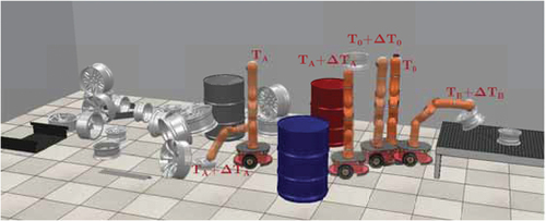
Figure 2. Scheme of the robot with all its frames.
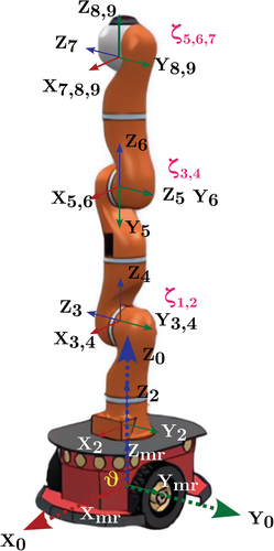
Figure 3. Operating diagram for the MR considering the definition of the hybrid system used in this study.
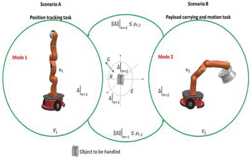
Figure 4. Employed algorithm flow.
Table 1. Initial gain’s condition of the robotic device.
Figure 5. Trajectory tracking for each DoF of the Kuka robot.
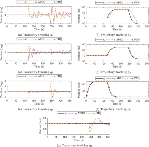
Figure 6. Temporal evolution of the error for each DoF of the Kuka robot.
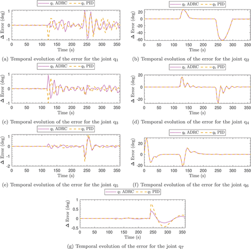
Table 2. Comparison of the mean square error values for the different control laws at each stage for the Kuka robot.
Table 3. Comparison of the error integral values for the different control laws at each stage for the Kuka robot.
Figure 7. Temporal evolution of the error for the PLMR.
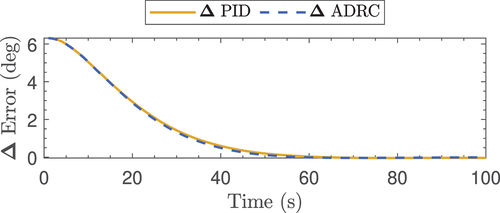
Figure 9. Temporal evolution of the control for each DoF of the Kuka robot.
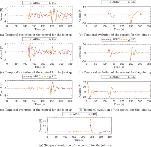
Figure 8. Temporal evolution of the control for the PLMR.
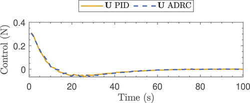
Table 4. Comparison of the mean square control values for the different control laws at each stage for the Kuka robot.
Table 5. Comparison of the control integral values for the different control laws at each stage for the Kuka robot.
Data availability statement
The data that support the findings of this study are available from the corresponding author, [author initials], upon reasonable request.