Figures & data
Figure 1. (a) Stress–strain loop OABCDEO of ideal plastic body (Bridgman, Citation1950). Only the clockwise path is allowed owing to the irreversible character of the plastic deformation. The loop is closed exactly at the starting point O and the identical loop could be repeated indefinitely. The enclosed area of the loop is known as hysteresis loss ().The yield stress and strain are denoted by
and ±
, respectively. The total strain
is composed of two kinds of strain, i.e. elastic (
) and plastic strain (
). (b) Plastic strain
, its increment
and decrement
.
Figure 2. A series of deformed states A, B and C of Figure ) is schematically illustrated. The unstrained body is denoted by O. The yield stress () is given by weight (
). A stopper is set for B to suppress the indefinite extension of the body. PD is observed from A through B.
is the total plastic strain given. All the difference between the states A and B is in their body shapes and no difference in their structures (Section 1.).
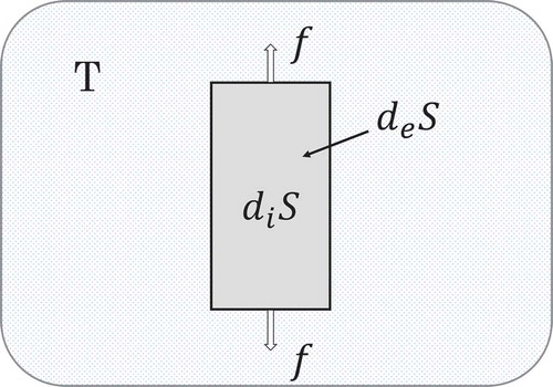
Figure 3. Entropy differential () of the ideal plastic body (darkly shaded). It consists of
and
where the former is due to the irreversible plastic deformation and the latter due to the reversible exchange of energy with the heat bath (slightly shaded). When the heat flows out of the body, the sign of
is taken to be negative. Force
(given by external weight
of Figure ) is applied to extend the body.