
Figures & data
Figure 1. Two CAN-bus connectors with different designs: type A (top) and type B (bottom) (Ojala et al. Citation2017a). (Images are available in colour online)
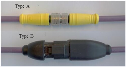
Figure 2. Underground rock drill (Sandvik) and 3-axial accelerometers (Ojala et al. Citation2017a). (Images are available in colour online)
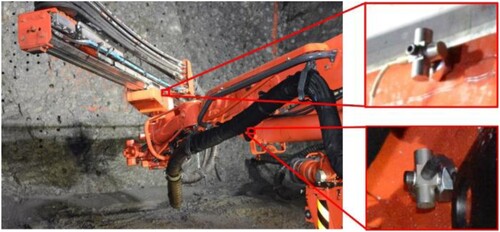
Table 1. Test set-ups.
Figure 3. Schematic drawing of the resonance shaker test. (Images are available in colour online)
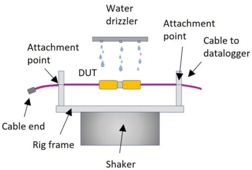
Figure 4. Observed geometry of type B in the resonance shaker test. (Images are available in colour online)
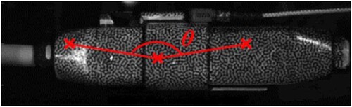
Figure 5. Test samples in the test rig used in the multivariate static test. (Images are available in colour online)
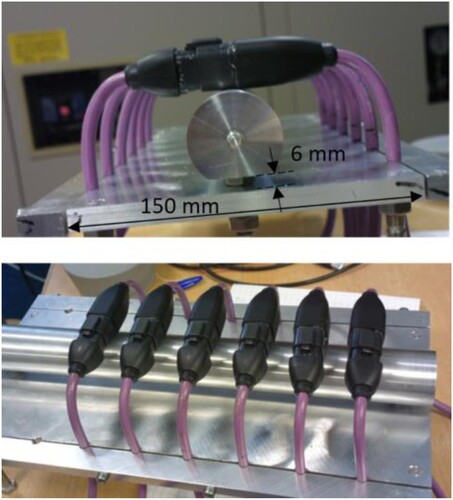
Figure 6. Schematic drawing of the test set-up combining vertical stretching and humidity exposure. (Images are available in colour online)
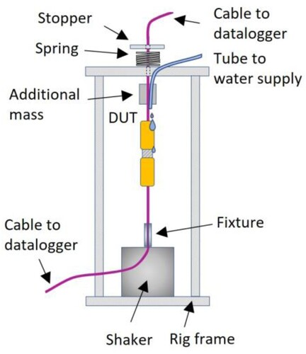
Figure 7. Schematic drawing of the test set-up combining vertical stretching and humidity exposure. (Images are available in colour online)
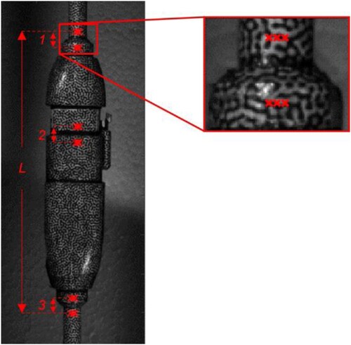
Figure 8. Schematic drawing of the test set-up combining horizontal bending and humidity exposure. (Images are available in colour online)
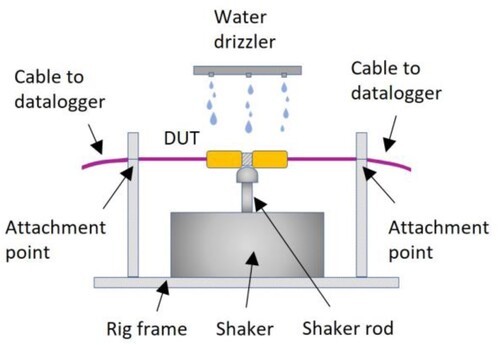
Figure 9. Measurement data of a typical fault of the SC failure mode in the RS test. (Images are available in colour online)
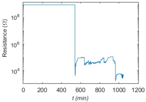
Figure 10. Measurement data of a typical fault of the PT failure mode in the DS test. (Images are available in colour online)
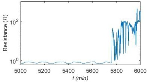
Figure 11. Observation of an intermittent fault in the salt fog (SF) test. (Images are available in colour online)
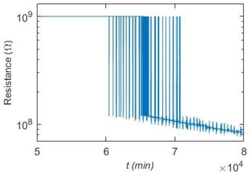
Figure 12. Failure time data of the SC failure mode in the resonance shaker (RS) test. Accelerating variable: Acceleration level of vibration. Failure times marked with a cross (×) and run-out data with a circle (○). (Images are available in colour online)
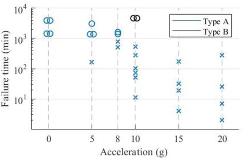
Figure 13. Failure time data of the SC failure mode in the SF test. Accelerating variable: Elevation from the initial position in millimetres. Failure times marked with a cross (×) and run-out data with a circle (○). (Images are available in colour online)
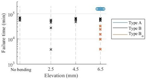
Table 2. Failure time (min) data of the SC and PT failure modes in the dynamic stretching test.
Table 3. Failure time (min) or run-out (ro) time data of the SC and PT failure modes in the dynamic bending test.
Table 4. Deflection under resonance vibration.
Table 5. Component elongation (10−3%) in four locations of the connector in the dynamic stretching test.
Figure 14. Severed signal wire inside the type B connector. (Images are available in colour online)
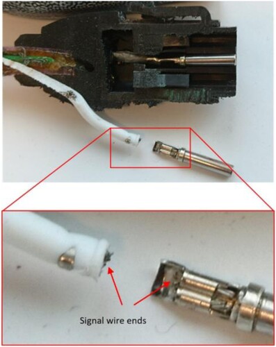
Table 6. Failure times (min) of the first failed samples in tests or run-out (ro) times if no failure occurred, and qualitative comparisons based on observations and high-speed camera measurements.