
Figures & data
Figure 1 Solid 3D model of mandibular first molar. (a) occlusal, (b) lingual, (c) buccal, (d) mesial, and (e) distal surface.
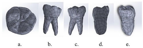
Table 1 Mechanical Properties of Tooth and Restorative Material
Table 2 Mechanical Properties of InterfaceCitation23–28
Figure 2 Stress distribution after vertical loading on lower first molar with MOD cavity and polyethylene fiber reinforced composite on (a) enamel, (b) dentin, (c) packable composite, (d) polyethylene fiber wallpapering the cavity wall, and (e) polyethylene fiber wallpapering the cavity floor.
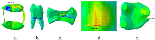
Figure 3 Stress distribution of interface between enamel and packable composite, after vertical loading on lower first molar with MOD cavity+Polyethylene fiber reinforced composite: (a) occlusal view, (b) buccal view of packable composite.
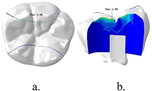
Figure 4 Stress distribution after lateral loading on lower first molar with MOD cavity and polyethylene fiber reinforced composite on (a) enamel, (b) dentin, (c) packable composite, (d) polyethylene fiber wallpapering the cavity wall, and (e) polyethylene fiber wallpapering the cavity floor.
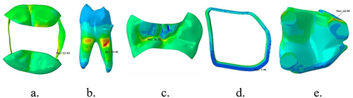
Figure 5 Stress distribution after vertical loading on lower first molar with MOD cavity and e-glass fiber reinforced composite on (a) enamel, (b) dentin, (c) packable composite, (d) e-glass fiber wallpapering the cavity wall, and (e) e-glass fiber wallpapering the cavity floor.
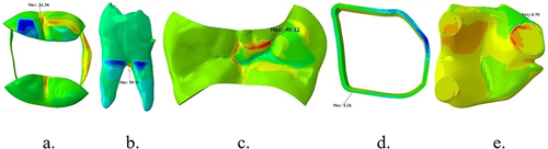
Figure 6 Stress distribution of interface between enamel-packable composite and dentin-fiber e-glass wallpapering the cavity floor after vertical loading on lower first molar with MOD cavity+ e-glass fiber reinforced composite: (a) occlusal of the tooth, (b) buccal of packable composite, (c) occlusal of fiber, and (d) e-glass fiber wallpapering the cavity floor.
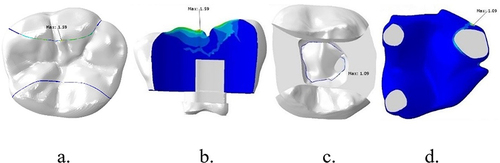
Figure 7 Stress distribution after lateral loading on lower first molar with MOD cavity and e-glass fiber reinforced composite on (a) enamel, (b) dentin, (c) packable composite, (d) e-glass fiber wallpapering the cavity wall, and (e) e-glass fiber wallpapering the cavity floor.
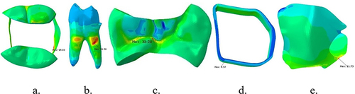
Table 3 Principal Stress for Each Component of Composite Restoration Reinforced with Polyethylene Fiber
Table 4 Principal Stress for Each Component of Composite Restoration Reinforced with e-Glass Fiber
Table 5 Value of Damage Initiation Criterion of Polyethylene Ribbon Fiber-Reinforced Composite
Table 6 Value of Damage Initiation Criterion of e-Glass Ribbon Fiber-Reinforced Composite