Figures & data
Figure 1 Graphic of the spherical harmonic functions up to n=2 on the surface of the unit sphere.
Notes: Here are illustrated the spherical harmonic patterns that gradient shim coils emulate with the Bz field they produce. (The labels X, Y, and Z identify the vectors of cartesian space). MRI terminology identifies n as the shim order, and degree m as one of the (2n +1) linearly independent degenerate functions associated with order n. (It should be noted that this differs from strict mathematical convention).
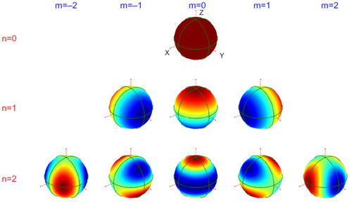
Figure 2 Passive intra-oral shim made of pyrolytic graphite.
Notes: (A), pyrolytic graphite intraoral shim; (B), plastic mold that contained it. Reprinted from NeuroImage, 24(1), Cusack R, Russel B, Cox SM, De Panfilis C, Schwarzbauer C, Ansorge R, An evaluation of the use of passive shimming to improve frontal sensitivity in fMRI, 82–91, Copyright © 2005, with permission from Elsevier.Citation36
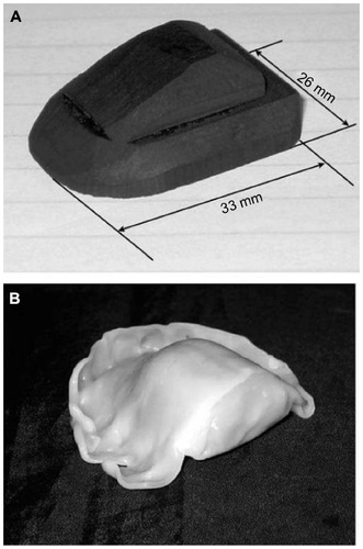
Figure 3 Passive permalloy shim solutions for a second-order shim set.
Notes: 3-D visualization of the second-order spherical harmonic functions X2–Y2, ZX, Z2, ZY, XY (n=2, m=−2, −1, 0, 1, and 2) for a unit sphere (A) and for a unit cylinder (B). In figure part C the red lines represent the theoretically optimized permalloy-shim solutions intended to reproduce the fields seen in the upper two rows, with two pieces of permalloy per shim. Blue lines represent alternate solutions, which allow for minimization of materials at a cost of field accuracy. Reprinted from the Journal of Magnetic Resonance, 183(2), Juchem C, Muller-Bierl B, Schick F, Logothetis NK, Pfeuffer J, Combined passive and active shimming for in vivo MR spectroscopy at high magnetic fields, 278–289, Copyright © 2006, with permission from Elsevier.Citation37
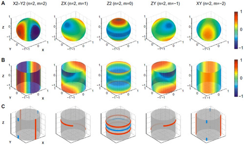
Figure 4 Passive shim assembly for a mouse head.
Notes: (A) Coronal cross section of the mouse-shim system, with rings labeled by letters A to F. (B) Ring cross section, showing ring geometry and ring positions labeled by number. (C) Photograph of constructed shim assembly. (D–F) Optimized ratios and corresponding sheet numbers of bismuth (Bi) to zirconium (Zr). Reprinted from the Journal of Magnetic Resonance, 182(1), Koch KM, Brown PB, Rothman DL, de Graaf RA, Sample-specific diamagnetic and paramagnetic passive shimming, 66–74, Copyright © 2006, with permission from Elsevier.Citation38
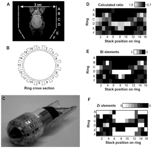
Figure 5 A passive shim assembly for the human head using niobium cylinders.
Notes: (A) Typical optimized locations of niobium cylinders relative to the head. (B and C) Frontal and temporal lobe shim-structure assemblies. The circled numbers identify different components on the frontal lobe assembly. (1) identifies the primary assembly. (2) identifies the mounting structure, and (3) and (4) identify the adjustable controllers, by which the niobium cylinders can be repositioned. (D–F) Assemblies mounted on head coil. Reprinted from Magnetic Resonance Imaging, 29(3), Yang S, Kim H, Ghim MO, Lee BU, Kim DH, Local in vivo shimming using adaptive passive shim positioning, 401–407, Copyright © 2011, with permission from Elsevier.Citation39
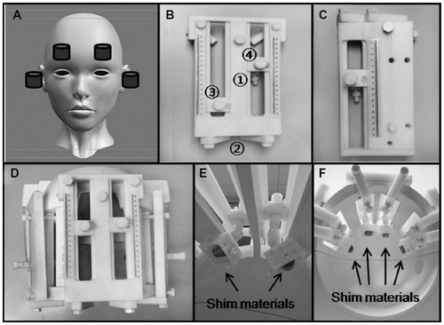
Figure 6 Multicoil active shim assembly for mouse imaging/spectroscropy.
Notes: (A) Schematic of the 48-loop multicoil shim setup. Colors on individual coils indicate an example of coil currents required for the shimming of a mouse brain. (B) Experimental realization of the design. Copyright © 2011 Wiley-Liss, Inc., reprinted from Multicoil shimming of the mouse brain, Juchem C, Brown PB, Nixon TW, McIntyre S, Rothman DL, de Graaf RA, Magnetic Resonance in Medicine, 66(3),893–900.Citation47
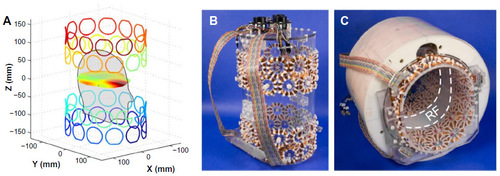
Abbreviation: RF, radio-frequency.
Abbreviation: RF, radio-frequency.

Figure 7 Multicoil shim assembly for the human head.
Notes: (A) Schematic of the 48-loop multicoil shim for a head coil at 7 T. (B and C) Experimental realization of the design. Reprinted from Journal of Magnetic Resonance, 212(2), Juchem C, Nixon TW, McIntyre S, Boer VO, Rothman DL, de Graaf RA, Dynamic multi-coil shimming of the human brain at 7 T, 280–288, Copyright © 2011, with permission from Elsevier.Citation48
Abbreviation: RF, radio frequency.
Abbreviation: RF, radio frequency.