
 ?Mathematical formulae have been encoded as MathML and are displayed in this HTML version using MathJax in order to improve their display. Uncheck the box to turn MathJax off. This feature requires Javascript. Click on a formula to zoom.
Abstract
Modeling of cone-shaped catalytic pellets was performed for irreversible first order reaction by finite element method. Calculations were also made assuming core-shell cone-shaped pellets with inert cores or hollow cone-shaped catalysts immersed in an infinitely large medium. Parameters affecting effectiveness factors (η) such as Thiele modulus (Φ) and cone-angle (β) were studied to compare the results from conventional spherical or cylindrical pellets. An increase of η could be predicted as β increased from cone-shaped pellets. Hollow cone-shaped pellets were also assumed for CSTR to confirm the enhanced performance of the reactor by a larger hollow core for large Φ. As a demonstrative application, cone-shaped pellets with insulated bottoms were considered for analysis of nano-cone arrays by calculating η of the nano-patterns. Assuming pseudo-steady state approximation, unsteady behaviors of reactors containing cone-shaped pellets were predicted for batch and fixed bed reactors by solving reaction-diffusion equations assuming pseudo-steady state approximation. A coated wall reactor with nano-cone arrays could be modeled for the prediction of steady-state concentration in the reaction system. In addition to Φ, β and the number density of nano-cones on the substrate were found to be important factors affecting the performance of the coated wall reactor.
1. Introduction
After the development of catalysts with conventional shapes such as spherical and cylindrical pellets, other morphologies like hollow cylindrical pellets have been studied extensively for enhancement of reactor performance (Nigam et al. Citation1985; Annamalai et al. Citation1999; Hubble et al. Citation2019; Zadeh and Peters Citation2020). For most cases, the effectiveness factor has been considered as important design parameter for the prediction and analysis of reaction systems, providing motivation for significant improvement of the factor by tailoring catalyst morphologies (Pagis et al. Citation2018; Zhu et al. Citation2022). Core-shell particles have also been intensively studied for the modeling of fixed bed reactors, because saving of catalyst cost and large effectiveness factor can be expected from core-shell structures (Li et al. Citation2011; Li et al. Citation2019a). In addition to hollow cylindrical and core-shell pellets, cone-shaped catalysts have been also investigated for oxidation by Monsanto company (Ebner and Keppel Citation1992). However, theoretical researches and numerical studies have not been made yet for such unusual morphologies, compared to other traditional catalyst shapes. Thus, further researches are required for modeling of cone-shaped particles of which the shapes are different from conventional types.
Recently, nanopillar arrays of various components such as metals and ceramics have been prepared by selective growth of the target materials on desirable substrates (Wang and Qi Citation2019; Song et al. Citation2021). Nanorods, hollow nanorods, and nano-cones have been fabricated by controllable aspect ratio for various applications of photocatalysts, electrochemical catalysts, and optical gratings (Zhu and Li Citation2013; Tamirat et al. Citation2016; Li et al. Citation2019b). Though nano-cones have been applied to promote multiphase reaction in flow cell, systematic researches on chemical reactions catalyzed by cone-shaped catalysts have not been carried out by the viewpoint of reaction engineering (Vishwakarma et al. Citation2017). Nano-cone arrays have been fabricated by hydrothermal method for the application of photoelectrochemical reaction to decompose 4-chlorophenol, and superior reaction efficiency over nano-rods has been explained by enhanced charge and mass transfer of nano-cone array (Song et al. Citation2021). However, systematic research on reaction-diffusion phenomena of single cone-shaped catalyst has not been made by the viewpoint of chemical reaction engineering. Thus, an in-depth study of cone-shaped catalyst is essential by solving the reaction-diffusion equation to investigate the effectiveness factor of the pellets, and it is still necessary to develop numerical analyses on catalytic reactors with cone-shaped pellets to predict concentration profiles of reactant in the reaction system.
In the present study, modeling of cone-shaped catalysts was performed for an isothermal irreversible first order reaction to compare the results from cylindrical and spherical particles. The effectiveness factor (η) of cone-shaped particles was calculated by the finite element method, considering Thiele modulus and diffusional resistance in pellets immersed in an infinitely large medium. Factors affecting η were investigated by adjusting Thiele modulus and cone-angle (β). Using calculated values of η, a pseudo-steady state approximation was adopted for analyses of chemical reactors such as batch and fixed bed reactor containing cone-shaped pellets. In addition to isothermal reaction, non-isothermal first order reaction was also considered for modeling and evaluation of η, by solving coupled partial differential equations on concentration and temperature inside cone-shaped pellet numerically. For core-shell and hollow cone-shaped pellets, the thickness of the core was also examined to calculate η for the prediction of the performance of CSTR. The mathematical method was extended for modeling of a coated wall reactor with nano-cone arrays on the substrate by applying insulating boundary condition. Prediction of the concentration profile based on the analytical solution was performed by reflecting the numerical value of surface flux per single cone. Factors such as β and the number density of the nano-cone array were studied for the performance of the reactor. Abundant results on reaction-diffusion phenomena with enhanced effectiveness factor of cone-shaped pellet as unusual catalyst shape can be provided from this manuscript based on the methodology of traditional chemical reaction engineering, which has not been adopted by previous researches on nano-cone arrays.
2. Governing Equations and Computation Methods
2.1. Description of cone-shaped pellets
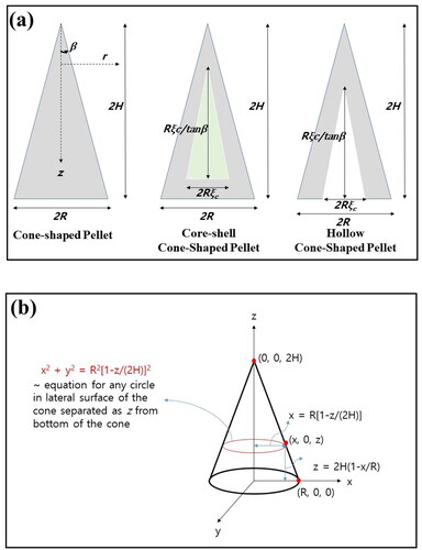
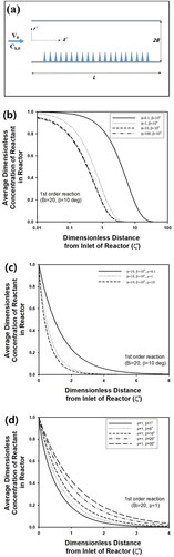
For cone-shaped pellets described schematically in , 2D axi-symmetric geometries were adopted for numerical calculation. Modeling was performed to cone-shaped catalysts to obtain numerical solution by the finite element method. When the radius of the bottom of the cone is fixed as R, the opposite angle can be defined as 2β, where β means the cone-angle of the pellet. As β increased, the height of the cone (2H) increased as R/tanβ. Modeling was also performed to cone-shaped catalysts with insulated bottom and core-shell pellet with inert core as well as hollow cone-shaped particles. For the latter two cases, the half-thickness of inert or hollow cores was defined as Rξc as an adjustable parameter, and cone-angle was defined as β for all particles, as presented in . During finite element calculation, 2D axi-symmetric geometry was constructed to solve governing equations of reaction-diffusion phenomena.
Figure 1. (a) Schematic figure of cone-shaped pellets, core-shell cone-shaped pellets, and hollow cone-shaped pellets. (b) Schematic figure for equation describing lateral surface of the cone-shaped catalyst.
2.2. Effectiveness factor for first-order isothermal reaction
Before the treatment of isothermal reactors, modeling of cone-shaped pellets immersed in an infinitely large medium was performed assuming first-order irreversible kinetics. When the cone was constructed using 2D axisymmetric geometry, the following governing equation can be derived for reactant concentration inside the pellets, cp(r, t).
(1)
(1)
Subject to boundary conditions such as (∂cp/∂r)r=0 = 0, De(∂cp/∂z)z=2H = kf[Cb-cp] on the bottom of cone, and surface flux = kf[Cb-cp] on the surface of cone. Initial condition: cp(r, z, 0)=0
The equation describing the lateral surface of the cone is r = R[1 − z/(2H)]. Because the pellets are surrounded in an infinitely large medium, concentration in surrounding fluid, C0, should be assumed as a constant value. Here, r indicates radial distance from the central line of the pellet, whereas z presents the distance from the top of the pellet. 2H is the height of the pellet, while R indicates half length of the bottom of the pellet. Dr and Dz mean effective diffusivity of reactant along r and z direction, respectively. εp and kf present porosity and mass transfer coefficient, respectively. Because effective and thermal diffusivities can be defined as r and z directions, isotropic medium was assumed for convenience by assuming such parameters are independent to coordinate directions. Thus, non-dimensionalization of the above equation can be performed by defining dimensionless concentration inside pellet and bulk medium as yp(ξ, ζ, τ) and yb (=1), respectively, assuming isotropic medium, as the following manner.
(2)
(2)
subject to boundary conditions such as (∂yp/∂ξ)ξ=0 = 0 and (∂yp/∂ζ)ζ=1 = Bi[1-yp] on the bottom of the cone, and surface flux = Bi[1 − yp] on surface of the cone. Initial condition: yp(ξ, ζ, 0) = 0
Here, ξ and ζ stand for dimensionless distance along r and z direction, respectively. Specifically, ζ is z/(2H), whereas ξ means r/R. In this case, the equation for the lateral surface becomes ξ = 1 – ζ. ΥD means the ratio of effective diffusivity, Dr/Dz, which is 1 for isotropic medium. For isotropic medium, Biot number, Bi, is defined as kfR/De, which means intra-particle resistance divided by external mass transfer resistance, when De is effective diffusivity inside the pellet. Dimensionless reaction time, τ is R2t/De, whereas Thiele modulus, Φ, is R(k/De)0.5. β indicates the cone-angle of the pellet. Though the above equation can be obtained as different manner assuming conical coordinates, 2D axi-symmetric coordinate of ξ and ζ from 0 to 1 is more convenient, when the finite element method is adopt for numerical calculation.
As another approach, modeling of a cone-shaped catalyst can be performed using Cartersian coordinate, and the governing equation can be obtained as the following manner in (x, y, z) space.
(3)
(3)
Subject to boundary conditions such as De(∂cp/∂z)z=2H=kf[Cb-cp] on the bottom of the cone, and surface flux = kf[Cb-cp] on the surface of cone. Initial condition: cp(x, y, z, 0)=0
Here, Dx and Dy indicate the diffusion coefficient of reactant along the x and y axis, respectively. In 3D Cartesian coordinate, any points located on lateral surface of the cone satisfy x2 + y2 = R2[1 − z/(2H)]2, as described in . For isotropic medium, the above equation can be non-dimensionalized as the following manner.
(4)
(4)
subject to boundary conditions (∂yp/∂ζ)ζ=1 = Bi[1 − yp] on bottom of cone, and surface flux = Bi[1-yp] on surface of cone. Initial condition: yp(ξ, ζ, 0) = 0
In this case, the equation describing the lateral surface of the cone can be represented as Here,
and
means dimensionless distance along the x and y axis, respectively (
and
). When the above equation is adopted for finite element calculation, number of the independent variable increases compared to 2D axi-symmetric geometry, implying that it is not advantageous to decrease calculation time by finite element method. Thus, a 2D axi-symmetric structure was employed for the construction of a cone-shaped pellet, and EquationEq. (2)
(2)
(2) was mainly adopted as governing equation of isothermal first order reaction.
2.3. Reactors analyses
For fixed bed reactor, non-dimensional material balance equation for the isothermal first order reaction was solved by pseudo-steady state approximation using calculated values of effectiveness factor from the cone-shaped pellet. For the calculation of η, an infinitely large surrounding medium was assumed at steady state for all calculations. Plug flow was assumed for modeling of fixed bed reactor. For comparison, cylindrical pellets with finite length were considered to calculate η using COMSOL, assuming isotropic medium and neglecting diffusion along azimuthal angle during calculation. For batch reactor and coated wall reactor, analytical solutions were derived from material balance equations to obtain transient concentration and concentration profile inside the reactor.
3. Results and Discussion
3.1 Effectiveness factors of cone-shaped pellets for isothermal first-order reaction
The analytical solution of reaction-diffusion equation in rectangular coordinate shown in EquationEq. (4)(4)
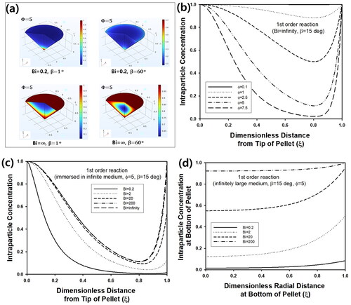
(4) may be obtained by transforming the governing equation in conical coordinate (Moon and Spencer Citation1988). However, it will be more advantageous to solve partial differential equations (PDE) (2) or (4) by numerical method like the finite element method, because the numerical solution can be obtained more convenient manner to analyze reaction-diffusion phenomena from cone-shaped catalyst. Though conical coordinate has been adopted cone-shaped object with ring source to find out analytical solution from the Helmholtz equation in the research area of heat transfer, numerical scheme like finite difference method has been adopted for the analysis of cone-shaped object (Fkiaras Citation1971; Noor et al. Citation2017). Thus, the finite element method was used for evaluation of the effectiveness factor from a cone-shaped catalyst for analysis of reaction-diffusion phenomena in this study. Regardless of β, all predictions were made for ξ and ζ from 0 to 1, because numerical calculation was performed based on PDE as a non-dimensional form. Thus, concentration profiles at stationary state for different cone-angles could be predicted as presented in . For larger β, intra-particle concentration of reactant increased, because the volume of the pellet would decrease for fixed value of R with increasing β, mitigating increase of reactant concentration by inward flux through particle surface. When Bi was small, the intra-particle concentration decreased due to an increase of mass transfer resistance near particle surface. In , the change of intra-particle concentration at steady state was plotted for various Φ as a function of ζ at ξ = 0 inside cone-shaped pellet of β = 15°. Because infinite Bi was assumed during calculation, the dimensionless concentration increased to 1, as ζ approached to 0 or 1 near the surface of the pellet. Compared to the region close to the top of the pellet, the steady-state concentration became much smaller as the position became closer to the bottom of the pellet, because width of the cone increases with an increasing value of ζ, causing increased diffusion length of reactant from surrounding medium. As Φ increased from 0.1 to 7.5, the concentration decreased due to increased reaction rate. For the same pellet, intra-particle concentration was plotted as a function of ξ for various Bi in . As Bi decreased from ∞ to 0.2, the concentration at the bottom of pellet (ζ = 1) decreased from 1 to about 0 due to an increase of external film resistance. On the contrary, the concentration at tip of the pellet was maintained as 1 regardless of Bi, because diffusion length became negligible at the position. For comparison, concentration profile along the bottom of cone was predicted as a function of ξ for various Bi in . Regardless of Bi, the concentration increased as the position changed from the center to surface of the pellet, since reactant from surrounding medium is transferred from surface of the pellet. As Bi increased from 0.2 to 2000, overall concentration increased due to a decrease of external resistance of mass transfer.
Figure 2. (a) Concentration profile of reactant inside cone-shaped pellet at steady state. Bi was 0.2 and ∞, while β was 1 and 60°. (b) Steady-state intra-particle concentration of cone-shaped pellet as a function of ζ at ξ = 0 for various Φ. Bi and β were fixed as 20 and 150, respectively. And intra-particle concentration of cone-shaped pellet as a function of (c) ζ at ξ = 0 and (d) ξ at ζ = 1 at steady state for various Bi. Φ and β were 5 and 15°, respectively.
contains change of effectiveness factor (η) as a function of generalized Thiele modulus (Λ) for a cone-shaped pellet with β = 45° and Bi = ∞, assuming irreversible first order reaction. When the active volume and surface area of catalytic pellet are vp and sp, respectively, the generalized Thiele modulus, Λ, can be defined as vp/sp(k/De)0.5 (Aris Citation1957). For cone-shaped pellet, vp and sp can be calculated as πR2(2H)/3 and πR(2H)(1 + tan2β)0.5 + πR2, respectively, as summarized in . η of the cone-shaped pellet was calculated numerically from average intra-particle concentration at steady state for various mesh conditions during finite element calculations. The results were compared with the internal effectiveness factor, η, of the spherical pellet (red line), which was calculated according to the following equation (Burghardt and Kubaczka Citation1996).
(5)
(5)
Figure 3. (a) Effectiveness factor (η) of cone-shaped pellet with β = 45° as a function of generalized Thiele modulus (Λ) for various mesh sizes. Inset graph contains η vs Φ for β = 45°. (b) η of cone-shaped pellet as a function of Φ for various β, assuming Bi → ∞. Inset graph contains η vs β for Φ = 10. (c) η of cone-shaped pellet as a function of generalized Thiele modulus (Λ), assuming Bi → ∞. (d) η of cone-shaped catalyst with β = 30° for isothermal first order reaction calculated from 2D axisymmetric geometry (red line). Black lines indicate η of the same catalytic pellet constructed as 3D structure. Number of meshes for finite element calculations were varied using normal to extrafine mesh. Inset figure contains cone-shaped catalyst constructed using 3D geometry.
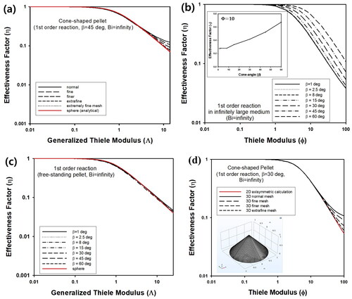
Table 1. Generalized Thiele modulus for simple, core-shell, and hollow cone-shaped pellets.
Here Φ is defined based on radius of the sphere as R, which is the same as the radius of bottom side of a cone-shaped pellet. From vp and sp, Λ of the spherical pellet can be estimated as Λ = Φ/3. Regardless of mesh size, η of cone-shaped pellet was predicted as the same value calculated from the spherical pellet, when Λ was smaller than about 1, as presented in . However, large deviation of effectiveness factor of the cone-shaped pellet was observed, compared to the analytical solution of the effectiveness factor of the spherical pellet for a larger value of Λ, when coarse meshes were used. When extra-fine and extremely fine meshes were used, η of cone-shaped and spherical pellet coincided well each other, implying that smaller meshes can not be adopted for calculation of effectiveness factor of cone-shaped pellets. In this study, extremely fine mesh was chosen for calculation of isothermal condition.
When Bi was ∞, the effect of cone-angle was studied by calculating η as a function of Φ for various values of β, as presented in . Because the volume of the cone-shaped pellet decreases with an increasing value of β for a fixed value of R, the average intra-particle concentration at the stationary state would increase by a continuous supply of reactant from the surrounding medium. Thus, η increased with the increasing value of β, as displayed in the inset graph of . Similar to η of cylindrical pellet with finite length, the data for various values of β shown in can be transformed to η as a function of Λ, and the results should be overlapped as single curve (Aris Citation1957; Cho Citation2023b). As presented in , all effectiveness factors for various β of cone-shaped pellets were predicted as almost single curve, confirming reliable calculation results in . Additionally, η of spherical pellet plotted as a function of Λ indicated as a red line also coincided well with the results of cone-shaped pellets, implying that the prediction of the effectiveness factor in this study would be correct.
As presented in , η of cone-shaped catalyst calculated by finite element method is very similar to η of spherical pellet evaluated using the formula of isothermal first-order reaction, η = {3Λcoth(3Λ) − 1}/(3Λ2), when the generalized Thiele modulus, Λ, is the same. Because errors between two values of η is smaller than 2.7%, the mathematical and numerical approach in this study can be justified because of its accuracy.
Table 2. Effectiveness factors (η) of cone-shaped catalyst (β = 15°) calculated by numerical solution of reaction-diffusion equation as a function of generalized Thiele modulus (Λ) for isothermal first-order reaction.
In this study, most calculations were carried out by constructing cone-shaped catalyst using 2D axisymmetric geometry and solving EquationEq. (2)(2)
(2) , because numerical calculations for 3D structure can be performed within a shorter calculation time. However, the cone-shaped pellet was also constructed using 3D structures as shown in inset figure of to compare numerical values of η obtained by finite element calculations from the 2D axisymmetric structure. As presented using black lines of in , η obtained by solving EquationEq. (4)
(4)
(4) for cone-shaped catalyst with β = 30° (3D structures) was obtained as similar values with the results from 2D axisymmetric geometry. As presented in , the calculated values of η from 3D cone structure became closer to the values from 2D axisymmetric geometry as the number of mesh increased, though calculation time became longer due to the increased number of meshes in 3D geometry. Thus, it can be concluded that 2D axisymmetric geometry can adopted for the analysis of cone-shaped catalyst with a more efficient manner than 3D cone structure.
In this study, non-isothermal reaction was also considered for evaluation of effectiveness factors of cone-shaped catalytic pellet by solving material and energy balance equation using finite element method after non-dimensionalization (Cho Citation2023a). The results was summarized for exothermic and endothermic reactions, including the predictions of intra-particle concentration and temperature profile to demonstrate numerical calculation can be performed for cone-shaped catalysts under non-isothermal conditions, as presented in section A of Supplementary Material.
In addition to the non-isothermal reaction inside a cone-shaped pellet, Langmuir-Hinshelwood (LH) kinetics was also tested to solve another non-linear reaction diffusion equation for a cone-shaped catalyst. As presented in section B of Supplementary Information, the effectiveness factor could be evaluated as a function of generalized Thiele modulus regardless of other parameters of LH kinetics, indicating that numerical solutions in this study is valid for various reaction-diffusion equations.
Because cone-shaped pellets with long aspect ratio can be approximated as one-dimensional object, 1D analysis for the approximation was carried out to evaluate the effectiveness factor of cone-shaped pellet for isothermal first order reaction. As presented in section C of Supplementary Information, the results were deviated from those of more exact 2D analysis in which the cone is constructed as an axisymmetric object, implying that 1D approximation is not adequate for the analysis of cone-shaped pellets unlike analysis of pin in the heat exchanger.
3.2 Case study: analysis of batch catalytic reactor containing cone-shaped catalyst
To demonstrate practical usefulness of the analysis of cone-shaped catalyst, catalytic reactor containing cone-shaped pellets was studied by assuming pseudo-steady state approximation. To this end, calculated values of the effectiveness factor of the cone-shaped pellet can be included in the material balance equation of the chemical reaction system.
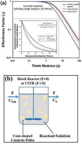
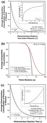
In , η of cone-shaped pellet was compared with those of infinitely long cylindrical and spherical pellets, assuming Bi → ∞. As presented in , η of cone-shaped pellets was always larger than that of cylinder, and η of cone-shaped catalyst was predicted as larger than that of sphere, when β was 8° or 15°, if Φ of cylinder and sphere is defined based on radius R, which is the same radius of bottom side of cone-shaped pellet. The numerical values of η obtained from cone-shaped catalyst can be adopted for analysis of catalytic reactor such as batch reactor and CSTR (continuously stirred tank reactor) described schematically in . Applying pseudo-steady state approximation, the following material balance equation can be derived for the concentration of bulk fluid in a batch reactor, Cb, introducing effectiveness factor, η.
(6)
(6)
Figure 4. (a) Effectiveness factor (η) of cone-shaped, spherical, and cylindrical pellet. Inset graph contains transient concentration of reactant in batch reactor containing three different kinds of the pellets. All calculations were made assuming Bi → ∞. (b) Schematic figure of batch reactor or CSTR containing cone-shaped pellets (Pellet size is not to scale).
Here, VL and VS indicate the volume of reacting fluid and solid catalyst, respectively. KA means the distribution coefficient of the reactant. After non-dimensionalization, the dimensionless concentration of bulk fluid, yb, can be predicted as a function of dimensionless reaction time, τ, as the following manner.
(7)
(7)
In inset graph of , yb was predicted as a function of τ for spherical, cylindrical, and cone-shaped pellet, based on calculation results of η shown in , assuming the same volume fraction of pellets in the reactor (Vs/VL=0.3). Because η of cone-shaped pellets is the most largest among the three catalyst shapes, the most rapid decreasing rate of reactant concentration could be predicted for batch reactor, implying that cone-shaped pellets can be adopted as efficient catalyst morphology for enhancement of reactor performance. Thus, it is possible to shorten reaction time for desired conversion using the same volume of cone-shaped pellets, compared to spherical catalysts in batch reactor.
3.3 Case study: analysis of fixed bed reactor packed with cone-shaped pellet
In addition to batch reactor, performances of fixed bed reactor packed with cylindrical or cone-shaped pellets described schematically in were compared assuming pseudo-steady state approximation. During calculation, the following governing equation was solved to predict reactant concentration in bulk fluid, Cb, after evaluation of η of cylindrical and cone-shaped pellets with an aspect ratio of 1.866 (β = 15 0) (Cho Citation2023b).
(8)
(8)
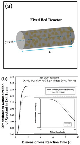
Figure 5. (a) Schematic figure of fixed bed reactor containing cone-shaped pellets (Pellet size is not to scale). (b) Transient concentration of exit stream in fixed bed reactor packed with cylindrical or cone-shaped pellets. During calculation, Vs/VL, KA, β, Dr, Φ, and Pe were fixed as 0.75, 1,15°, 1, and 10, respectively. Aspect ratio of cylindrical pellets was assumed as 1.866, which is the same as cone-shaped pellet with β = 15°.
This equation can be solved analytically to obtain dimensionless bulk concentration, yb, as the following manner.
(9)
(9)
Here, κ is the integration variable. When V0, L, DL, and εb are flowing velocity in a reactor, bed length, dispersion coefficient, and void fraction of the bed, respectively, Pe means Peclet number, u0L/(DLεb), and τ’ is dimensionless reaction time, Dr∙τ, where Dr indicates LεbDe/(u0R2). ζ’ indicates dimensionless bed length, z’/L. a and b are defined as Pe2/4 + Pe∙VS/VLDrФ2KAη, and Pe∙κ, respectively. As presented in , the effluent concentration of a fixed bed reactor packed with a cone-shaped pellet was predicted as a lower value compared to the results of cylindrical pellet, indicating that larger reaction conversion can be expected from a cone-shaped catalyst.
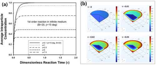
In , transient average intra-particle concentration inside a cone-shaped pellet with β = 15° is predicted assuming Bi = 20 for various Φ from 0.1 to 7.5. As τ increased, the average concentration increased drastically in the initial stage of the reaction, followed by reaching a steady-state concentration, which was affected strongly by Φ. For larger Φ, the steady-state concentration decreased due to increased reaction rate. The transient concentration profile of the reactant inside the pellet was visualized as 3D graphs in . Due to consistent inward flux of reactant through particle surface, cone-shaped pellet was filled with more amount of reactant as τ increased from 0 to 0.04, though the pellet was initially free of reactant at τ = 0. Additionally, it is impossible to predict the concentration distribution of reactant inside the cone-shaped pellet by the approach for evaluation of effectiveness factor using generalized Thiele modulus. However, the concentration profile can be predicted from a mathematical approach based on the finite element method in this study, as shown in . Thus, the numerical approach in this study can be justified for the prediction of intra-particle concentration as well as effectiveness factor.
Figure 6. (a) Change of transient average intra-particle concentration of reactant inside cone-shaped pellet with β = 15° and Bi = 20 for various Φ. (b) Change of reactant concentration inside cone-shaped pellet at τ = 0, 0.01, 0.02, and 0.04. Bi and Φ were fixed as 20 and 5, respectively.
Though the results in this study may be limited for practical uses, useful information can be provided from numerical simulation about cone-shaped catalysts, because experimental studies have been carried out using nano-cone arrays for electrochemistry and fuel cell catalyst (Qiu et al. Citation2014; Khan et al. Citation2015). Thus, practical studies are necessary by comparing modeling and experimental results of cone-shaped catalyst as future researches.
3.4 Effectiveness factors of core-shell or hollow cone-shaped pellets
In addition to simple cone-shaped pellets, core-shell and hollow pellets were also considered for modeling of isothermal first order reaction. For core-shell pellets, the boundary condition at ξ = ξc can be obtained as (∂yp/∂ξ)ξ=ξc = 0, when ξc means dimensionless size of inert-core in cone-shaped pellet, as described in . In , steady-state concentration (ηb) of cone-shaped pellet with inert core was predicted for various values of inert-core thickness, ξc, when Bi and β were ∞ and 15°, respectively. In this case, zero flux of reactant or insulating condition should be satisfied on boundaries between inert core and active catalyst, which can be implemented in COMSOL. Because active catalyst volume decreased with increasing ξc, ηb increased as ξc increased. In inset graph of , change of ηb as a function of generalized Thiele modulus, Λ, was plotted for various value of inert-core thickness, ξc. For core-shell cone-shaped pellets, Λ can be calculated as (Φ/3)(1-ξc3)/{tanβ+(1 + tan2β)0.5}. Regardless of ξc, ηb was predicted as almost the same value, indicating that Λ is a useful parameter to verify effectiveness factor calculated for pellets with complicated shapes. Because ξc means the dimensionless thickness of inert core, ηb can be adopted to calculate the effectiveness factor, η, from the relationship, (Wang and Varma Citation1978; Li et al. Citation2019a). As shown in , η decreased with increasing ξc, implying that the performance of the chemical reactor would decrease, when cone-shaped pellets with inert core are adopted.
Figure 7. Change of (a) steady-state concentration (ηb) and (b) effectiveness factor (η) of core-shell cone-shaped pellet with inert core for various values of ξc. And change of (c) ηb and (d) η of hollow cone-shaped pellet for various values of ξc. For all calculations, Bi and β were ∞ and 15°, respectively. Inset graphs of (a) and (c) present ηb as a function of Λ for core-shell and hollow cone-shaped pellets, respectively. Inset graph of (b) and (d) contains steady-state concentration profile inside core-shell and hollow cone-shaped pellet, respectively, when Bi, ξc, and Φ were ∞, 0.5, and 5, respectively. (e) Transient concentration of reactant in CSTR containing hollow cone-shaped pellet with three different values of ξc. β, Vs/VL, Φ, KA, Cb0, and Ψin were 15°, 0.3, 10, 1, 0, and 10, respectively. Inset graph contains change of ηb as a function of ξc for three different values of Φ such as 1, 5, and 10.
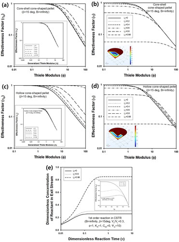
For comparison, ηb of cone-shaped pellet with hollow structure was predicted for various values of Φ, when Bi and β were ∞ and 15°, respectively, as displayed in . In this case, convective boundary condition should be satisfied on the inner surface of hollow cone-shaped pellets like the outer surface of the pellets. During calculation, such boundary conditions could be implemented using COMSOL. Similar to cone-shaped pellet with an inert core, ηb decreased as the hollow volume of the pellet became larger, because catalyst volume decreased with increasing ξc. ηb of hollow cone-shaped pellets could be predicted as almost the same value, when Λ was used instead of Φ, as presented in inset graph of . For hollow particles, Λ can be predicted from (Φ/3)(1 − ξc3)/{(1 − ξc2)tanβ+(1+ξc2)(1 + tan2β)0.5}.
The change of η of hollow cone-shaped pellet as a function of Φ was slightly different from that of core-shell pellet, as presented in . Unlike core-shell cone-shaped pellet with inert core, η of hollow cone-shaped pellet with larger hollow volume increased for large value of Thiele modulus, as ξc increased from 0 to 0.8. This is due to structural difference between the two types of pellets. Since direct mass transfer from the bulk fluid to hollow region is possible for hollow cone-shaped pellets, η can increase due to larger volume of hollow core unlike core-shell pellets with inert cores, especially for sufficiently large value of Φ.
3.5 Case study: analysis of CSTR containing hollow cone-shaped catalyst
In addition to batch and fixed bed reactor, CSTR containing hollow cone-shaped pellets was also considered for modeling. The following material balance equation can be derived for CSTR under isothermal condition.
(10)
(10)
Here, F means volumetric flow rate of fluid, and the above equation can be solved analytically as the following manner after non-dimensionalization.
(11)
(11)
Here, Ψin means dimensionless flow rate of reactant, (F/VL)(R2/De). When Φ is 10, η can be calculated from hollow cone-shaped pellet for here different values of ξc such as 0, 0.6, and 0.98, and the resulting yb(τ) was plotted in . As ξc increased, the concentration of reactant in exit stream of CSTR increased, because active catalyst volume of decreased with increasing ξc, causing a decrease of ηb. As displayed in inset graph of , η increased to maximum at ξc ≅0.6, followed by decrease with increasing ξc, when Φ was 5. Thus, reaction conversion of CSTR at steady state would increase at ξc ≅0.6, compared to conversion by cone-shaped pellet without core (ξc = 0), and decreased again at larger value of ξc like 0.98.
3.6. Effectiveness factors and surface flux of cone-shaped catalytic pellet with insulated bottom
In addition to cone-shaped pellets surrounded by a fluid medium, cone-shaped catalysts with insulated bottom attached to substrate were also considered for modeling of isothermal first order reaction. In this case, boundary condition at bottom of the pellet should be replaced with (∂yp/∂ζ)ζ=1 = 0 in EquationEq. (2)(2)
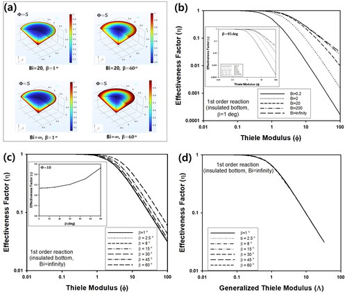
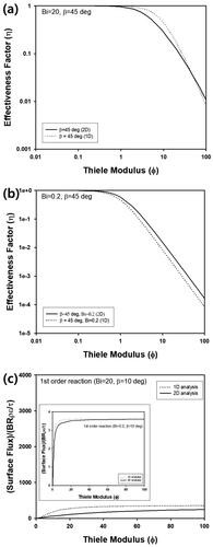
(2) . contains 3D concentration profile inside cone-shaped pellet with insulated bottom at a stationary state. During calculation, Bi was fixed as 20 or ∞, while β was 1 or 60°. Unlike , the reactant concentration at the bottom of cone was not the same as the concentration of surrounding fluid and there existed concentration distribution, when Bi was ∞. This is due to the insulating condition at the bottom, which means the reactant cannot transferred between the bottom and attached substrate. In , η of cone-shaped pellet with insulated bottom at steady state was predicted as a function of Φ for various Bi. Similar to the previous section, η increased as Bi increased from 0.2 to ∞, because external film resistance decreased with increasing Bi. In , η of the cone-shaped catalyst with insulated bottom was calculated as a function of Φ for various values of β. When R is fixed, volume of the pellet would decrease with an increasing value of β, causing an increase of intra-particle concentration inside the pellet. Thus, η increased with increasing β, similar to previous section, as plotted in the inset graph of for Φ = 10. As displayed in , the data curves for various values of β in could be overlapped to one curve, when the generalized Thiele modulus, Λ, was adopted instead of Φ. For the calculation of Λ, vp is defined as the same manner in the previous section, while the sp of the cone with the insulated bottom is πR(2H)(1 + tan2β)0.5.
Figure 8. (a) 3D concentration profile inside cone-shaped pellet for Φ = 5. (b) Change of η of cone-shaped pellet with insulated bottom and β = 1° as a function of Φ for various values of Bi. Inset graph contains η as a function of Φ for various Bi, when β is 450. (c) Change of η as a function of Φ for various values of β, when Bi is ∞. Inset graph contains change of η as a function of β for Φ = 10. (d) Change of η as a function of generalized Thiele modulus (Λ) for various β, when Bi is ∞.
For cone-shaped pellet with an insulated bottom, 1D approximation was also applied by replacing the boundary condition of Equation (B2) in Supplementary Information at ζ = 1 with (∂yp/∂ζ)=0. Similar to the previous section, η predicted by 1D calculation at large Bi (Bi = 20) showed a larger deviation from the results by 2D analysis, as presented in . On the contrary, η predicted by 1D approximation with lower Bi (Bi = 0.2) resulted in much smaller deviation from 2D analysis, as displayed in . This can be also confirmed from surface flux of reactant calculated from a cone-shaped pellet with insulated bottom for two different values of Bi such as 0.2 and 20, when β was 10°, as shown in . Similar to the previous section, surface flux predicted for Bi = 0.2 by 1D approximation and 2D analysis coincided well each other with smaller error, compared to the result of Bi = 20.
Figure 9. η of cone-shaped pellet with insulated bottom by 1D (dotted line) and 2D calculation (solid line) for Bi and β such as (a) 20 and 45° and (b) 0.2 and 45°, respectively. (c) Surface flux data by 1D approximation and 2D analysis for Bi = 20 and β = 10°. Inset graph contains surface flux for Bi = 0.2 and β = 10°.
3.7 Case study: analysis of coated wall reactor – Reactor wall with nano-cone array
Nanopillar arrays composed of nano-rods, nano-cones, or hollow nano-rods attached to the substrate can be applied as a catalytic material for photocatalysis or electrochemical catalysis (Tian et al. Citation2013; Qiu et al. Citation2014; Ding et al. Citation2014). For most chemical reactions, nano-cone arrays can be considered as cone-shaped pellets with insulated bottom, because the substrate can be regarded as catalytically inactive material. Thus, surface flux data predicted from cone-shaped pellets surrounded by infinitely large amount of fluid can be adopted for modeling of coated wall reactor described schematically in , assuming pseudo-steady state approximation. When plug flow in the reactor is not disturbed by nano-cone arrays on the substrate, the following governing equation can be derived at steady state.
(12)
(12)
Figure 10. (a) Schematic figure of coated wall reactor with cone-shaped catalyst on substrate (Pellet size is not to scale). (b) Change of as a function of ζ’ for various values of (a) Φ, (c) ρ, and (d) β. Bi, R, and B were fixed as 20, 50 nm, and 2 cm, respectively.
Here, V0 is the velocity of fluid in coated wall reactor, whereas Db is the diffusivity of reactant in fluid phase. z1 and x1 indicate coordinate parallel and vertical to flow direction, respectively, while W and L′ mean the width and length of the reactor, respectively. N and Cb,in are a total number of nano-cones attached to substrate and inlet concentration of reactant at z = 0, respectively. When kf and are mass transfer coefficient and the average value of 1-yp on the particle surface, respectively, mass transfer rate per single cone can be represented as
Since Bi is defined as Rkf/De, the transfer rate is
Thus, K* from flux boundary condition can be defined as
regardless of reaction kinetics inside cone-shaped catalyst. After non-dimensionalization, the following PDE can be derived to obtain dimensionless concentration, yb.
(13)
(13)
Here, ξ’ means x1/B, while Ha is Hatta number and defined as BρK*/Db, where ρ indicates number density of nano-cones on the substrate, N/(WL′) (Rice et al. Citation2012). Applying the separation of variables method, the following analytical solution can be derived for the prediction of average concentration at ζ′, which is defined as
(14)
(14)
Here, µn is eigenvalues satisfying µn∙tanµn = Ha, and An can be computed from 4 sinµn/{2µn + sin(2µn)}. In , is plotted as a function of ζ′ for various Φ, when B, R, Bi, β, and ρ were fixed as 2 cm, 50 nm, 20, 10°, and 10 µm−2, respectively. As Φ increased from 0.1 to 100, the concentration decreased more rapidly as the position became far away from entrance of the reactor, due to the increased reaction rate. In , change of
is plotted as a function of ζ′ for three different values of ρ such as 0.1, 1, and 10. As ρ increased, the decaying rate of the concentration increased, because the increased number of nano-cone catalysts enhanced removal rate of reactant in fluid stream. In , effect of β was studied by predicting
as a function of ζ′ for various values of β by fixing Bi and Φ as 20 and 1, respectively. As β decreased, reduction rate of the concentration increased, since surface area of a nano-cone would increase with increasing value of β for fixed value of R.
In , performance of coated wall reactor composed of nano-cones (cone-shaped pellets) was compared with the result from nano-rods (cylindrical pellets). For cylindrical pellets with finite length, the following governing equation can be solved by finite element method.
(15)
(15)
Figure 11. (a) Change of as a function of ζ′ for coated wall reactor with cylindrical and cone-shaped pellets. Bi, Φ, R, ρ, and β were 20, 1, 50 nm, 10 µm−2, and 10°, respectively. Inset graph contains surface flux from single cone and cylinder with insulated bottom, assuming 1st order reaction. (b) Change of η of cone-shaped pellet with or without insulated bottom as a function of Φ, assuming 0 (black lines) and 1st order (red lines) reaction. Bi and β were 20 and 10°, respectively. (c) Change of
as a function of ζ′ for coated wall reactor with cone-shaped pellets, assuming 0 and 1st order reaction. Bi, Φ, R, ρ, and β were 20, 1, 50 nm, 1 µm−2, and 10°, respectively. Inset graph contains surface flux data from single cone with insulated bottom, assuming 0 and 1st order reaction.
Here, γ′ is aspect ratio of cylinder with the isotropic property. As displayed in inset graph of , surface flux from bulk medium to cylindrical pellets is larger than that of cone-shaped pellets, when Φ is ranged from 0 to about 10. Thus, more faster reduction rate of average concentration, was predicted from coated wall reactor containing cylindrical pellets, when reaction conditions including ρ was the same.
In , η was compared for cone-shaped catalyst, assuming reaction order such as 0 and 1 for comparison. As presented in the graph, η for 0 order reaction was calculated as smaller value, compared to 1st order reaction, because reaction rate of 0 order reaction is maintained as the same value regardless of intra-particle concentration. In , performance of coated wall reactor was compared for that of cone-shaped catalyst for 0 and 1st order reaction. As presented in inset graph, surface flux of 0 order reaction was predicted as larger value than that of 1st order reaction, resulting in larger Ha and faster reduction rate of compared to the 1st order reaction. However, the difference between 0 and 1st order reaction was not huge for a relatively small Thiele modulus, Φ = 2.
Similar to catalytic reactors such as batch reactor, CSTR, and fixed bed reactor containing cone-shaped pellets, a wall-coated reactor with nano-cone arrays exhibited better reaction conversion compared to the reactor with nano-rod arrays. Because of the high effectiveness factor from cone-shaped catalyst with or without insulated bottom, high reaction conversion of catalytic reactor with the cone-shaped pellets could be predicted from various types of reactors, implying that the practical usefulness of this study can be demonstrated from reactor analyses derived from pseudo-steady state approximation illustrated in case studies in this article.
4. Conclusions
Enhancement of effectiveness factor from a cone-shaped catalyst was confirmed by numerical calculation of reaction-diffusion equation. Thus, the superior performance of the catalytic reactor was predicted from chemical reactor containing cone-shaped pellets compared to other catalyst shapes by assuming a pseudo-steady state approximation.
Modeling and numerical simulation for cone-shaped catalyst were performed by predicting concentration profile inside pellets at steady state as well as calculating transient average intra-particle concentration using finite element method. Effectiveness factor (η) of cone-shaped pellets were compared with those of spherical and cylindrical catalysts for irreversible first order reaction. η of cone-shaped pellets was the most largest among the three kinds of the pellets with the same value of R, implying that cone particles can be adopted for excellent performance of reactors. Factors affecting η of cone-shaped pellets immersed in infinitely large medium were investigated by adjusting Thiele modulus (Φ) and cone-angle (β). As Φ increased, η decreased due to increase of reaction rate. Intra-particle concentration decreased by decrease of Bi and β, due to decrease of external film resistance and increase of catalyst volume, respectively.
Core-shell cone-shaped pellets with inert cores and hollow cone-shaped catalysts were also modeled by calculating η by adjusting inert-core or hollow core thickness (ξc). Though η of core-shell cone-shaped catalyst decreased with increasing ξc due to decrease of catalytically active volume, η of hollow cone-shaped pellets increased with increasing ξc at large Φ due to simultaneous mass transfer through inner and outer surface of the pellets.
By applying pseudo-steady state approximation, batch and fixed bed reactor containing cone-shaped pellets were modeled from material balance equations. Performance of such reactors was predicted to confirm cone-shaped particles exhibited largest reaction conversion, compared to other pellet geometries such as cylinder and sphere, if the same volume fraction of catalytic particles is included in reactor. Similar results were obtained from CSTR containing hollow cone-shaped pellets, implying that cone-shaped particles as unusual shapes can be adopted for enhancement of conversion of various catalytic reactors.
For modeling of coated wall reactor with nano-cone arrays on substrate, pellets with insulated bottom were considered to calculate η and surface flux of reactant per single cone particle. From analytical solution derived by pseudo-steady state approximation, the concentration profile in the reactor could be predicted, and factors affecting reactor performance were studied by changing Φ, β, and number density of cone-shaped catalysts on the substrate (ρ). As Φ and β increased, reaction conversion at the outlet of reactor increased due to increased reaction rate and volume of each catalyst, respectively, whereas concentration decreased rapidly by an increase of ρ due to the increased amount of catalytic material. Unlike fixed bed reactor, the performance of coated wall reactor with nano-rod arrays was superior to that of nano-cone arrays at a moderately small value of Φ.
| Nomenclature | ||
| a | = | Pe2/4 + Pe∙VS/VLDrФ2KAη |
| b | = | Pe∙κ |
| B | = | Gap distance of coated wall reactor |
| Bi | = | Biot number |
| Bim | = | Biot number for mass transfer |
| Bih | = | Biot number for heat transfer |
| cp | = | Concentration of reactant in pellet |
| c0 | = | ρpCpTb/(-ΔH) |
| Cb | = | Concentration of reactant in bulk fluid |
| Cb,in | = | Inlet concentration of reactant in coated wall reactor |
| Cb0 | = | Initial concentration of reactant in reactor |
| Cp | = | Specific heat of reactant |
| C0 | = | Initial concentration of reactant in bulk fluid |
| Db | = | Diffusivity of bulk fluid in coated wall reactor |
| De | = | Effective diffusivity |
| DL | = | Dispersion coefficient |
| Dr | = | Diffusivity of reactant inside pellet along r-direction |
| Dr | = | Bed length parameter, = LεbDe/(u0R2). |
| Dz | = | Diffusivity of reactant inside pellet along z-direction |
| Ea | = | Activation energy |
| h | = | Heat transfer coefficient |
| H | = | Half-length of height of cone-shaped pellet |
| Ha | = | Hatta number |
| ΔH | = | Heat of reaction |
| K | = | Rate constant |
| kf | = | Mass transfer coefficient |
| kr | = | Thermal conductivity along r-direction |
| kz | = | Thermal conductivity along z-direction |
| k0 | = | Pre-exponential factor of Arrhenius equation |
| K* | = |
|
| KA | = | Distribution coefficient of reactant |
| L | = | Bed length |
| L’ | = | Length of coated wall reactor |
| Le | = | Lewis number |
| N | = | Number of nano-cones in coated wall reactor |
| Pe | = | Peclet number |
| R | = | Direction from central line of pellet |
| R | = | Radius of bottom side of cone-shaped pellet |
| Rg | = | Gas constant |
| sp | = | active surface area of catalytic pellet |
| t | = | Reaction time |
| Tb | = | Temperature of reactant in bulk medium |
| Tp | = | Temperature of reactant inside pellet |
| u0 | = | linear velocity of inlet stream in fixed bed |
| vp | = | active volume of catalytic pellet |
| VL | = | Volume of fluid in reactor |
| VS | = | Volume of catalytic pellet in reactor |
| V0 | = | Velocity of fluid in coated wall reactor |
| W | = | Width of coated wall reactor |
| x1 | = | Distance from bottom plate in coated wall reactor |
| yb | = | Dimensionless concentration of reactant in reactor |
| yp | = | Dimensionless concentration of reactant inside pellet |
| yp,av | = | Average dimensionless concentration of reactant inside pellet |
| z | = | Distance from top along the direction to bottom of cone-shaped pellet |
| z1 | = | Distance from inlet in coated wall reactor |
| z’ | = | Distance from inlet of fixed bed |
| Greek letters | ||
| β | = | Cone-angle |
| εb | = | Porosity of fixed bed |
| εp | = | Porosity of pellet |
| Φ | = | Thiele modulus, = R(k/De)0.5 |
| Φ0 | = | Thiele modulus, = R(k0e-Υ/De)0.5 |
| η | = | Effectiveness factor |
| ηb | = | Effectiveness factor, = η/(1-ξc3) |
| κ | = | Integration variable |
| Λ | = | Generalized Thiele modulus |
| µn | = | eigenvalues (µn∙tanµn = Ha) |
| γ | = | Ea/(RgTp) |
| γ’ | = | Aspect ratio of cylindrical pellet |
| γD | = | Ratio of diffusivity, = Dr/Dz |
| θp | = | Dimensionless temperature of reactant inside pellet |
| θp,av | = | Average dimensionless temperature of reactant inside pellet |
| ρ | = | Number density of nano-cone array, = N/(WL’) |
| ρp | = | Density of reactant |
| ρcat | = | Density of catalytic pellet |
| τ | = | Dimensionless reaction time |
| τ’ | = | Dimensionless reaction time (Dr∙τ) |
| ξ | = | Dimensionless distance in catalytic pellet, = r/R |
| ξ’ | = | Dimensionless distance in coated wall reactor, = x1/B |
| ξc | = | Dimensionless thickness of inert-core |
| Ψin | = | Dimensionless flow rate of reactant, = (F/VL)(R2/De) |
| Ζ | = | Dimensionless distance in catalytic pellet, = z/(2H) |
| ζ’ | = | Dimensionless distance of fixed bed or dimensionless distance in coated wall reactor (= z’/L) |
Supplemental Material
Download MS Word (2 MB)Disclosure statement
No potential conflict of interest was reported by the author(s).
Additional information
Funding
References
- Annamalai J, Liauw MA, Luss D. 1999. Temperature patterns on a hollow cylindrical catalytic pellet. Chaos. 9:36–42. doi: 10.1063/1.166378.
- Aris R. 1957. On shape factors for irregular particles-I. The steady-state problem. Diffusion and reaction. Chem Eng Sci. 6:262–268. doi: 10.1016/0009-2509(57)85028-3.
- Burghardt A, Kubaczka A. 1996. Generalization of the effectiveness factor for any shape of a catalyst pellet. Chem Eng Process. 35:65–74. doi: 10.1016/0255-2701(95)04115-X.
- Cho Y-S. 2023a. Modelling of batch reactors and CSTRs containing core-shell catalytic pellets with various morphologies under non-isothermal condition. J Chem Eng Jpn. 56:217299.
- Cho Y-S. 2023b. Analytical solutions of reaction–diffusion phenomena by porous cylindrical pellets with finite length. Can J Chem Eng. 101:3431–3461. doi: 10.1002/cjce.24700.
- Ding L-X, Liang C-L, Xu H, Wang A-L, Tong Y-X, Li G-R. 2014. Porous hollow nanorod arrays composed of alternating Pt and Pd nanocrystals with superior electrocatalytic activity and durability for methanol oxidation. Adv Mater Interf. 1:1400005.
- Ebner JR, Keppel RA. 1992. Shaped oxidation catalyst structures for the production of maleic anhydride. US Patent 5,168,090, Mosanto Company.
- Fkiaras NG. 1971. Heat conduction in a cone with a ring source [MS Thesis]. Oregon State University.
- Hubble R, York APE, Dennis JS. 2019. Modelling reaction and diffusion in a wax-filled hollow cylindrical pellet of Fischer Tropsch catalyst. Chem Eng Sci. 207:958–969. doi: 10.1016/j.ces.2019.06.051.
- Khan A, Nath BK, Chutia J. 2015. Conical nano-structure arrays of Platinum cathode catalyst for enhanced cell performance in PEMFC (proton exchange membrane fuel cell). Energy. 90:1769–1774. doi: 10.1016/j.energy.2015.07.002.
- Li P, Xiu G, Rodrigues AE. 2019a. Modelling diffusion and reaction for inert-core catalyst in batch and fixed bed reactors. Can J Chem Eng. 97:217–225. doi: 10.1002/cjce.23189.
- Li P, Yu J, Xiu G, Rodrigues AE. 2011. Perturbation chromatography with inert core adsorbent: moment solution for two-component nonlinear isotherm adsorption. Chem Eng Sci. 66:4555–4560. doi: 10.1016/j.ces.2011.06.016.
- Li, Z., C. Song, Q. Li, X. Xiang, H. Yang, X. Wang, and J. Gao. 2019b. Hybrid nanostructured antireflection coating by self-assembled nanosphere lithography. Coatings. 9: 453. doi: 10.3390/coatings9070453.
- Moon P, Spencer DE. 1988. “Conical coordinates (r, θ, λ)." Table 1.09 in field theory handbook, including coordinate systems, differential equations, and their solutions. 2nd ed. New York: Springer-Verlag, p. 37–40.
- Nigam SC, Maheshwari U, Mathur AK, Kunzru D. 1985. Catalyst deactivation in finite hollow cylindrical pellets. Chem Eng J. 31:39–43. doi: 10.1016/0300-9467(85)85005-X.
- Noor I, Ahmad F, Alatas H, Irzaman, 2017. Simulation of heat transfer in husk furnace with cone geometry based on conical coordinate system. J Phys Conf Ser. 877: 012025. doi: 10.1088/1742-6596/877/1/012025.
- Pagis C, Meunier F, Schuurman Y, Tuel A, Dodin M, Martinez-Franco R, Farrusseng D. 2018. Demonstration of improved effectiveness factor of catalysts based on hollow single crystal zeolites. ChemCatChem. 10:4525–4529. doi: 10.1002/cctc.201801225.
- Qiu Y, Zhao Y, Yang X, Li W, Wei Z, Xiao J, Leung S-F, Lin Q, Wu H, Zhang Y, et al. 2014. Three-dimensional metal/oxide nanocone arrays for high-performance electrochemical pseudocapacitors. Nanoscale. 6:3626–3631. doi: 10.1039/c3nr06675d.
- Rice RG, Do D. 2012. Applied mathematics and modeling for chemical engineers. 2nd ed. Hoboken, NJ: Wiley.
- Song R, Chi H, Ma Q, Li D, Wang X, Gao W, Wang H, Wang X, Li Z, Li C. 2021. Highly efficient degradation of persistent pollutants with 3D nanocone TiO2-based photoelectrocatalysis. J Am Chem Soc. 143:13664–13674. doi: 10.1021/jacs.1c05008.
- Tamirat AG, Rick J, Dubale AA, Su W-N, Hwang B-J. 2016. Using hematite for photoelectrochemical water splitting: a review of current progress and challenges. Nanoscale Horiz. 1:243–267. doi: 10.1039/c5nh00098j.
- Tian J, Zhang Q, Uchaker E, Liang Z, Gao R, Qu X, Zhang S, Cao G. 2013. Constructing ZnO nanorod array photoelectrodes for highly efficient quantum dot sensitized solar cells. J Mater Chem A. 1:6770–6775. doi: 10.1039/c3ta11056g.
- Vishwakarma NK, Singh AK, Hwang Y-H, Ko D-H, Kim J-O, Babu AG, Kim D-P. 2017. Integrated CO2 capture-fixation chemistry via interfacial ionic liquid catalyst in laminar gas/liquid flow. Nature Commun. 8:14676.
- Wang JB, Varma A. 1978. The effectiveness factors for symmetric porous pellets with step-distribution of catalyst. Chem Eng Sci. 33:1549–1552. doi: 10.1016/0009-2509(78)85207-5.
- Wang W, Qi L. 2019. Light management with patterned micro- and nanostructure arrays for photocatalysis, photovoltaics, and optoelectronic and optical devices. Adv Funct Mater. 355:1807275.
- Zadeh AS, Peters B. 2020. Secondary effectiveness factors for catalytic reactions in series: extension to slab, cylindrical, and spherical geometries. React Chem Eng. 5:2003–2008. doi: 10.1039/D0RE00242A.
- Zhu H, Li Q. 2013. Visible light-driven CdSe nanotube array photocatalyst. Nanoscale Res Lett. 8:230. doi: 10.1186/1556-276X-8-230.
- Zhu J, Araya SS, Cui X, Kær SK. 2022. The role of effectiveness factor on the modeling of methanol steam reforming over CuO/ZnO/Al2O3 catalyst in a multi-tubular reactor. Int J Hydrogen Energ. 47:8700–8715. doi: 10.1016/j.ijhydene.2021.12.223.