
 ?Mathematical formulae have been encoded as MathML and are displayed in this HTML version using MathJax in order to improve their display. Uncheck the box to turn MathJax off. This feature requires Javascript. Click on a formula to zoom.
ABSTRACT
A novel Electromagnetic Band Gap (EBG) structure is proposed to minimize common connector between closely spaced rectangular patch antennas. The 2D EBG architecture is placed on the horizontal plane of a 1/2 rectangle patch antenna array, reducing mutual coupling by over 20 dB without compromising far-field performance, gain, or bandwidth. By optimizing the EBG structure using a genetic algorithm, noise is reduced by −60 dB compared to −25 dB without it, improving the isolation of the antenna array. Inserting 3 EBG modules between the two patches decreases the 2.45 GHz mutual coupling to −60 dB, showcasing the significant enhancement in isolation. This MIMO antenna design with an EBG structure is suitable for wireless LAN communication systems, offering improved signal separation and performance. The proposed method integrates square patch antennas operating at 24 GHz with a metamaterial EBG structure on a Rogers R04350B substrate, using a genetic algorithm for optimization. Experimental results demonstrate over 22 dB improvement in isolation between antenna elements, maintaining consistent radiation patterns across frequencies.
Introduction
Provided by the Iranian Minister of Science In most cases, three-dimensional dipole arrays seen in nature are installed close to a structure that reflects electromagnetic radiation. As a potential method for imitating the effect of the reflector, filamentary short-circuited dipoles have been put forth as a candidate. As part, of the Multiplex microstrip patch antenna (MPA) array, a new decoupling mechanism (Fritz‐Andrade et al. Citation2020). In order to enhance the performance and dependability of multiple-input multiple-output (MIMO) antenna systems, recent research has looked into novel strategies for reducing the coupling between them. In a particular research, mutual coupling between closely spaced antenna elements was lessened by utilizing hexagonal split-ring resonators (H-SRRs) inside a dielectric resonator antenna (DRA) (Khan et al. Citation2023). Deploying these single negative metamaterial structures strategically reduces mutual coupling significantly, particularly in prominent antennae setups. Another research project focuses on the design of a symmetrical and compact monopole MIMO antenna, using l-shaped stubs, defective ground structure (DGS), and chip resistors to reduce mutual coupling between parts of the antenna (Li et al. Citation2023). To enhance element isolation, the stub lengths have been adjusted and rectangular slots engraved on the metal ground have been integrated. Furthermore, coupling currents on the stubs are controlled by chip resistors, improving isolation. Furthermore, a planar filtering antenna with adjustable frequency selectivity is described, which includes a linear array of patches with electric and magnetic connections enabled by shorting pins (Guo et al. Citation2023). These studies highlight the relevance of new design ideas and superior materials in tackling mutual coupling difficulties in MIMO antenna systems, as well as prospective pathways for boosting performance and functionality. MIMO is an essential component of the fifth-generation wireless networking standard that makes use of diversity and lowers the total transmission power. MIMO accomplishes this goal by deploying significant arrays of antennas. Despite the many advantages it offers, mutual coupling (MC), which occurs between the components that make up these arrays of antennas, is one of the primary causes of worry (Khajeh‐Khalili et al. Citation2020). MC affects the characteristics of an antenna, including the radio termination impedance and the reflection coefficients. How effective a magneto dielectric superstrate is at reducing the transmission of surface waves by conducting experiments. Capacitively loaded loop metamaterial superstrates, also known as CLL metamaterials, have the potential to dramatically dampen surface waves. The provision of mutual coupling between microstrip patch components in array antennas is one of the most typical uses for a device such as this (Beigi et al. Citation2020).
This article (Famoriji, Ogundepo, and Qi Citation2020) describes a compact and lightweight wide-band MIMO antenna that is compatible with WLANs and WiMAX. A brand new split EBG choice architecture is developed to improve the level of isolation between a neighboring two-band antennas array with flow lines. To accomplish operation on both bands by connecting the choice-line antennas to a parasitic rectangular patch. This configuration creates a hybrid antenna. To achieve decoupling at the primary resonating model, splits are applied to the outside of an EBG frameworks (Yuan et al. Citation2023); to achieve decoupling at the secondary resonant mode, an EBG design is utilized. It has been suggested that the 5.8 GHz WLAN frequency be covered by an antenna array consisting of a MIMO microstrip patch antenna and four individual components. To increase MIMO production without substantially affecting the four-element array’s properties regarding emission, a specific feature phase analysis is performed across the array’s level ground (Ghosh and Mitra Citation2020).
The problem of mutual coupling persists for array antennas of every imaginable form and size. The complementary kind of split ring resonator (CSRR) is one example of a metamaterial that has been successfully used to solve this problem. In array antennas, performance deterioration caused by mutual coupling (often abbreviated as MC) is a regular phenomenon. As a result, achieving a lower MC is one of the most important goals for array antennas. Created multimodal formulations for both self- and mutual-impedance to account for electric current that is modeled by coaxial probes. The distributions of the eigenfields help to establish the locations of cutting pins, which are employed to suppress modes that have a high mode mutual impedance. The shorting pins don’t have much of an effect on the normal functioning of the antenna. Conduction that occurs through a metal part below the radiated components and surface wave surrounding the substrate causes reciprocal coupling in an array of antennas owing to signal leakage. As a result of mutual coupling, the scattering variable, radio gain, emission structure, and radio efficiency, amongst other things, are all reduced. Radiation leakage may result in undesired mutual coupling between antenna components; nevertheless, this phenomenon is amenable to mitigation by the use of some thoughtful circuitry or with the strategic positioning of the optimal microstrip resonant. When applied to a microstrip MIMO antenna, the notion of metamaterials has the potential to greatly boost gain while simultaneously lowering mutual coupling. Both the positive and negative characteristics of modified peace-logo plane metamaterials (MPLPMs) and two-sided MPLPMs (TSMPLPMs) are proposed and calculated by the authors of this study.
Contribution of the Work
This work introduces a novel EBG structure that significantly reduces mutual coupling between closely spaced patch antennas, enhancing the performance of MIMO systems. The use of a genetic algorithm to optimize the EBG structure demonstrates a substantial noise reduction, improving Antenna array’s insulation. The proposed design offers practical applications in wireless LAN communication systems, providing improved signal separation and overall performance. The experimental results validate the effectiveness of the EBG structure in achieving over 20 dB reduction in mutual coupling, without compromising other antenna parameters.
Organization of the Paper
The rest of the paper is structured as below, Section 2 summarizes the literature, while Section 3 discusses MIMO, EBG, and the Genetic Algorithm for EBG model construction, as well as the design of MIMO-5 G networks and the decoupling structure. The experimental findings and performance validation of the proposed hybrid model are reported in Section 4. Section 5 marks the paper’s conclusion.
Literature Review
A new notched broadband patch antenna using microstrip array is presented in this paper which utilizes two decoupling mechanisms to increase separation by 10 to 40 decibels throughout the whole working frequencies range of four to six & a half gigahertz. The ground-based aircraft array’s isolation is improved by 10–40 dB over its complete isolation bandwidth when three double F-shaped engravings are included in the design. This improves the amount of bandwidth from 4.0 to 6.5 GHz (or 48%). The surface waves traveling through the substrate are attenuated by the combination of the double F-shaped ground-based aircraft and the judicious EBG construction. A 25.2 mm end-to-end length between the two antenna patches is equal to 0.42 0 since the standard frequency of 5.0 GHz has zero free-space wavelengths. The gain of the antenna array increased to 7 dB from 5.6 dB after the decoupling devices were installed. After the suggested antenna is put into use, modeling and measurement outcomes show a fair degree of agreement. The electromagnetic radiation characteristics of the antenna have been shown to be exceptionally stable over the large 4–6.5 GHz working bandwidth. Wideband wireless applications operating at frequencies below 6 GHz may find usage for the proposed antenna. This study develops a microstrip patch antenna small enough to fit on a wearable device for use in wireless networking. A monopole antenna in the form of a star is built out of a 50-ohm transmission wire and a partially grounded plane. The antenna’s characteristics have been optimized for maximum wide-band radiation performance.
The effects on human tissues of the antenna array’s radiation characteristics are investigated. This paper presents a hard single-plane multi-input multi-output (MIMO) antenna. Although compact (26 mm × 31 mm), the projected antenna array will be able to operate across a wide frequency range (3.1 GHz to 11 GHz). A partially land-based aircraft serves as the common ground for two spreading patches. An extremely little amount of mutual coupling is seen between the two radiating patches in the proposed antenna, which is achieved by employing excuse stubs & a single column of Electromagnetic Bandgap (EBG) between them. Multiple metrics, including channel bandwidth, channel loss, far-field radiating framework, choice parameters, envelopes coefficients of connection, maximum gain, diversity gain, and radiation efficiency, were used to assess the accomplishment of the suggested MIMO antenna. In comparison to other MIMO antennas, the one created has the lowest The greatest Atmosphere option-relation Factor (ECC 0.001), the maximum diversity gain (DG $>9.995$ dB), the highest isolation ($textS_21–25$ dB), and the channel-capacity-loss (CCL 0.1 bits/s/Hz) are all noteworthy. The antenna under evaluation boasts an ultra-wideband (UWB) band median radiation effectiveness of 85.5% and an all-time high gain of 5.67 dB. Constructed on a 0.8 mm thick FR-4 board, the MIMO antenna has been confirmed in a vacuum.
The beam forming algorithm’s signal-to-noise ratio (SNR) is measured in the presence of a spherical reflector using Monte Carlo simulations, and the findings confirm the model’s effectiveness. The high-frequency structural simulator (HFSS) model has validated the whole beamforming and pattern-creation process. A cylindrical reflector/scatterer in 3D geometries is an ideal candidate for this approach because of its simplicity, acceptable accuracy, and low computational cost. In this piece, we look at a 5.9 GHz 4-port circularly polarized (CP) MIMO antenna for vehicle-to-everything (V2X) communications. A novel hybrid decoupling structure composed of defective ground structure (DGS) and circular ring parasites reduces the mutual coupling between the MIMO components. Circular ring parasites are incorporated to decrease the impacts of reciprocal contact between perpendicular antennas. However, the DGS significantly reduces the mutual coupling between adjacent antennas. The circular ring parasite and the DGS modify the distribution of the electromagnetic field, which reduces the mutual coupling. Transmission ratio & surface current distribution are used to describe the efficiency of the decoupling structure. The suggested MIMO antenna has a peak yield of 7.68 dBic and a bandwidth of 2.04% (from 5.82 to 5.94 GHz), as shown by both simulated and measured data. The constructed MIMO antenna has an excellent diversity performance, having a gain of 9.99 dB & an ECC of below 0.001. In addition, there is a massive amount of isolation (>34 dB) between the various parts of the antenna. In addition, the suggested MIMO system’s link budget is evaluated to ensure it is suitable for V2X communications, and the results reveal that the antennas can communicate across a distance of 1.5 km with a transmit power of 21 dBm. These advantages make the suggested MIMO antenna a viable option in V2X MIMO communication. The proposed method uses the difference operation to generate space-time images in the virtual realm.
The clutter addition noise covariance matrix (CNCM) connected to the virtual space-time snapshots is solved in this paper using the space-time smoothing technique. The proposed method may immediately supply a collection of virtual & robust STAP weight vectors for additional signal processing. This paper suggests a four-element, low-MC, S-band printed polar sub-array. Two dipole arms, each on an opposing side of the substrate, make up a balanced transmission line construction. The design is well suited for big-array applications like phased array radars since predicted results are in excellent agreement with measured ones. The suggested array has excellent impedance matching and resonates at the fundamental frequency of 2.8 GHz, with an expression coefficient of −45 dB. Additionally, by dividing the distance between the components, isolating each one by 20 dB in a $2times 2$ planar array architecture employing out-of-band, parasitic elements and planar shift has been accomplished. Numerical models reveal that the mutual interaction between the antenna components is drastically reduced. A prototype CLL-MTM superstrate with an array of rectangle antenna patching is constructed and tested to validate and verify the simulation findings. A decrease in mutual coupling of more than 55 dB was measured. With just a 0.1 dB and 2% difference in gain and efficiency, respectively, compared to unloaded array antennas, the CLL-MTM superstrate delivers almost the same performance. The proposed MIMO antenna has a high gain (DG > 9.8) and a low ecology degree of connection (ECC 0.01). Testing has shown that at an average speed of 0.2 Bit/s/Hz, the channel’s capability loss (CCL) is effectively nil. Results from measurements and simulations are compared and found to accord well. The suggested structure’s prototype operates well in two bands: 180 MHz (3.42–3.6 GHz) & 400 MHz (4.7–5.1 GHz). At 3.48 GHz and 4.88 GHz, the amount of mutual coupling is decreased by 26 and 44 dB, accordingly, compared with a reference antenna. The structure also exhibits strong radiation properties in the front-to-rear direction. This paper proposes an efficient strategy for lowering the mutual coupling among ATSA array nodes. Decoupling structures (DS) are typically loaded parallel with the dielectric substrate among the antenna components to be decoupled. To effectively restrict the leakage of electromagnetic waves, the suggested DS may offer a transmission-prohibited band. DS is functional across a wide range of frequencies, from 4 GHz to 17.5 GHz. It doesn’t change the bandwidth or radiation properties of the ATSA array, but it can increase isolation by around 23 dB. Arrays using the planned ATSA design have been built and tested. The measurable properties provide evidence of its high quality. Mutual coupling in choice to make wideband planar end-fire antennas may be mitigated with the help of the suggested broadband decoupling scheme. Broadband decoupling may be studied from a new perspective with this design. Here, detailed the process of using expert opinion to create a defective ground structure (DGS) for a 22-element microstrip array functioning at 2.45 GHz, to concurrently decrease E and Hplane couplings. Magnetic current & mode theory are used in the development and evaluation of the DGS. To significantly reduce the time required to develop a DGS, machine learning is used to optimize the parameters within predetermined bounds. As a proof of concept, the suggested method is applied to a 2 by 2 array of microstrip antennas. Simulation and test data demonstrate a significant reduction of E- and H-plane couplings with the proposed DGS. Due to their erratic energy consumption, wireless nodes exhibit time-varying behavior, which results in overloaded packet transmission and decreased packet delivery rates. It presents the technique known as the Incentive Sorted Path Selection Scheme (ISPSS), which finds selfish nodes and enhances packet delivery rates, network longevity, energy efficiency, and end-to-end latency reduction (Ashok Babu et al. Citation2022).
This paper (Maimouni, Abou El Majd, and Bouya Citation2022) introduces a hybrid approach using artificial intelligence algorithms to optimize RFID network planning (RNP), addressing the NP-hard combinatorial optimization problem. The method reduces the requirement for starting settings and performs well when compared to a hybrid technique based on genetic algorithms. It also shows enhanced RFID system deployment and cost-effectiveness. A new planar inverted-F antenna (PIFA) design with a high gain and low specific absorption rate (SAR) is presented in this study (Verma et al. Citation2023) thanks to the incorporation of a miniature artificial magnetic conductor (AMC). In order to optimize the front-to-back ratio (FBR), decrease SAR, and increase gain, the AMC is positioned beneath the antenna. With a maximum frequency of 4.8–6.7 GHz, the antenna is appropriate for sub-6 5 G, WLAN, and satellite uplink C-band applications. gain of 7.6 dBi. A small circularly polarized (CP) MIMO antenna design utilizing concentric rings with oval slots (CROS) and open-ended parallel protruding stubs is presented in this study (Kulkarni et al. Citation2022). The antenna attains a 3-dB axial ratio bandwidth (ARBW) of 41.34% (3.30–5.02 GHz) and a 10-dB impedance bandwidth of 46.30% (3.12–5.00 GHz). Wide beamwidths of 154°±0.2 for left-hand circular polarization (LHCP) and 137°±0.2 for right-hand circular polarization (RHCP) are also demonstrated. A unique multiband monopole antenna design is presented in this study (Alharbi et al. Citation2022). This is accomplished by packing the radiating element with several narrow slots and slotted stubs. With its compact overall size, the antenna becomes a two-antenna MIMO type that provides the desired isolation and operating bands needed for 5 G, IEEE 802.11ac/ax, and wireless/satellite applications. Throughout its operational bands, the antenna exhibits a gain of more than 3 dBi and a radiation efficiency of more than 69%. In this study (Tran et al. Citation2023) a dual-band MIMO antenna design with low mutual coupling and compact dimensions is presented for 5 G Sub-6 GHz and Wi-Fi 6E applications. In order to cover the required frequency ranges, it makes use of identical monopole radiators with distinctive geometries. It also achieves specified impedance bandwidths and uses a parasitic dollar-shaped structure (PDSS) to suppress surface waves. The antenna’s performance measurements show that it is suitable for 5 G and Wi-Fi 6E frequency bands and match industry standards well.
The difficulties facing the proposed method include designing an EBG structure that minimizes mutual coupling without compromising antenna performance. The novelty lies in the integration of the 2D EBG architecture on the horizontal plane of a patch antenna array, coupled with the use of a genetic algorithm to optimize the EBG structure for improved isolation and reduced noise. This approach offers a significant advancement in MIMO antenna design, particularly in enhancing signal separation and overall performance.
Table 1. Comparison table of literature work.
Proposed Model
Outline of MIMO
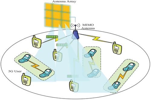
The array consists of just two components. Each antenna in the array is a square patch. The optimal frequency for these antennas is 24 GHz. This precise collection was produced on a Duroid 5880. The permittivity of the substrate, εr, is 2.2 and it’s 0.5 mm thick. Patch antennas have a size of 3.3 mm by 4 mm. When looking at two antennas edge-on, the distance between them is 0.45λo (5.625 mm). They use probes to feed the antennas. Teflon is used in the probe’s coaxial cable (εr = 2.1). The diameters of the inner and outside conductors are 0.6 mm and 2 mm, respectively. 50 is supplied from a strategically chosen feed point Ω the input resistance. The suggested MIMO antenna configuration is shown in .
Figure 1. 5G structure with MIMO antenna.
Outline of EBG
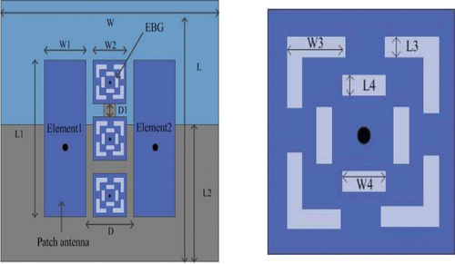
The EBG structure may be thought of as a kind of metamaterial, which refers to a category of materials having properties that are distinct from those of traditional materials. Their interference with electromagnetic radiation at certain frequency ranges may result in the creation of passbands, stopbands, and bandgaps. Bandgaps in EBG may be attributed to both macroscopic and microscopic resonances of periodicity at different scales. A square patch measuring 1.3 by 1.3 millimeters and resembling a mushroom. This patch represents the unit cell size of the EBG architecture used in this study. This square patch, on the other hand, has a slotted ring that measures 0.9 mm in length and 0.12 mm in thickness carved into it, rather than the mushroom-shaped characteristics that are often seen on patches of this kind. As a consequence of this, the EBG may generate a greater capacitance and inductance, which would result in it vibrating at lower frequencies. The engraved slot and the patch are on opposite sides of the via that separates them. The reason for the increase in inductance is that a larger current needs to travel farther. As a consequence of this, the EBG structure may resonate at lower frequencies, which would make it possible to miniaturize it. The diameter of the hole is 0.07 millimeters, while the height is 0.76 millimeters. The substrate is made out of Rogers R04350B, and it has a loss slope of 0.0037 as well as a dielectric value of 3.48.
A critical parametric study of the EBG structure involves analyzing key parameters such as unit cell size, slot dimensions, and spacing between elements. These parameters significantly impact the EBG’s bandgap properties, affecting its ability to suppress mutual coupling. By varying these parameters, researchers can optimize the EBG structure to achieve the desired performance in terms of isolation and bandwidth. Understanding these critical parameters is essential for designing EBG structures tailored to specific antenna array configurations and operating frequencies.
MIMO Antenna with EBG
. depicts the layout of the designed antenna for MIMO structures. The size of the 22 MIMO antenna design are It has a 1 mm thick FR4 substrate as its base. The top side of the planned antenna array has two radiating components in the form of a semicircle with elliptically notched corners. The substrate’s back side is where the ground plane is located. It provides power to each antenna element, a
slimline feed line. How wide is the feeding line
at the antenna’s radiator and rises to
where the SMA plugs in? The feed line’s length is
. There is a breadth of each radiation element
mm cut off abruptly at the top and bottom. Semicircular antenna elements are used to maintain the antenna’s high impedance bandwidth & small size. The distance between the antennas is
and is fine-tuned for enhanced decoupling, etc. Separate ground planes are used for each antenna element. The front edge of the ground plane is rounded by off
and the bottom edge by
. Matching is enhanced at higher frequencies when the top edge is chamfered, and at lower frequencies when the bottom edge is chamfered. depicts the design parameters. The optimized values for each dimension are listed in .
Figure 2. Proposed MIMO model with EBG. (a) MIMO. (b) Structure of EBG.
The functioning of the specific cell of the Electromagnetic Band Gap (EBG) structure is crucial in determining its effectiveness in suppressing mutual coupling between antennas. The unit cell acts as a building block for the entire structure and is designed to exhibit a bandgap, where certain frequencies are forbidden, effectively isolating neighboring antennas. Its performance is characterized by its resonant frequency, the bandwidth of the bandgap, and the amount of attenuation it provides within the bandgap. A well-designed unit cell ensures that the EBG structure effectively reduces mutual coupling, improving the overall performance of the antenna system. The evolution of a unit cell in electromagnetic band gap (EBG) structures involves iteratively refining its geometry using optimization algorithms. This process aims to enhance the EBG structure’s ability to manipulate electromagnetic waves at specific frequencies, improving its performance in terms of isolation and bandwidth. Through iterations, the unit cell evolves to exhibit desired electromagnetic properties, such as creating bandgaps or passbands, crucial for applications like antenna design and signal filtering.
EquationEquation (1)(1)
(1) calculates the resonant frequency of a rectangular patch antenna, considering its length, substrate thickness, and effective permittivity. It indicates the frequency at which the antenna operates most efficiently. EquationEquation (2)
(2)
(2) , derived for the TE10 mode, determines the required length of the patch for resonance at a specific frequency and accounts for the substrate’s influence on the antenna’s electrical properties (Kulkarni J, 2021).
The resonant frequency is given in EquationEquation 1(1)
(1) ,
Where is the resonant frequency, c is the speed of light in free space, L is the length of the patch, h is the substrate thickness, and
is the effective permittivity of the substrate.
EquationEquation 2(2)
(2) represents the Patch length equation for TE10 mode,
Genetic Algorithm for EBG Structure Modeling
Genetic algorithms are a kind of black-box optimization technique that is heavily influenced by evolutionary theory. Although they serve as a useful optimization tool in general, specific implementations of such methods may be based on shaky biological understanding. In this article, we study a completely novel approach: If the genetic operators can be parameterized in a sufficiently broad manner, then may be able to utilize data mining to discover whole new genetic algorithms. To be more specific, model cross- and self-awareness modules for selection and then mutation rate adaptation, respectively, then apply Meta-Black-Box-Optimization to find the best solutions for a variety of issues with optimization. This allows us to find optimal solutions for a variety of optimization challenges. The General Assembly is a strong search strategy that requires microscopic comprehension to successfully execute a search across big search regions or locations where the reason is less recognized. In contrast to traditional search algorithms, which tend to focus their attention on only one area at a time, the GA investigates several different options all at once. In addition to this, it is helpful in the field of non-linear issues, which is infamous for its difficulty. The inherent parallelism of distributed processing machines (in evaluation functions, selects, and other areas) makes it feasible to make use of these machines. It is not difficult to determine which values for the GA parameters should be used to resolve a specific problem. The fact that GA is the most effective method for concurrently optimizing the performance of several various criteria is one conclusion that can be drawn from this.
When building a GA to achieve a certain goal, it is necessary to take into consideration several different possibilities. When choosing an encoding technique, one should base their decision on the particulars of the problem at hand. The sequences of numeric or floating-point data are only two examples of the nonbit-string formats that are now seeing extensive use. Other examples include the formats described in the previous sentence.
The number of potential chromosomes grows exponentially with the scope of the allele set; this is the case, for instance, when the strings are represented by floating-point integers. In many contemporary (or nonclassical) GAs, the set of potential chromosomes is made to closely match the set of potential remedies to the issue by using a variety of representational techniques. After settling on an encoding, a plethora of options opens up. The fitness function, population size, crossover and mutation operators, evolutionary scheme, and stopping/restarting circumstances are all important factors to consider. Experience, problem-specific models, and experimentation with various evolution schemes and other factors make up the conventional design approach. Both provide several instances of nonclassical GAs. Several examples of practical implementations may be found. . shows a possible layout for a classic GA employing conventional genetic operators and full replacement:
Figure 3. GA flowchart.
Create an initial pool of p={
} chromosomes at random.
For every chromosome c within the founding population, determine its fitness, F(c).
Start with a blank successor population and keep repeating until get P chromosomes.
Choose the two chromosomes
To generate offspring with chromosome
To generate d, mutate
To the succeeding population, add c.’
Swap out the original people with the new ones.
Stop the algorithm if a termination condition is satisfied. Else go to Step 2.
Due to their adaptability and resilience, GAs may often be implemented with little effort by simply using industry-standard design options. It may be more challenging to fine-tune this to the level where a specific to the application GA surpasses other current techniques. For situations with many restrictions and outside the scope of standard gradient-based optimization techniques, such as scheduling, GAs have proven extremely beneficial.
Design of MIMI-5 G Networks Using Genetic Algorithm
Designing MIMO-5 G networks using genetic algorithms involves optimizing various parameters to achieve efficient and reliable communication as illustrated in . The GA is used to find the optimal configuration of antennas, transmit power levels, and beamforming strategies to maximize throughput, minimize interference, and improve coverage.
Figure 4. Design steps for MIMI-5G networks using genetic algorithm.
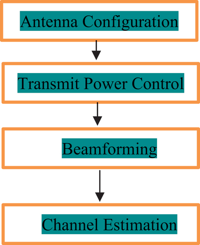
GA can optimize the placement and configuration of antennas in the MIMO array. It can determine the number of antennas, their locations, and orientations to maximize signal coverage and minimize interference. GA can adjust the transmit power levels of each antenna to optimize the signal-to-noise ratio (SNR) and minimize interference with neighboring cells or devices. It can also optimize the power allocation among multiple antennas to improve energy efficiency. GA can optimize the beamforming strategy to focus the transmit power in the direction of the intended receiver, increasing the signal strength and reducing interference. It can also adjust the beamwidth and direction of the beams dynamically to adjust to evolving network circumstances. In order to precisely predict the channel characteristics such as route loss, delay spread, and Doppler shift that are essential for MIMO-5 G communication, GA can optimize the channel estimation process. MIMO-5 G networks can achieve greater data speeds, better coverage, and better overall performance by optimizing these parameters with genetic algorithms. This makes them suited for the rigorous needs of 5 G communication systems.
Design of EBG Decoupling Structure
The proposed MIMO antenna’s EBG construction aids in improving signal separation. The components of the antenna that face each other have been separated by a distance of . As can be seen in the Figures, they are isolated using a parallel configuration of rectangular strips. I (b). In terms of breadth, the outer strips are
. The radii of the circular slots that have been cut into each outer layer are
. The new outer strip’s slotted rectangles measure
. As a result, decoupling at low frequencies is accomplished rather well. Inner strips are 1 mm in width. The distance between these strips of paper is
. There is more than 25” “dB of overall decoupling between the antenna components when the recommended EBG decoupling structure is used. The details of the antenna decoupling structure are shown in .
Table 2. Recommended antenna parameters.
Optimizing the characteristics of an Electromagnetic Band Gap (EBG) structure is necessary to minimize mutual coupling.
This EquationEquation (3)(3)
(3) calculates the reduction in mutual coupling in decibels (dB), where
is the power received when the antennas are uncoupled and
is the power received when they are coupled. The optimized EBG structure aims to maximize this reduction.
The fitness function used in the genetic algorithm can be customized to optimize the EBG structure. It typically includes parameters related to the EBG geometry, such as the dimensions of the unit cell, spacing between elements, and material properties. The fitness function evaluates the performance of each potential EBG design based on its ability to reduce mutual coupling, guiding the genetic algorithm to converge on an optimal solution.
Experimental Results
) illustrate that the suggested design is produced using inexpensive FR4 laminate. The measurements are taken using an Abn N5242A PNA-X network analyzer. displays the measured and simulated impedance matching findings for both symmetric antenna components, demonstrating that an antenna is well-matched in the 3 to 12 GHz frequency range. To further isolate the proposed antenna system, a decoupling structure made up of orbital & and plumb wedged slats is added to the ground’s plane. In Figure, can see how the EBG structure influences the mutual coupling of the radiators. The positioning of the decoupling structure among antenna radiators greatly improves S12/S21, as shown by the results. Isolation using a decoupling device is better over 22 dB in both simulations and measurements.
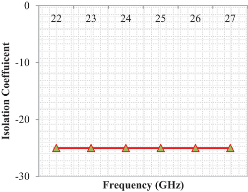
Figure 5. Isolation Co-efficient.
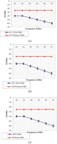
No appreciable change in return loss was seen after including the EBG. provides an analogy of the various antenna parameters.
Table 3. Critical aspects of antenna functionality.
Isolation Coefficient
Parameter S12 is a good proxy for inter-antenna isolation. Without any adjustments, the antenna’s S12 is −24 dB in the frequency center of the band. As can be seen in , when the EBG framework is implemented, S12 drops to around −60 dB.
Radiation Pattern
. illustrates the pattern of radiation that occurs during resonance. The radiation pattern is not significantly hindered by the EBG structure in any way. shows the antenna’s observed radiation patterns in the horizontal and vertical planes corresponding to the three dimensions. This was done to provide a more accurate picture of the performance of the suggested antenna. According to the frequencies of operation that they use, which are 3.48 and 4.88 gigahertz respectively. Calibration is done using the Satimo Star Lab’s machinery, and a 50 ohm load is applied to one meander-line antennas array port to make it functional and the other port inert. As a result of the split EBG construction, the size of the antenna’s rear lobe is shrunk, which is something that can be seen in the radiation pattern. This is completely obvious. Specifically, the band with a frequency of 4.88 GHz. It has been shown that the ratio of the antenna’s front to its rear is 25 decibels. Reducing the rear lobe is another effect of the rectangular EBG Structure’s reflectors function which is responsible for the mutually reinforcing connection that exists between the two sections. This effect contributes to the mutually reinforcing nature of the relationship that exists between the two various components. According to The Repercussions of Antennas, one possible metric to assess how effectively the suggested MIMO antenna handles diversity is the Envelope Correlation Coefficient (ECC). A lower ECC value (one that is below 0.5) is desirable in the majority of situations. The results are shown to fall within a decent range in ) which proves this point. The total active thinking coefficient, often known as TARC, is an additional important performance metric. To have a successful MIMO arrangement, TARC 0 is necessary. The results of the simulation are shown in ). and they show that the recommended dual-port MIMO antenna has a TARC of more than 22 dB over the UWB band spectrum g structure. This value is well within the permitted range for this parameter.
Figure 6. Isolation coefficients.
After incorporating the EBG, there was no discernible difference noticed in the amount of return loss. The different antenna parameters are outlined in , which may be seen below.
Table 4. Critical aspects of antenna functionality.
Correlation Coefficients
The correlation coefficient, often known as the CC, is an essential metric since it represents the degree to which the methods of communication are independent of one another or connected. If want to keep channel capacity high or get a decent performance from diversity, should try to keep the value of CC as low as possible for MIMO antennas. In situations in which there is isotropic or uniform signal transmission, the envelope correlation coefficient (ECC) is used. and correlation coefficient (CC)
may be computed by the use of the S-parameters. The meaning of this statement may be found in below EquationEquation (4)
(4)
(4) ,
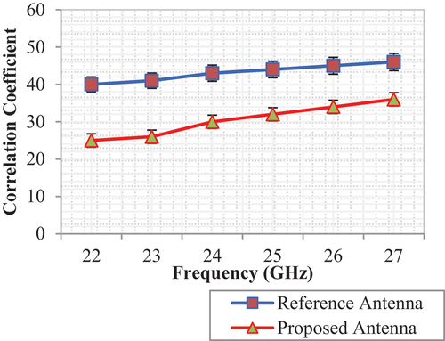
where is the difference in S-parameter value between the ith and jth elements of the antenna. . illustrates the calculated correlation coefficient of the antennas that were developed. The antennas’ correlation coefficients with the rectangle EBG Structure are 0.013 and 0.001, in that order, when it comes to the frequency range in which the dual-band operating system is active. . shows that there is more association between the proposed antenna and the 3.7–3.8 GHz band, which could be related to the limits of the split EBG design.
Figure 7. Simulated radiation pattern for with and without EBG structure (a). 22GHz, (b). 23GHz, (c). 24GHz, (d). 25GHz, (e). 26GHz, and (f). 27GHz.
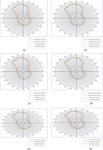
Figure 8. Correlation coefficient vs. Frequency.
Because of the S-parameters, the equation for lossy antennas is not correct, regardless of how high the degree of isolation is; instead, the radiation pattern formulation is the one that should be used, as is shown in the following equation (5).
where or 2
is the antenna’s area radiation waveform. The antenna’s value for correlation with the rectangular EBG Topology in the dual-band operating band is 0.089 and 0.043, respectively. MATLAB is used to calculate the planned antenna’s correlation coefficient.
The outcomes of the experiments show that the suggested MIMO antenna design, integrated with an EBG structure, effectively enhances signal isolation and maintains antenna performance. The impedance matching results show good performance across the 3 to 12 GHz frequency range. The EBG structure significantly improves isolation between antennas, with decoupling exceeding 25 dB in simulations and measurements. Radiation patterns remain largely unaffected by the EBG, indicating that its inclusion does not hinder antenna performance. Good MIMO antenna diversity and performance are shown by the envelope correlation coefficient (ECC) and total active reflection coefficient (TARC) values falling within the acceptable ranges. The correlation coefficients demonstrate that, particularly in the dual-band operating frequency spectrum, the suggested antenna design maintains a low correlation between antennas, which is essential for preserving good channel capacity and diversity performance.
Conclusion
The rectangular Electromagnetic Band Gap (EBG) Structure has proven effective in reducing mutual coupling and enhancing The ratio of meander-line MIMO antennae’ front to rear ends. Experimental results demonstrated a remarkable decrease in mutual coupling, with noise reduction reaching as high as −60 dB in the frequency range of interest, when the rectangular EBG Structure was placed between the antennas. When compared to the reference antenna, this arrangement greatly enhanced isolation, with a front-to-back ratio of 25 dB at 4.88 GHz. Further reductions in mutual coupling between dual-band microstrip antennas can be accomplished by varying the length of the L-shaped bridge of the EBG unit cell and the number of splits on the EBG surface. The suggested EBG Structure’s matching and gain performance for a dual-band antenna array is the subject of ongoing research. The novel EBG framework constructed for this study successfully reduced interference between different patches, resulting in a significant decrease in mutual coupling by around 30 decibels. This improvement in isolation and performance validates the effectiveness of the proposed MIMO antenna design integrated with the EBG structure. The radiation pattern remained consistent across different frequencies, indicating that the EBG structure does not compromise the antenna’s radiation characteristics. Overall, the use of the rectangular EBG Structure offers a promising solution for improving the performance of MIMO antennas, particularly in terms of reducing mutual coupling and enhancing isolation.
Ethics approval and consent to participate
No participation of humans takes place in this implementation process.
Human and animal rights
No violation of Human and Animal Rights is involved.
Acknowledgements
There is no acknowledgement involved in this work.
Disclosure statement
No potential conflict of interest was reported by the author(s).
Data availability statement
Data sharing not applicable to this article as no datasets were generated or analyzed during the current study.
Correction Statement
This article has been republished with minor changes. These changes do not impact the academic content of the article.
Additional information
Funding
References
- Alharbi, A. G., J. Kulkarni, A. Desai, C. Y. D. Sim, and A. Poddar. 2022. A multi-slot two-antenna MIMO with high isolation for sub-6 GHz 5G/IEEE802. 11ac/ax/C-band/X-band wireless and satellite applications. Electronics 11 (3):473. doi:10.3390/electronics11030473.
- Ashok Babu, P., L. Kavisankar, J. Xavier, V. Senthilkumar, G. Kumar, T. Kavitha, and A. G. Adigo, G. Harikrishnan, A. Rajaram, A. G. Adigo. 2022. Selfish node detection for effective data transmission using modified incentive sorted pathway selection in wireless sensor networks. Wireless Communications and Mobile Computing 2022:1–23. doi:10.1155/2022/9359135.
- Beigi, P., M. Rezvani, Y. Zehforoosh, J. Nourinia, and B. Heydarpanah. 2020. A tiny EBG‐based structure multiband MIMO antenna with high isolation for LTE/WLAN and C/X bands applications. International Journal of RF and Microwave Computer‐Aided Engineering 30 (3). doi:10.1002/mmce.22104.
- Famoriji, O. J., O. Y. Ogundepo, and X. Qi. 2020. An intelligent deep learning-based direction-of-arrival estimation scheme using spherical antenna array with unknown mutual coupling. IEEE Access 8:179259–71. doi:10.1109/ACCESS.2020.3027623.
- Fritz‐Andrade, E., Á. Pérez-Miguel, R. Gómez-Villanueva, and H. Jardón-Aguilar. 2020. “Characteristic mode analysis applied to reduce the mutual coupling of a four‐element patch MIMO antenna using a defected ground structure”. IET Microwaves, Antennas & Propagation. doi:10.1049/iet-map.2019.0570.
- Ghosh, J., and D. Mitra. 2020. “A technique for reduction of mutual coupling by steering surface wave propagation. Microwave and Optical Technology Letters 62:1957–63. doi:10.1002/mop.32278.
- Guo, C., Z. Zhang, X. Fu, and J. Wang. 2023. A frequency-reconfigurable antenna with filtering characteristics using characteristic mode analysis. IEEE Antennas & Wireless Propagation Letters 22 (8):102679–88. doi:10.1109/LAWP.2023.3264666.
- Khajeh‐Khalili, F., M. A. Honarvar, M. Naser‐Moghadasi, and M. Dolatshahi. 2020. Gain enhancement and mutual coupling reduction of multiple‐intput multiple‐output antenna for millimeter‐wave applications using two types of novel metamaterial structures. International Journal of RF and Microwave Computer‐Aided Engineering 30 (1). doi:10.1002/mmce.22006.
- Khan, M. S., S. Khan, O. Khan, S. Aqeel, N. Gohar, and M. Dalarsson. 2023. Mutual coupling reduction in MIMO DRA through metamaterials. Sensors 23 (18):7720. doi:10.3390/s23187720.
- Kulkarni, J., A. Desai, and C. Y. D. Sim. 2021. Wideband four-port MIMO antenna array with high isolation for future wireless systems. AEU-International Journal of Electronics and Communications 128:153507. doi:10.1016/j.aeue.2020.153507.
- Kulkarni, J., R. K. Gangwar, J. Anguera, and J. Anguera. 2022. Broadband and compact circularly polarized MIMO antenna with concentric rings and oval slots for 5G application. IEEE Access 10:29925–36. doi:10.1109/ACCESS.2022.3157914.
- Li, Y., L. A. Bian, Y. Chen, Y. Liu, R. Wang, S. Xie, and S. Xie. 2023. Mutual coupling reduction for monopole MIMO antenna using l-shaped stubs, defective ground and chip resistors. AEU-International Journal of Electronics and Communications 160:154524. doi:10.1016/j.aeue.2022.154524.
- Maimouni, M., B. Abou El Majd, and M. Bouya. 2022. RFID network planning using a new hybrid ANNs-based approach. Connection Science 34 (1):2265–90. doi:10.1080/09540091.2022.2115011.
- Mandal, S., and C. K. Ghosh. 2021. Low mutual coupling of microstrip antenna array integrated with dollar shaped resonator. Wireless Personal Communications 119:777–89. doi:10.1007/s11277-021-08237-1.
- Tran, V., T. K. Dhasarathan, J. Garner, B. A. Kulkarni, Y. Li, and Y. Li. 2023. Mutual coupling reduction in dual-band MIMO antenna using parasitic dollar-shaped structure for modern wireless communication. IEEE Access 11:5617–28. doi:10.1109/ACCESS.2023.3235761.
- Verma, A., R. K. Arya, R. Bhattacharya, and S. N. Raghava. 2023. Compact PIFA antenna with high gain and low SAR using AMC for WLAN/C-band/5G applications. IETE Journal of Research 69 (7):4422–32. doi:10.1080/03772063.2021.1945958.
- Yuan, S. S., X. Chen, C. Huang, and E. I. Wei. 2023. Effects of mutual coupling on degree of freedom and antenna efficiency in holographic MIMO communications. IEEE Open Journal of Antennas and Propagation 4:237–44. doi:10.1109/OJAP.2023.3245667.