
 ?Mathematical formulae have been encoded as MathML and are displayed in this HTML version using MathJax in order to improve their display. Uncheck the box to turn MathJax off. This feature requires Javascript. Click on a formula to zoom.
ABSTRACT
This paper thoroughly reviews the influence of protuberances on the performance of a wind-turbine blade in terms of aerodynamic characteristics, power generation capability, and noise emission. It is observed that the protuberances are significantly useful in improving the aerodynamic performance of wind turbine blades, especially in the post-stall regime and during fluctuating wind conditions, such as wind gusts. The protuberance amplitude was found to be the dominant parameter to influence the blade performance. The amplitude and wavelength were tested in the range of 2–12%c and 2–50%c, respectively. The highest wind turbine performance was observed at small amplitude and large wavelength in the pre-stall regime and at large amplitude and small wavelength in the post-stall regime. Incorporating leading edge protuberances may increase lift and power coefficients by 50 and 55%, respectively, and reduce noise emission by nearly 16 dB. With the increase in the angle of attack, the instability noise was found to change its form. The broadband noise forms at a lower angle of attack (~2°) which converts to the tonal noise at the angle of attack, 6.5°. The protuberances substantially alter the boundary layer flow, subsequently modifying the pressure and velocity field over the suction surface of the blade. A pair of vortices forms across a protuberance, which exchanges momentum with the boundary layer flow and helps delay/eliminate the flow separation. This flow separation control is responsible for the benefits as mentioned above.
Introduction
To fulfill the growing demand for energy, researchers across the world are focusing on renewable energy sources. Wind energy is a popular and widely used form of the renewable energy methods. The rotor blade is the most essential element of the wind turbines, which extracts the wind energy and converts it into mechanical and, subsequently electrical energy. The aerodynamics of the rotor blade significantly affects the wind turbine performance. At low Reynolds number, the flow may separate from the blade surface leading to the loss of lift and substantial increase in drag force. This severely deteriorates the power generation of the wind turbine system. The passive and active flow control methods may be employed to mitigate the undesirable effects of the flow separation. The former method involves the dimples (Sedighi, Akbarzadeh, and Salavatipour Citation2020), serrations (Llorente and Ragni Citation2020), vortex generators (Lin Citation2002), leading edge protuberances (LEPs) (Bapat, Salunkhe, and Varpe Citation2021) etc. In contrast, the active flow control method uses vortex generating jets (Salunkhe and Pradeep Citation2010), suction (Rezaeiha, Montazeri, and Blocken Citation2019), synthetic jets (Salunkhe et al. Citation2016), plasma actuators (Xu et al. Citation2022), etc. These methods have been used in several applications, including wings, compressors, turbine blades, etc. Few researchers have used the micro-cylinders at the leading edge of the blade to improve the wind turbine performance (Zhong, Li, and Guo Citation2017) Research is also being carried out using newer materials such as carbon fiber (Veers et al. Citation2003).
Xie et al. (Citation2017) demonstrated the concept of a vertically staggered arrangement, wherein, twenty small vertical axis wind turbines (VAWTs) are placed around the large horizontal axis wind-turbines (HAWTs). It was reported that this arrangement not only help increase the power production by 32% but also increases the power production of individual HAWTs by 10% because of the turbulent flow caused by smaller HAWTs. Zhong, Li, and Guo (Citation2017) placed a cylindrical rod in front of the S809 aerofoil and observed a 30.7% enhancement in lift-to-drag ratio and delay in stall angle.
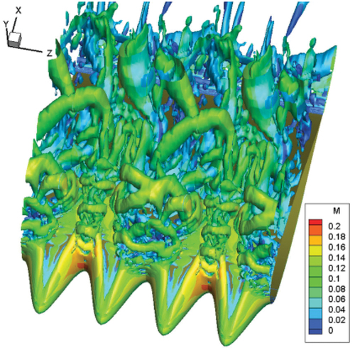
Protuberances, also commonly termed as tubercles, are the geometric modifications over the leading and/or trailing edge of the blade. It was discovered that these tubercles are naturally present on Humpback Whale flippers, which enhances the lift coefficient and reduces the drag coefficient even at higher angles of attack (Fish and Battle Citation1995). Enormous research has been performed on using protuberances in marine applications (Wei, New, and Cui Citation2015). The protuberances positively alter the pressure and velocity field over the wind turbine blades. The flow passing over the protuberances forms a pair of counter-rotating vortices, as shown in . The interaction of these vortices with the boundary layer flow energizes it, and alleviate the severity of adverse pressure gradient. This may inhibit the onset of the stall inception.
Figure 1. Representation of flow structures over an airfoil with leading edge protuberances (Zhao, Zhang, and Xu Citation2017).
The wind turbine performance is significantly affected by the LEPs in terms of aerodynamic characteristics, power coefficient, nature of stall inception, noise emission, among others. According to the authors, this is the first-ever attempt to report the influence of protuberances on the above-mentioned parameters at different wind speeds and conditions. Past research has investigated these parameters individually at a specific configuration. Also, the past literature falls short of adequately addressing the influence of protuberances on noise emission, which is covered here in detail. A few studies have shown contradictory findings, particularly regarding the impact of the wavelength and amplitude of protuberances on blade performance. The current study provides a more in-depth understanding of this aspect. The present study may help provide essential guidelines for an efficient design of wind turbine blades with LEPs.
Review Methodology
The present review revolves around the key parameters that influence the protuberance-based wind turbine performance. The refereed journal articles and peer-reviewed conference papers were collected to investigate the effect of LEPs on the wind-turbine performance through experimental, numerical, and theoretical approaches. Most of these papers were from the last decade. Though, the current work considers both leading and trailing edge protuberances, seldom research has been conducted on the latter. Hence, this work primarily focuses on the leading edge protuberances. Also, it considers both, horizontal and vertical axis wind turbines for the analysis of blades with protuberances. The influence of LEPs on wind turbine performance in extreme conditions, such as, high winds, strong gusts, icy conditions etc. is not considered in the present work.
This paper is organized as follows: The protuberance nomenclature is provided in section 3. Section 4 explains the mechanism of stall inception after the inclusion of protuberances. The amplitude and wavelength are the critical geometric parameters of the protuberances. Their effect on the blade performance is covered in section 5. The impact of protuberances on the power generation capacity of a wind turbine is explained in section 6. Section 7 highlights the change in aerodynamic characteristics over the blade due to the incorporation of protuberances. The role of protuberances in noise suppression is discussed in detail in section 8. The conclusions and the scope for future research are described in section 9.
Nomenclature of protuberances
The wavelength and amplitude specify a protuberance. A wind turbine blade may have single, intermittent, or continuous protuberances, as shown in .
Figure 2. A wind turbine blade with (a) single, (b) intermittent, and (c) continuous protuberances.
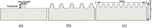
In a single protuberanced blade, the protuberance is usually located at the center of the blade span. A blade with intermittent protuberances has fewer protuberances with equal spacing between the successive protuberances. The continuous protuberances include the continuous distribution of protuberances over the whole span of the blade, as shown in . Apart from the number of protuberances, they can also be classified based on their shape, such as sinusoidal, saw-tooth, square-shaped, etc. The sinusoidal protuberances have been commonly used in the past literature due to their simplicity and better performance.
The protuberances significantly affect the flow-field and different wind turbine blade performance parameters. The following sections discusses about this in a greater depth.
Effect of protuberance on the stall inception characteristics
The onset of stall inception adversely affects the blade performance. It increases the drag coefficient and reduces the lift coefficient, significantly affecting a wind turbine’s power generation capacity. The delay/elimination of stall inception substantially improves the wind turbine performance. Watts and Fish (Citation2001) reported a close relationship among the shear stress, pressure gradient and the stall inception. The addition of protuberances reduces the intensity of the adverse pressure gradient, leading to decreased boundary layer thickness, increased shear stress and hence improved resistance to the stall inception. Miklosovic et al. (Citation2004) performed experimental studies on a scaled model of Whale flippers and revealed a 40% delay in stall angle and over 4.8% rise in lift coefficient in the post-stall condition. The improved lift and drag characteristics due to the scalloped leading edge act like a substitute to tab-type vortex generators. Hrynuk and Bohl (Citation2020) analyzed the vortex behavior for the blade without and with LEPs. The formation and separation of the vortex were different for both cases. The dynamic stall vortex was stronger for the blade with LEPs and remained close to the blade surface. It was reported that under fluctuating wind conditions the turbine blade with protuberances performs better than that of without protuberances.
Huang et al. (Citation2015) stated that the LEPs effectively delay the stall inception of small-scale HAWT at lower rotor speeds. However, the protuberances are not favorable at higher rotor speeds. Cai et al. (Citation2018) demonstrated that in turbulent flow conditions, the LEPs act as the vortex generators, whereas, in the case of laminar flow, the protuberances have a mild effect on performance improvement. In subsequent studies, Cai et al. (Citation2017) incorporated the protuberances and observed that the flow separation is periodic and symmetric below a certain angle of attack (AoA). Beyond the threshold AoA, the flow was observed to be aperiodic and asymmetric, making it challenging to predict the flow characteristics. Wang, Hu, and Zhang (Citation2015) deployed LEPs on a bio-inspired wing and observed the smooth stall characteristics. The initial studies reported a reduction in lift and an increase in drag. However, these characteristics were later improved with an increase in the angle of attack. Asli, Mashhadi Gholamali, and Mesgarpour Tousi (Citation2015) performed numerical studies on the S809 blade and reported that the protuberances form vortices that help retain the attached boundary layer flow and prevent flow separation. The protuberances were found to reduce the lift coefficient at lower AoA. However, at higher AoA, the presence of protuberances help prevent the deep stall condition. Abate, Mavris, and Sankar (Citation2019) simulated flow characteristics over an NREL Phase IV wind turbine with protuberances. Substantial performance improvement was observed near the wind speed of 20 m/s. On the contrary, the performance was found to deteriorate at a wind speed of 10 m/s. At this speed, the wind-turbine operation was limited by the onset of the stall inception. It was noted that for the blades with LEPs, the generation of counter-rotating vortices blocks the spanwise flow and reduces the resistance to the stall inception. This is in contrast with the observations of Zhao, Zhao, and Liu (Citation2020a) and Zhong, Li, and Guo (Citation2017) who reported that the vortices produced by the leading edge protuberances help impart the much-needed momentum and thereby improve the aerodynamic performance of the blade.
da Silva Abrantes et al. (Citation2017) investigated the influence of LEPs on the finite and infinite wings to unravel the influence of two- and three-dimensional flows. Though, both wings showed smooth stall characteristics, the infinite wing deteriorated the aerodynamic performance of the wing. Sedney (Citation1973) as well carried out similar studies and reported that protuberances had negligible influence in the two-dimensional case, however, in three-dimensional case, the protuberances help form the vortex structures, which subsequently improves the aerodynamic performance. Miklosovic, Murray, and Howle (Citation2007) reported that three-dimensional effects are mild in the pre-stall regime. In this regime, a decrease in the lift coefficient and an increase in the drag coefficient were observed. The opposite trend was reported in the post-stall regime. The use of protuberances was beneficial for power generation, especially at low and unsteady wind speeds.
Arunvinthan, Pillai, and Cao (Citation2020) reported that the protuberances help improve the lift coefficient and decrease the flow separation tendency at higher AoA. The experimental studies were performed on small, medium and high LEPs of a wind turbine blade. The abrupt type stall inception was transformed into the progressive type after incorporating the medium and high LEPs. The small LEP was found to have negligible influence on the stall characteristics of the blade. Sudhakar, Karthikeyan, and Venkatakrishnan (Citation2017) investigated the effect of tubercles on blade performance and reported that the addition of tubercles improved the stability of the system and eliminated the hysteresis in the pitching moment. This performance improvement substantially helps during the sudden vertical gusts. Shi, Atlar, and Norman (Citation2017) used the Stereo Particle Image Velocimetry technique and showed that the presence of tubercles weakens the tip leakage vortex, leading to a substantial reduction in the axial trajectory. The overall impact of this phenomenon is to reduce the three-dimensional effects. The turbine blade with tubercles maintained the attached flow even at higher angles of attack.
Kumar and Shah (Citation2017) reviewed the research work on HAWT blades with protuberances and reported that the application of protuberances suits best for thick blades with a taper and sweep planform. Zverkov et al. (Zverkov, Zanin, and Kozlov Citation2008) unraveled the mechanism of boundary layer modification due to the LEPs. The boundary layer flow separates at the groove of the protuberance and remains attached to the hump. This three-dimensional boundary layer structure offers increased resistance for the flow separation, resulting in higher lift coefficient and delayed stall inception. Swanson and Isaac (Citation2011) found that for a straight wind-turbine blade, the vortices rotate in the same direction, merge, and form a strong tip vortex. This leads to an increase in induced drag. In contrast, for a blade with LEPs, the vortices rotate in the opposite direction, cancel each other and substantially reduce the strength of the tip vortex, leading to the enhanced blade performance.
Zhang, Zhang, and Cai (Citation2019) demonstrated that after incorporating the LEPs, the blade performance was improved, especially in the post-stall regime. The protuberances also enhanced the serviceable lifetime of the blades. Subsequently, Zhang et al. (Citation2020) reported the effect of LEPs on the aerodynamic performance of a wind-turbine blade during the dynamic stall. The results showed that hysteresis in aerodynamic loads can be significantly decreased and the symptoms of the dynamic stall under reduced frequencies can also be suppressed by incorporating the LEPs. The influence of protuberances on stall inception phenomena is tabulated in . In this table, the nomenclature is, S – small, M – medium, L – large, A – amplitude, λ – wavelength and c – chord. At a couple of places, the blades with LEPs showed early stall inception compared to the smooth blade case. The flow separation initiated at the troughs of the blunt leading edge, and it is attributed to the large radius of curvature of the protuberance.
Table 1. Effect of protuberances on the stall inception phenomena.
Skillen et al. (Citation2015) numerically demonstrated that the LEPs cause the formation of secondary flow due to the spanwise pressure gradient. The entrainment of high momentum fluid in the low momentum region resulted in substantial delay in stall inception and improvement in lift coefficient. Similarly, Serson, Meneghini, and Sherwin (Citation2017) explained the flow control mechanism for a wing with LEPs at a low Re number of 1000. It was reported that the LEPs deform the wing and forms the pressure gradient. At low Re no, the lift-to-drag ratio was reduced. The flow was attached downstream of the peaks, whereas, the separated flow was observed downstream of the troughs. Hansen et al. (Citation2016) reported that due to the particular shape of protuberances, a strong pressure gradient forms near the blade’s leading edge, which subsequently causes the formation of a vortex pair. The interaction of this vortex pair with the boundary layer flow delays the flow separation. The performance of airfoil with protuberances was slightly better than that of without the protuberances.
Zhao, Zhao, and Liu (Citation2020b) conducted the dynamic mode decomposition analysis based on the numerical simulations. The working mechanism of the LEPs was observed as the momentum exchange from the troughs to the neighboring peaks through the formation of strong streamwise vortices. Subsequently, Zhang, Wang, and Xu (Citation2014) also reported that the LEPs induce strong streamwise vortices, which help improve the much-needed momentum to delay the flow separation. This flow control mechanism was reported by other researchers as well (Yasuda et al. Citation2019). Zhang et al. (Citation2022) demonstrated that the LEPs split the large scale shedding vortices into multiple small-scale ones, thereby reducing their strength, and helping bring stable flow conditions over the blade surface. This phenomenon not only improves the aerodynamic performance of the wind turbine but also substantially reduces the noise. In subsequent studies, Zhang, Cao, and Zhang (Citation2021) investigated the effect of LEPs on the thick airfoil of a wind turbine blade. The thick airfoil with LEPs of small amplitudes and short wavelengths was found to significantly improve the flow separation control capability. The stall inception process was found to be very smooth and gentle. The fluctuations in the aerodynamic coefficients were substantially reduced for the thick airfoil.
Roy, Das, and Biswas (Citation2023b) studied the effect of spherical and triangular shapes of the leading edge protuberances on the stall characteristics of a wind turbine blade, NACA 4415. The early flow separation was observed at 0.2c for the blade without LEPs whereas, for spherical and triangular LEPs, the flow separation was extended to 0.7c and 0.54c, respectively. At higher AoA (), the spherical LEP led a higher lift coefficient than the triangular LEP. Pérez-Torró and Kim (Citation2017) numerically investigated the deep stalled airfoil, NACA 0021, with sinusoidal LEPs. The low-pressure spots were observed at the trough of the LEPs, which subsequently transformed into the laminar separation bubbles. The formation of these bubbles was not observed at each trough.
Yan et al. (Citation2021) reported that after incorporating the LEPs, the leading edge stall was transformed into the trailing edge stall with a substantial increase in wall shear stress. An increase in wall shear stress indicates higher frictional effects between the flow and the protuberance blade suction surface, which leads to a weak dynamic stall. Huang et al. (Citation2016) observed that the stalling phenomenon was improved at low-speed conditions, however, beyond a critical tip speed ratio, the wind turbine performance was mildly deteriorated. Joseph and Sathyabhama (Joseph and Sathyabhama Citation2022) observed the premature stall inception from 20 to 14° after incorporation of the LEPs. The LEPs transformed the deep stall into the progressive stall for all Re nos. The stall was initiated at the midspan for the baseline case, which progressed toward the tip region after increasing the AoA. This stall progression toward the tip was absent for the blades with LEPs. Guerreiro and Sousa (Citation2012) also reported the transformation of the abrupt stall into a smooth stall after incorporating the leading edge protuberances. The hysteresis was also eliminated due to the LEPs. The LEPs were beneficial, especially at lower AoA.
Ng, New, and Palacios (Citation2017) conducted studies on NREL blades by placing the protuberances in three ways. 20–95% span, near blade root 20–40%, and near blade tip 75–95%. The former configuration reduced root bending moment and torsional loads by 6% and 17%, respectively. The protuberances near the blade root were useful in preventing the stall inception due to the low wind speed. The protuberances at the wing tip help avoid stalling that may have been caused due to the large tip deflections.
Effect of protuberance wavelength and amplitude on the blade performance
The wavelength and amplitude of a protuberance significantly affect the blade performance. Numerous studies have been conducted by varying the amplitude and wavelength of protuberances to assess their effect on blade performance improvement.
Johari et al. (Citation2007) reported that the protuberance amplitude has a significant influence on the blade performance than the wavelength. Below the stall angle of the baseline case, the airfoil with LEPs increased the drag and reduced the lift. The largest amplitude resulted in almost a constant lift coefficient in the AoA range, 10 to 26°. Van Nierop, Alben, and Brenner (Citation2008) also observed that the protuberance amplitude is a dominant parameter over the wavelength in deciding the wind turbine performance. In contrast, Guerreiro and Sousa (Citation2012) found that both amplitude and wavelength significantly influences the wind turbine blade performance. Hansen, Kelso, and Dally (Citation2011) performed experiments on NACA 65–021 and NACA 0021 using different combinations of protuberance amplitudes and wavelengths. In the pre-stall regime, the smaller amplitude and shorter wavelength resulted in improved blade performance in terms of lift coefficient and stall angle. However, the increased amplitude and reduced wavelength improved the blade performance in the post-stall regime. There is a critical limit for the wavelength beyond which the blade performance deteriorates.
Zhang and Wu (Citation2011) numerically demonstrated that the 60% region to the blade tip is the major region of a wind-turbine blade where the protuberances are crucial in enhancing the blade performance. The increase in wavelength and amplitude in this region enhanced the wind-turbine’s power output. It was also reported that the LEPs are helpful during the off-design conditions since they causes early flow separation during the design condition due to the uneven shape at the leading edge. Subsequently, Ke et al. (Citation2022) recommended a smaller amplitude-to-wavelength ratio with the placement of protuberances over 60% of the blade span at low speeds and a higher amplitude-to-wavelength ratio with the placement of protuberances over 23% of the blade span at high-speed conditions for a HAWT blade. The protuberances deteriorate the wind turbine performance at wind speeds lower than 7 m/s and improve the same at higher speeds. Favier et al (Favier, Pinelli, and Piomelli Citation2012) varied the amplitude and wavelength of protuberances on NACA 0020 wing in deep stall condition at 20°. The improved performance was observed at a particular configuration: amplitude of 7%c and wavelength of 1c. At this configuration, the strong streamwise vortices were generated, which helped partially reattach the boundary layer flow. Ni, Su, and Dhanak (Citation2018) conducted experimental studies on twisted and untwisted aerofoils (NACA 0021) with and without LEPs. The twisted airfoil with LEPs of large amplitude was found to improve the post-stall performance. For smaller protuberance amplitudes, the stall cells were found to merge to become a large stall cell, which deteriorated the blade performance.
Paula (Citation2016) investigated the effect of airfoil thickness and different combinations of protuberance amplitudes and wavelengths on NACA0012, NACA0020 and NACA0030 airfoils. The Re was varied from 50,000 to 2,90,000. The lift coefficient was always higher than the smooth blade case for any combination of airfoil thickness and protuberance configuration. It was also reported that the thin airfoil with low Re no. improved the blade performance amongst the other cases studied. Thangarajan and Velamurali (Wei et al. Citation2019) demonstrated that small amplitude and short wavelength substantially improve the lift-to-drag ratio. A large amplitude resulted in a gentle stall and small wavelength enhanced the maximum lift.
Huang et al. (Citation2016) optimized the wind turbine blades with LEPs under low rotational speeds. The blade span was found to be the most influencing parameter, whereas the wave-amplitude had the least effect on the performance improvement of the blades. Yan et al. (Citation2021) varied the amplitude and wavelength of a VAWT blade and reported that the LEP amplitude significantly influences the blade performance than the wavelength. The best performance was observed at 1%c amplitude and 2.5%c wavelength. Seyhan et al. (Citation2022) performed experimental studies on non-uniform LEPs of a tapered swept-back airfoil. Three geometries were suggested viz., T1 (constant amplitude a1 and wavelength λ1), T2 (constant amplitude a2 and wavelength λ2) and T3 (sum of two sine waves with amplitudes a1 and a2 and wavelengths λ1 and λ2). Among the three models, model T3 resulted in the best performance in terms of a 31.4% increase in lift coefficient, 33.2% reduction in drag coefficient and 96. 8% enhancement in lift-to-drag ratio at an AoA, 2° and Re no of 5.5 × 10⁴. At lower Re no, the model T1 led the highest lift coefficient of 60.1%. Roy, Das, and Biswas (Citation2023a) presented a thorough review of the application of tubercles in wind turbine blades. It was reported that in low wind speed conditions, the small amplitude and small wavelength improve the aerodynamic characteristics, whereas at high wind speeds, the use of large amplitude and large wavelengths is beneficial for the aerodynamic performance of the blades. The incorporation of protuberances ensures the generation of high torque and power even at low tip speed ratios. Subsequently, Syed et al. (Ul Hassan et al. Citation2023) reported that at design condition, the large wavelength and small amplitude improved the wind turbine performance. In contrast, at off-design condition the small wavelength and large amplitude was beneficial. The tubercle amplitude was found to have a significant influence on the wind turbine performance than the wavelength. Aftab et al. (Citation2016) also reported that the LEP amplitude significantly influences the blade performance compared to the wavelength.
Zadorozhna et al. (Citation2021) recommended the use of spherical tubercles at low Re no. The tubercle amplitude was varied to 0.005c, 0.01c and 0.03c. The small amplitude tubercles were found to perform better among others for the AoA range of 0–4°. The performance enhancement due to the tubercles is attributed to the favorable pressure distribution over the suction surface, which thickens the laminar boundary layer. The thick boundary layer offers lower skin friction drag and hence improved aerodynamic performance. Reddy and Sathyabhama (Citation2023) tested the protuberances of sinusoidal, triangular, and slotted geometries with different amplitudes of 0.03c, 0.06c, and 0.11c and wavelengths of 0.11c, 0.21c, and 0.43c. The performance of triangular and slotted geometry was the best compared to sinusoidal geometry. Regarding stall delay and post-stall performance, the slotted geometry performed the best. This was attributed to the alteration in the pressure field over the suction surface of the blade due to the modification of the blade leading edge.
Effect of protuberance on the power coefficient
The blade design is crucial as it significantly influences the power generation from a wind-turbine system. The power generation capability closely relates to the aerodynamic characteristics over the blade surface.
Lin et al. (Citation2016) performed numerical simulations on an H-type Darrieus rotor with trailing edge protuberances on the blades. The incorporation of trailing edge protuberances improved the maximum thrust from .38 to 2.31%. The power coefficient was enhanced by a maximum 16.4% after increasing the protuberance amplitude and wavelength. The protuberances on the trailing edge produce vortices that shift toward the leading edge by turning the blades by azimuth angles from 90° to 270°. This leads to an increase in thrust due to the low-pressure zone formed along the leading edge. Bai, Wang, and Chen (Citation2016) observed that the blades with sinusoidal protuberances having larger wavelength result in higher power coefficient at a tip speed ratio (TSR) lower than 3. However, the blades with short wavelengths performed better at a higher tip speed ratio. The power coefficient was improved when the blades moved with a high angle of attack. It was recommended to use the protuberanced blades with large amplitude and large wavelength for higher wind speed operations. Kunya et al. (Citation2019) performed the feasibility study of implementing the wind turbines in Nigeria, where the typical wind speed is usually lower. The incorporation of sinusoidal leading edge protuberances improved the power coefficient from .237 to .303 at a tip-speed ratio of 6. Rinehart et al. (Citation2014) numerically investigated the effect of tubercles on the power and thrust of a wind turbine blade at different speeds of 6, 11.3, and 15 m/s. The tubercles were found to have a mild effect on the blade performance. For all speeds, the presence of tubercles marginally decreased the power generation rate from 2.186 to 2.17, 13.63 to 13.58 and 12.85 to 12.78 MW at 6, 11.3 and 15 m/s wind speeds, respectively.
Lin and Chiu (Citation2020) performed experimental studies on a 25 kW HAWT blade, fx63, with leading edge protuberances. At a 5° pitch angle, the average enhancement in wind turbine output efficiency and the tip speed ratio were 17.7 and 13.4%, respectively. At the starting wind speed of 4 m/s, the incorporation of LEPs doubled the wind turbine power output from 786.5 W to 1.5 kW. The incorporation of protuberances was found to reduce the output power fluctuations substantially. Gonçalves, Pereira, and Sousa (Citation2022) reported that after using the leading edge protuberances, the enhancement in power coefficient was in the range of 46–20% for the wind speed range of 5.5–9 m/s. The tip-speed ratio was found to be unaffected. The minimum wind speed at which the wind turbine stops to operate was reduced from 7 to 5.5 m/s after incorporating the leading edge protuberances. Yan et al. (Citation2021) observed the substantial influence of leading-edge protuberances on the blade performance for a tip speed ratio smaller than 3. Above this speed, the power performance was observed to be unaffected. The power coefficient was increased by 15.3%. Syed et al. (Ul Hassan et al. Citation2023) conducted numerical simulations on a tubercled blade of a VAWT. The power performance of wind turbine was found to be degraded at design conditions and substantially improved at off-design conditions. Thus, for VAWT, the tubercles were beneficial only in off-design conditions. Roy, Das, and Biswas (Citation2023b) investigated the effect of spherical and triangular protuberances and observed that the spherical LEPs improved power coefficient by 8.2% over the triangular protuberances. Sridhar, Joseph, and Radhakrishnan (Citation2022) performed computational studies on a VAWT blade with four types of tubercles. The improvement in power coefficient deteriorated below the tubercle wavelength of 1.5. The power coefficient was a strong function of the tubercle wavelength rather than the amplitude. The small amplitude and large wavelength significantly improved the blade efficiency over the entire range of the tip-speed ratio. The best configuration improved the power coefficient by 28%, increased the lift coefficient by 14% and reduced the drag coefficient by 28%.
Effect of protuberance on the aerodynamic characteristics of flow
The shape of an airfoil significantly affects the aerodynamic characteristics of the flow flowing over it. With the incorporation of protuberances, the modified shape of the wind turbine blade alters the aerodynamic characteristics of the flow. In this section, the modification in aerodynamic characteristics of the flow due to the protuberances will be discussed in detail.
Zhang, Wang, and Xu (Citation2013) performed experiments over NACA634-021 aerofoil at an angle of attack ranging between 16–70°. The incorporation of LEPs enhanced the lift coefficient and the lift-to-drag ratio by 25% and 39.2%, respectively, and reduced the drag coefficient by 20%. Bolzon, Kelso, and Arjomandi (Citation2016) performed wake surveys on NACA 0021 wing at different angles of attack, namely, 0, 3, 6, 9, and 12°. Sweeping the tubercled wing was observed to form asymmetry in the generated vortices, causing one vortex to be four times stronger than the other in a vortex pair. The local maximum and minimum profile drag coefficients were observed at the trough and peak regions, respectively. The opposite trend was observed for the induced drag coefficient. Beyond 9°, the profile drag was increased, whereas induced drag was reduced for the tubercled wing. In subsequent studies, Bolzon, Kelso, and Arjomandi (Citation2017) demonstrated that LEPs mildly affect the lift, drag and lift-to-drag ratios in the pre-stall regime. Up to 15° angle of attack, the variation in aerodynamics coefficients was less than 3%. The flow was attached behind the peak and separated behind the trough of the tubercles. Wang, Feng, and Li (Citation2021) investigated the impact of LEPs on the aerodynamic characteristics of an airfoil at low Re no in static and three unsteady motions, namely, pitching, plunging and combined pitching-plunging. In static condition, the stall AoA was delayed by 67%. In unsteady airfoil motions, though the lift coefficient was increased as compared to the static case, the difference in lift coefficient was reduced. For pitching and plunging motions, the lift coefficient was increased during the upstroke and downstroke phases, respectively. For both motions, the drag coefficient is increased. The unsteady motion with combined pitching-plunging led to improved performance as compared to the other two motions.
Zhang, Wang, and Xu (Citation2014) performed experiments on a low Re no airfoil with LEPs. The protuberances increased the lift coefficient, lift-to-drag ratio by 54.5 and 67.7%, respectively, and reduced the drag coefficient by 6.7%. It was observed that the presence of LEPs substantially alters the boundary layer over the suction surface. In the post-stall condition, the boundary layer is transformed from laminar to the turbulent one, offering more resistance for the flow separation. Bai et al. (Citation2015) performed numerical simulations on H-Rotor type VAWT with LEPs. The increasing amplitude or decreasing wavelength was found to reduce the average thrust in the range of 1–10%. This reduction in blade performance was attributed to the change in vortex structure, modification in pressure gradient and motion of vortex toward the trailing edge of the blade. Roy, Das, and Biswas (Citation2023b) investigated the effect of spherical and triangular-shaped LEPs on the performance of a HAWT. For AoA greater than 18°, the spherical protuberances increased the lift coefficient and delayed the stall onset to 0.7c compared to 0.54c for triangular protuberances.
Thangarajan and Velamurali (Citation2015) conducted experimental studies on a small-scale wind turbine with 15, 19, and 23 protuberances. The incorporation of protuberances was found to increase the lift coefficient over the baseline case. The magnitude of the lift coefficient was reduced with an increase in the size and numbers of the protuberances. The wind-turbine blade with 15 protuberances exhibited the best performance. Chaitanya et al. (Citation2017) reported that the addition of leading edge serrations moderately deteriorated the airfoil performance. The lift coefficient reduced in the range of .01–.05 and the drag coefficient increased in the range of .001–.005. Alhassan, Enaburekhan, and Rufai (Citation2016) performed numerical investigations on the Eppler 387 blade with protuberances. After incorporating protuberances, the lift-to-drag ratio was considerably improved at a wind speed of 4 m/s. Bolzon, Kelso, and Arjomandi (Citation2016) reported that the incorporation of tubercles causes an increase in lift coefficient and a reduction in drag coefficient and tonal and gust-induced noise emissions. It was also reported that there is a need to unravel the mechanism of flow separation control over the blade surface.
Yi-Nan, Hui-Jing, and Ming-Ming (Citation2021) developed a mathematical model to analyze the effect of LEPs on the flow-field over a wind turbine blade. The impact of LEPs was incorporated by adding the aerodynamic forces due to the LEPs to the plain 2D wind turbine airfoil. Subsequently, the flow was analyzed over the blade surface. This method has eliminated the modeling and meshing of LEPs, reducing computation time and resources. The blade with LEPs was observed to generate the streamwise vortices, which increased the region of the low-pressure zone, resulting in a subsequent increase in axial flow velocity over the blade surface. This led to the performance enhancement of the blade in the post-stall regime. Zhang, Zhao, and Zhang (Citation2023) optimized the wavelength and amplitude of protuberances in a wind turbine blade. The optimized configuration, 0.14c amplitude and 0.175c wavelength led to improved lift-to-drag ratio in the range of 2–11% in the post-stall regime. Close to the rated wind speed condition of 8.7 m/s, the reduction in average load and standard deviation of load were found to be 7% and 17%, respectively. In high-speed conditions, the protuberances were significantly useful in reducing the load on the wind turbine blades.
Chen and Wang (Citation2014) analyzed the vortex structures in a swept delta wing with sinusoidal LEPs. Unlike a pair of vortices in plain case, the delta wing showed multiple leading edge vortices. The interaction between the two adjacent vortices reduced the height of the first vortex and increased for the second vortex. Compared to the baseline case, the delta wing with protuberances increased the stall AoA. Lu et al. (Citation2021) optimized the airfoil with LEPs. The addition of LEPs delayed the stall angle by 33.3% and slightly improved the lift coefficient. A higher velocity gradient was observed at the trough than the crest. The axial vorticity was reduced while moving away from the root of the airfoil. With increasing AoA, the pressure coefficient was found to be uniform. After the incorporation of the protuberances, the skin friction coefficient was significantly reduced over the suction surface of the airfoil.
Effect of protuberance on the noise emission
The primary source of noise is the turbulence. The interaction between the airflow and the wind turbine blade is referred to as the tonal noise (Aftab et al. Citation2016).
Chen et al. (Citation2018) reported that the noise generation of an airfoil, NACA 0012, is sensitive to the amplitude and wavelength of the protuberanced airfoil. The largest amplitude and the smallest wavelength led to the highest noise reduction of 4 dB. Allampalli et al. (Citation2009) formulated the mathematical model for thick aerofoils for the computation of noise generated by turbulent interactions to improve the inviscid stability limit. Since this model was developed for the inviscid flow calculations, it needs to be modified before its adoption for the viscous flow calculations. Zhang et al. (Citation2022) investigated the effect of LEPs on the noise level of a wind turbine blade. The incorporation of LEPs was found to suppress the noise level substantially. With increased AoA of the blade, the noise level was increased and became significant in the pre-stall regime. Lau, Haeri, and Kim (Citation2013) reported that the ratio of the peak-to-peak amplitude of a leading edge protuberance to the longitudinal wavelength of the incident gust is a significantly important factor in reducing the aerofoil–gust interaction (AGI) noise. The noise reduction increases with an increase in the above ratio and becomes significant when the above ratio is greater than or equal to .3. The protuberance wavelength was found to have negligible influence on the AGI noise. Apart from noise reduction, it was also discovered that protuberances help maintain favorable conditions over a wide range of incidence angles.
Kim, Haeri, and Joseph (Citation2016) reported that airfoil turbulence interaction is a major cause of noise generation, which decreases with an increase in the amplitude of the LEPs. The numerical simulations were performed on a flat plate with sinusoidal LEPs. The geometric obliqueness of airfoils with LEPs has reduced the noise level. The noise emission was found to be reduced in the middle to high frequency range due to the phase interference between the peak and trough center. Aftab et al. (Citation2016) observed the reduction in tonal noise after using the porous material for the LEPs. The incorporation of LEPs substantially reduces the unsteady fluctuations and hence the airfoil-gust-interaction noise. Hansen, Kelso, and Doolan (Citation2012) showed that the incorporation of LEPs substantially reduces the tonal noise. The broadband noise reduction occurs in a specific frequency range. The above noise reductions were attributed to the formation of streamwise vortices due to the LEPs and spanwise variation in separation location. Subsequent studies showed that the lowest reduction in tonal and broadband noise was obtained with the smallest wavelength and the largest amplitude of the LEP.
Chen et al. (Citation2021) investigated the influence of LEPs on the noise emission of a wind turbine blade. It was observed that the noise level is susceptible to the amplitude and wavelength of the protuberances. The protuberances with large amplitude and small wavelength resulted in the highest reduction in noise emission. Narayanan et al. (Citation2015) performed experimental studies to attenuate the noise emmission of NACA 65 airfoil with LEPs. The amplitude was set twice the wavelength of the LEP. The amplitude was found to have a stronger influence on the noise reduction than the wavelength of the LEP. Up to a certain amplitude, the noise level reduces logarithmically, and beyond that, the reduction in noise level becomes slow. The airfoil performance was compared with a flat plate with similar sinusoidal protuberances. The maximum reduction in noise level for the flat plate and the airfoil were 9 and 7 dB, respectively.
Biedermann et al. (Citation2017) developed an empirical model to reduce the noise emission from NACA 65(12)-10 blade with the LEPs. During this study, five significant parameters were considered that may affect the noise level: Re no, amplitude and wavelength of the protuberances, turbulence intensity and the AoA. The Re no and turbulence intensity were found to strongly influence the noise level, followed by the amplitude, wavelength and AoA. Chaitanya et al. (Citation2017) developed the scaling laws for noise reduction by varying the amplitude and wavelength of the leading edge serrations. The serration wavelength was optimized at which the highest noise reduction occurs. The sound power radiation varies inversely with the Strouhal number. The addition of leading edge serrations reduced the airfoil self-noise by up to 3 dB. The increase in amplitude was found to reduce the noise level; however, it came at the cost of deterioration in aerodynamic coefficients. Sridhar, Joseph, and Radhakrishnan (Citation2022) measured the pressure fluctuations over a VAWT protuberanced blade and converted these fluctuations into the sound pressure level. In the low-frequency range (0–300 Hz), the noise reduction was significant, however, with subsequent increase in the frequency, the noise reduction became moderate. The noise reduction at the blade mid-span was 20%, whereas, close to the blade tip, it was 12%. The lower decline in noise level at the tip was attributed to the three-dimensional effects close to the blade tip.
The flow control mechanism of the protuberances lies with the formation and interaction of a pair of counter-rotating vortices with the boundary layer flow. The protuberance wavelength plays a minor role in improving the blade performance. However, a few studies demonstrated that the wavelength is equally dominant as the protuberance amplitude. The protuberances deteriorate the blade performance in the pre-stall regime (approximately up to the AoA, 15°) and improve the same in the post-stall regime (beyond the AoA, 15°). The optimized configuration of protuberances improves the lift-to-drag ratio by around 50%, enhance the power coefficient by 55%, and reduce the noise level by nearly 16 dB. In the post-stall regime, the drag coefficient was found to be independent of the protuberances since the blade acts as a bluff body at higher angles of attack and hence the drag coefficient becomes less sensitive to the protuberances. It was also found that the large protuberance amplitude (around 12%c) and short wavelength (around 10%c) yield better noise suppression capability.
The current research is focused on testing different protrusion shapes, optimization of protuberance parameters at different tip-speed ratios, stall and hysteresis characteristics, the fundamental mechanism of flow control due to the protuberances, and the aero-acoustic performance of wind turbines with LEPs.
Conclusions and future directions in the field
The present paper highlights the effect of protuberances on the performance of a wind-turbine. The key findings of the current study are shown below.
The incorporation of protuberances favorably affects the aerodynamic characteristics of the wind turbine, especially during the post-stall condition. It also reduces the fluctuations in the output power.
During low speed and fluctuating wind speed conditions, the protuberances help stabilize the wind turbine operation by controlling the flow separation near the hub.
The protuberance amplitude was found to be dominant over the wavelength. The amplitude of around 12%c leads to about 50% additional increase in lift coefficient during the post-stall condition.
The incorporation of leading-edge protuberances improved the power coefficient in the range of 8 to 55% and reduced the noise emission in the range of 2 to 16 dB. The above improvements were attributed to the significant reduction in the pressure fluctuations and capability of flow separation control over the wind turbine blades.
The leading edge protuberances not only extend the operational range of the wind turbine but also transform the abrupt stall into the progressive type, resulting in a smooth transition with minimum loss.
Though numerous studies have been carried out on the use of protuberances for wind-turbines, still there is a broad scope for future research in the following directions: use of different protuberance shapes, such as saw-tooth, triangular, etc., varying the protuberance amplitude and wavelength along the blade span, analyzing the three-dimensional unsteady evolution of vortices near the trough of the protuberances, aero-acoustic analysis of the wind turbines with LEPs, etc. Since a majority of the wind turbines are small-scale in nature, future research in small and medium-scale wind turbines with the leading edge protuberances may significantly benefit society.
Disclosure statement
The authors declare that they have no known competing financial interests or personal relationships that could have appeared to influence the work reported in this paper.
Additional information
Notes on contributors
Nancy Maurya
Ms. Nancy Maurya completed her BTech in Mechanical Engineering from Jaypee University, Uttar Pradesh, India in the year 2018 and MTech from Manipal Institute of Technology, Manipal Academy of Higher Education, Manipal, India in the year 2022. Currently, she is pursuing PhD at BITS Pilani, Goa Campus. Her research interest is thermal management of batteries.
Anuj U. Patil
Mr. Anuj U. Patil completed his BTech in Mechanical Engineering from Sinhgad Institute of Technology, Lonavala, India in the year 2019 and MTech from Manipal Institute of Technology, Manipal Academy of Higher Education, Manipal, India in the year 2022. Currently, he is working as a Product Validation Engineer at Cummins India.
Pramod B. Salunkhe
Mr. Pramod B. Salunkhe received the Ph.D. degree in Aerospace Engineering from IIT Bombay, Mumbai, India, in 2010. His research interests are turbomachines, active and passive flow control techniques and thermal energy storage using phase change materials. He was a Postdoctoral Fellow at Dow Chemical International Pvt. Ltd., Pune, India, from 2010 to 2011, and a Research Fellow at Nanyang Technological University, Singapore, from 2012 to 2014. He has more than 12 years of teaching, industry and research experience. He has over 35 publications in refereed journals and conferences, 3 book chapters, 3 Indian patents filed and 1 Indian patent granted. Currently, he is working as an Additional Professor in the Department of Aeronautical & Automobile Engineering at Manipal Institute of Technology, Manipal Academy of Higher Education, Manipal, India since July 2019.
Mahesh Varpe
Mr. Mahesh Varpe graduated with a bachelor’s degree in Mechanical Engineering in 1999 from the National Institute of Engineering, University of Mysore, Karnataka, India. He earned M. Tech. in Thermal Science and Engineering in 2007 from Indian Institute of Technology, Kharagpur, India and was awarded with a Ph.D. degree in 2015 from Indian Institute of Technology, Bombay, India. His research interests are turbomachinery flow control, propulsion, thermal sciences and computational fluid dynamics.
References
- Abate, G., D. N. Mavris, and L. N. Sankar. 2019. Performance effects of leading edge tubercles on the NREL phase VI wind turbine blade. Journal of Energy Resource Technology 141 (5):051206. doi:10.1115/1.4042529.
- Aftab, S. M. A., N. A. Razak, A. S. Mohd Rafie, and K. A. Ahmad. 2016. Mimicking the humpback whale: An aerodynamic perspective. Progress in Aerospace Sciences 84:48–69. doi:10.1016/j.paerosci.2016.03.002.
- Alhassan, Y., J. S. Enaburekhan, and I. A. Rufai, “Numerical performance analysis of eppler E387 airfoil with leading edge protuberance at low wind speed,” in 2nd National Engineering Conference, ACICON, Bayero University, Kano, 2016, pp. 239–44.
- Allampalli, V., R. Hixon, M. Nallasamy, and S. D. Sawyer. 2009. High-accuracy large-step explicit runge-kutta (HALE-RK) schemes for computational aeroacoustics. Journal of Computational Physics 228 (10):3837–50. doi:10.1016/j.jcp.2009.02.015.
- Arunvinthan, S., S. N. Pillai, and S. Cao. 2020. Aerodynamic characteristics of variously modified leading-edge protuberanced (LEP) wind turbine blades under various turbulent intensities. Journal of Wind Engineering and Industrial Aerodynamics 202:104188. doi:10.1016/j.jweia.2020.104188.
- Asli, M., B. Mashhadi Gholamali, and A. Mesgarpour Tousi. 2015. Numerical analysis of wind turbine airfoil aerodynamic performance with leading edge bump. Mathematical Problems in Engineering 2015:8. doi:10.1155/2015/493253.
- Bai, C. J., Y. Y. Lin, S. Y. Lin, and W. C. Wang. 2015. Computational fluid dynamics analysis of the vertical axis wind turbine blade with tubercle leading edge. Ournal of Renewable and Sustainable Energy 7 (3). doi:10.1063/1.4922192.
- Bai, C. J., W. C. Wang, and P. W. Chen. 2016. The effects of sinusoidal leading edge of turbine blades on the power coefficient of horizontal-axis wind turbine (HAWT). International Journal of Green Energy 13 (12):1193–200. doi:10.1080/15435075.2016.1180624.
- Bapat, A., P. Salunkhe, and M. Varpe. 2021. Effect of single and multiple protuberances on the aerodynamic performance of a wind turbine blade. ASME International Mechcanical Engineering Congress Exposure Process 10:5–10.
- Biedermann, T. M., T. P. Chong, F. Kameier, and C. O. Paschereit. 2017. Statistical-empirical modeling of airfoil noise subjected to leading-edge serrations. AIAA Journal 55 (9):3128–42. doi:10.2514/1.J055633.
- Bolzon, M. D. P., R. M. Kelso, and M. Arjomandi. 2016. Formation of vortices on a tubercled wing, and their effects on drag. Aerospace Science and Technology 56:46–55. doi:10.1016/j.ast.2016.06.025.
- Bolzon, M. D., R. M. Kelso, and M. Arjomandi. 2016. Tubercles and their applications. Journal of Aerospace Engineering 29 (1):04015013. doi:10.1061/(ASCE)AS.1943-5525.0000491.
- Bolzon, M. D., R. M. Kelso, and M. Arjomandi. 2017. Performance effects of a single tubercle terminating at a swept wing’s tip. Experimental Thermal & Fluid Science 85:52–68. doi:10.1016/j.expthermflusci.2017.02.016.
- Cai, C., Z. Zuo, T. Maeda, Y. Kamada, Q. Li, K. Shimamoto, and S. Liu. 2017. Periodic and aperiodic flow patterns around an airfoil with leading-edge protuberances. Physics of Fluids 29 (11):115110. doi:10.1063/1.4991596.
- Cai, C., Z. Zuo, M. Morimoto, T. Maeda, Y. Kamada, and S. Liu. 2018. Two-step stall characteristic of an airfoil with a single leading-edge protuberance. AIAA Journal 56 (1):64–77. doi:10.2514/1.J055921.
- Čarija, Z., E. Marušić, Z. Novak, and S. Fućak. 2014. Numerical analysis of aerodynamic characteristics of a bumped leading edge turbine blade. Engineering Review 34 (2):93–101.
- Chaitanya, P., P. Joseph, S. Narayanan, C. Vanderwel, J. Turner, J. W. Kim, and B. Ganapathisubramani. 2017. Performance and mechanism of sinusoidal leading edge serrations for the reduction of turbulence–aerofoil interaction noise. Journal of Fluid Mechanics 818:435–64. doi:10.1017/jfm.2017.141.
- Chen, W., W. Qiao, W. Duan, and Z. Wei. 2021. Experimental study of airfoil instability noise with wavy leading edges. Applied Acoustics 172:107671. doi:10.1016/j.apacoust.2020.107671.
- Chen, W., W. Qiao, F. Tong, L. Wang, and X. Wang. 2018. Experimental investigation of wavy leading edges on rod-aerofoil interaction noise. Journal of Sound and Vibration 422:409–31. doi:10.1016/j.jsv.2018.02.043.
- Chen, H., and J. J. Wang. 2014. Vortex structures for flow over a delta wing with sinusoidal leading edge. Experiments in Fluids 55 (6):1–9. doi:10.1007/s00348-014-1761-1.
- da Silva Abrantes, T. T., A. A. R. Cruz, A. A. de Paula, V. G. Kleine, and F. Büttner, “The wing three-dimensional effects on wavy leading edge performance,” in 35th AIAA Applied Aerodynamics Conference, 5-9 June 2017, Denver, Colorado, pp. 1–22.
- de Paula, A. A., J. R. Meneghini, V. G. Kleine, and R. D. M. Girard, “The wavy leading edge performance for a very thick airfoil,” in AIAA SciTech Forum - 55th AIAA Aerospace Sciences Meeting, 9 - 13 January 2017, Grapevine, Texas, pp. 1–27.
- Favier, J., A. Pinelli, and U. Piomelli. 2012. Control of the separated flow around an airfoil using a wavy leading edge inspired by humpback whale flippers. Comptes Rendus - Mechanical 340 (1–2):107–14. doi:10.1016/j.crme.2011.11.004.
- Fish, F. E., and J. M. Battle. 1995. Hydrodynamic design of the humpback whale flipper. Journal of Morphology 225 (1):51–60. doi:10.1002/jmor.1052250105.
- Gonçalves, A. N. C., J. M. C. Pereira, and J. M. M. Sousa. 2022. Passive control of dynamic stall in a H-Darrieus vertical axis wind turbine using blade leading-edge protuberances. Applied Energy 324:119700. doi:10.1016/j.apenergy.2022.119700.
- Guerreiro, J. L. E., and J. M. M. Sousa. 2012. Low-reynolds-number effects in passive stall control using sinusoidal leading edges. AIAA Journal 50 (2):461–69. doi:10.2514/1.J051235.
- Hansen, K. L., R. M. Kelso, and B. B. Dally. 2011. Performance variations of leading-edge tubercles for distinct airfoil profiles. AIAA Journal 49 (1):185–94. doi:10.2514/1.J050631.
- Hansen, K., R. Kelso, and C. Doolan. 2012. Reduction of flow induced airfoil tonal noise using leading edge sinusoidal modifications. Acoustics Australia 40 (3):172–77.
- Hansen, K. L., N. Rostamzadeh, R. M. Kelso, and B. B. Dally. 2016. Evolution of the streamwise vortices generated between leading edge tubercles. Journal of Fluid Mechanics 788:730–66. doi:10.1017/jfm.2015.611.
- Hendrickson, K. and R. K. Agarwal, “Numerical investigation of leading-edge protuberances on high lift, high camber airfoils at low reynolds number,” in AIAA Aviation Forum, 15-19,June, 2020, VIirtual Event, pp. 1–19.
- Hrynuk, J. T., and D. G. Bohl. 2020. The effects of leading-edge tubercles on dynamic stall. Journal of Fluid Mechanics 893:1–30. doi:10.1017/jfm.2020.216.
- Huang, C. C., C. J. Bai, Y. C. Shiah, and Y. J. Chen. 2016. Optimal design of protuberant blades for small variable-speed horizontal axis wind turbine-experiments and simulations. Energy 115:1156–67. doi:10.1016/j.energy.2016.09.100.
- Huang, G. Y., Y. C. Shiah, C. J. Bai, and W. T. Chong. 2015. Experimental study of the protuberance effect on the blade performance of a small horizontal axis wind turbine. Journal of Wind Engineering and Industrial Aerodynamics 147:202–11. doi:10.1016/j.jweia.2015.10.005.
- Johari, H., C. Henoch, D. Custodio, and A. Levshin. 2007. Effects of leading-edge protuberances on airfoil performance. AIAA Journal 45 (11):2634–42. doi:10.2514/1.28497.
- Joseph, J., and A. Sathyabhama. 2022. Leading edge tubercle on wind turbine blade to mitigate problems of stall, hysteresis, and laminar separation bubble. Energy Conversion and Management 255:115337. doi:10.1016/j.enconman.2022.115337.
- Ke, W., I. Hashem, W. Zhang, and B. Zhu. 2022. Influence of leading-edge tubercles on the aerodynamic performance of a horizontal-axis wind turbine: A numerical study. Energy 239:122186. doi:10.1016/j.energy.2021.122186.
- Kim, J. W., S. Haeri, and P. F. Joseph. 2016. On the reduction of aerofoil-turbulence interaction noise associated with wavy leading edges. Journal of Fluid Mechanics 792:526–52. doi:10.1017/jfm.2016.95.
- Kumar, V. V., and D. A. Shah. 2017. Application of tubercles in wind turbine blades: A review. Applied Mechanics & Materials 867 (1):254–60. doi:10.4028/www.scientific.net/AMM.867.254.
- Kunya, B. I., C. O. Folayan, G. Y. Pam, F. O. Anafi, and N. M. Muhammad. 2019. Performance study of whale-inspired wind turbine blade at low wind speed using numerical method. CFD Letters 11 (7):11–25.
- Lau, A. S. H., S. Haeri, and J. W. Kim. 2013. The effect of wavy leading edges on aerofoil-gust interaction noise. Journal of Sound and Vibration 332 (24):6234–53. doi:10.1016/j.jsv.2013.06.031.
- Lin, J. C. 2002. Review of research on low-profile vortex generators to control boundary-layer separation. Progress in Aerospace Sciences 38 (4–5):389–420. doi:10.1016/S0376-0421(02)00010-6.
- Lin, Y. T., and P. H. Chiu. 2020. Influence of leading-edge protuberances of fx63 airfoil for horizontal-axis wind turbine on power performance. Sustainable Energy Technology Assessments 38:100675. doi:10.1016/j.seta.2020.100675.
- Lin, S. Y., Y. Y. Lin, C. J. Bai, and W. C. Wang. 2016. Performance analysis of vertical-axis-wind-turbine blade with modified trailing edge through computational fluid dynamics. Renew Energy 99:654–62. doi:10.1016/j.renene.2016.07.050.
- Llorente, E., and D. Ragni. 2020. Trailing-edge serrations effect on the performance of a wind turbine. Renewable Energy 147:437–46. doi:10.1016/j.renene.2019.08.128.
- Lu, Y., Z. Li, X. Chang, Z. Chuang, J. Xing, and Y. Lu. 2021. An aerodynamic optimization design study on the bio-inspired airfoil with leading-edge tubercles leading-edge tubercles. Engineering Applications of Computational Fluid Mechanics 15 (1):292–312. doi:10.1080/19942060.2020.1856723.
- Miklosovic, D. S., M. M. Murray, and L. E. Howle. 2007. Experimental evaluation of sinusoidal leading edges. Journal of Aircraft 44 (4):1404–08. doi:10.2514/1.30303.
- Miklosovic, D. S., M. M. Murray, L. E. Howle, and F. E. Fish. 2004. Leading-edge tubercles delay stall on humpback whale (megaptera novaeangliae) flippers. Physics of Fluids 16 (5):L39–L42. doi:10.1063/1.1688341.
- Narayanan, S., P. Chaitanya, S. Haeri, P. Joseph, J. W. Kim, and C. Polacsek. 2015. Airfoil noise reductions through leading edge serrations. Physics of Fluids 27 (2). doi:10.1063/1.4907798.
- Ng, B. F., T. H. New, and R. Palacios, “Bio-inspired leading-edge tubercles to improve fatigue life in horizontal axis wind turbine blades,” in 35th Wind Energy Symposium, 9-13 January 2017, Grapevine, Texas, pp. 1–11.
- Ni, Z., T. C. Su, and M. Dhanak. 2018. An empirically-based model for the lift coefficients of twisted airfoils with leading-edge tubercles. AIP Advances 8 (4–045123):1–16. doi:10.1063/1.5023103.
- Paula, A. 2016. The airfoil thickness effects on wavy leading edge phenomena at low reynolds number regime. University of Sao Paulo, Brazil.
- Pérez-Torró, R., and J. W. Kim. 2017. A large-eddy simulation on a deep-stalled aerofoil with a wavy leading edge. Journal of Fluid Mechanics 813:23–52. doi:10.1017/jfm.2016.841.
- Reddy, C. J., and A. Sathyabhama. 2023. Comparative study on the effect of leading edge protuberance of different shapes on the aerodynamic performance of two distinct airfoils. Journal of Applied Fluid Mechanics 16 (1):157–77.
- Rezaeiha, A., H. Montazeri, and B. Blocken. 2019. Active flow control for power enhancement of vertical axis wind turbines: Leading-edge slot suction. Energy 189:116131. doi:10.1016/j.energy.2019.116131.
- Rinehart, T., S. Medida, T. Kalra, and J. D. Baeder, “RANS simulations of sandia 100 - m wind turbine blade: Effect of leading-edge tubercles,” in 32nd AIAA Applied Aerodynamics Conference, 16-20 June 2014, Atlanta GA, pp. 1–17.
- Roy, S., B. Das, and A. Biswas. 2023a. A comprehensive review of the application of bio-inspired tubercles on the horizontal axis wind turbine blade. International Journal of Environmental Science and Technology 20 (4):4695–722. doi:10.1007/s13762-021-03784-3.
- Roy, S., B. Das, and A. Biswas. 2023b. Effect of leading-edge protrusion shapes for passive flow control measure on wind turbine blades. Ocean Engineering 269:113688. doi:10.1016/j.oceaneng.2023.113688.
- Salunkhe, P. B., and A. M. Pradeep. 2010. Theoretical analysis of rotating stall under static inflow distortion including the effect of tip injection. International Journal of Turbo and Jet Engines 27 (1):39–49. doi:10.1515/TJJ.2010.27.1.39.
- Salunkhe, P., H. Tang, Y. Zheng, and Y. Wu. 2016. PIV measurement of mildly controlled flow over a straight-wing model. International Journal of Heat and Fluid Flow 62:552–59. doi:10.1016/j.ijheatfluidflow.2016.08.004.
- Sedighi, H., P. Akbarzadeh, and A. Salavatipour. 2020. Aerodynamic performance enhancement of horizontal axis wind turbines by dimples on blades: Numerical investigation. Energy 195:117056. doi:10.1016/j.energy.2020.117056.
- Sedney, R. 1973. A survey of the effects of small protuberances on boundary-layer flows. AIAA Journal 11 (6):782–92. doi:10.2514/3.50520.
- Serson, D., J. R. Meneghini, and S. J. Sherwin. 2017. Direct numerical simulations of the flow around wings with spanwise waviness at a very low reynolds number. Computers & Fluids 146:117–24. doi:10.1016/j.compfluid.2017.01.013.
- Seyhan, M., H. Akbıyık, M. Sarıoğlu, and S. C. Keçecioğlu. 2022. The effect of leading-edge tubercle on a tapered swept-back SD7032 airfoil at a low reynolds number. Ocean Engineering 266:112794. doi:10.1016/j.oceaneng.2022.112794.
- Shi, W., M. Atlar, and R. Norman. 2017. Detailed flow measurement of the field around tidal turbines with and without biomimetic leading-edge tubercles. Renewable Energy 111:688–707. doi:10.1016/j.renene.2017.04.053.
- Skillen, A., A. Revell, A. Pinelli, U. Piomelli, and J. Favier. 2015. Flow over a wing with leading-edge undulations. AIAA Journal 53 (2):464–72. doi:10.2514/1.J053142.
- Sridhar, S., J. Joseph, and J. Radhakrishnan. 2022. Implementation of tubercles on vertical axis wind turbines (VAWTs): An aerodynamic perspective. Sustainable Energy Technology Assessments 52:102109. doi:10.1016/j.seta.2022.102109.
- Sudhakar, S., N. Karthikeyan, and L. Venkatakrishnan. 2017. Influence of leading edge tubercles on aerodynamic characteristics of a high aspect-ratio UAV. Aerospace Science and Technology 69:281–89. doi:10.1016/j.ast.2017.06.031.
- Swanson, T. and K. M. Isaac, “Biologically inspired wing leading edge for enhanced wind turbine and aircraft performance,” in 6th AIAA Theoretical Fluid Mechanics Conference, 27 - 30 June 2011, Honolulu, Hawaii, pp. 1–10.
- Thangarajan, R. V., and D. Velamurali. 2015. Improvement in design of small scale wind turbines by incorporation of tubercles. Journal of Chemistry Pharmaceutical Science 7 (7):285–88.
- Ul Hassan, S. S., M. T. Javaid, U. Rauf, S. Nasir, A. Shahzad, and S. Salamat. 2023. Systematic investigation of power enhancement of vertical axis wind turbines using bio-inspired leading edge tubercles. Energy 270:126978. doi:10.1016/j.energy.2023.126978.
- Van Nierop, E. A., S. Alben, and M. P. Brenner. 2008. How bumps on whale flippers delay stall: An aerodynamic model. Physical Review Letters 100 (5):1–4. doi:10.1103/PhysRevLett.100.054502.
- Veers, P. S., T. D. Ashwill, H. J. Sutherland, D. L. Laird, D. W. Lobitz, D. A. Griffin, J. F. Mandell, W. D. Musial, K. Jackson, M. Zuteck, et al. 2003. Trends in the design, manufacture and evaluation of wind turbine blades. Wind Energy. 6(3):245–59. doi:10.1002/we.90.
- Wang, T., L. H. Feng, and Z. Y. Li. 2021. Effect of leading-edge protuberances on unsteady airfoil performance at low reynolds number. Experiments in Fluids 62 (10):1–13. doi:10.1007/s00348-021-03310-8.
- Wang, Y. Y., W. R. Hu, and S. D. Zhang. 2015. Performance of the bio-inspired leading edge protuberances on a static wing and a pitching wing. Journal of Hydrodynamics 26 (6):912–20. doi:10.1016/S1001-6058(14)60100-1.
- Watts, P., and F. E. Fish. 2001. The influence of passive, leading edge tubercles on wing performance. Proc. Twelfth Intl. Symp. Unmanned Untethered Submers. Technol, Portsmouth, New Hampshire, 2–9.
- Wei, Z., T. H. New, and Y. D. Cui. 2015. An experimental study on flow separation control of hydrofoils with leading-edge tubercles at low reynolds number. Ocean Engineering 108:336–49. doi:10.1016/j.oceaneng.2015.08.004.
- Wei, Z., J. W. A. Toh, I. H. Ibrahim, and Y. Zhang. 2019. Aerodynamic characteristics and surface flow structures of moderate aspect-ratio leading-edge tubercled wings. Fluids European Journal of Mechanics - B/fluids 75:143–52. doi:10.1016/j.euromechflu.2019.01.001.
- Xie, S., C. L. Archer, N. Ghaisas, and C. Meneveau. 2017. Benefits of collocating vertical-axis and horizontal-axis wind turbines in large wind farms. Wind Energy 20 (1):45–62. doi:10.1002/we.1990.
- Xu, W., C. Cheng Li, S. Xian Huang, and Y. Wang. 2022. Aerodynamic performance improvement analysis of savonius vertical axis wind turbine utilizing plasma excitation flow control. Energy 239:122133. doi:10.1016/j.energy.2021.122133.
- Yan, Y., E. Avital, J. Williams, and J. Cui. 2021. Aerodynamic performance improvements of a vertical axis wind turbine by leading-edge protuberance. Journal of Wind Engineering and Industrial Aerodynamics 211:104535. doi:10.1016/j.jweia.2021.104535.
- Yasuda, T., K. Fukui, K. Matsuo, H. Minagawa, and R. Kurimoto. 2019. Effect of the reynolds number on the performance of a NACA0012 wing with leading edge protuberance at low reynolds numbers. Flow Turbulence Combustion 102 (2):435–55. doi:10.1007/s10494-018-9978-3.
- Yi-Nan, Z., C. Hui-Jing, and Z. Ming-Ming. 2021. A calculation method for modeling the flow characteristics of the wind turbine airfoil with leading-edge protuberances. Journal of Wind Engineering and Industrial Aerodynamics 212:104613. doi:10.1016/j.jweia.2021.104613.
- Zadorozhna, D. B., O. Benavides, J. S. Grajeda, S. F. Ramirez, and L. de la Cruz May. 2021. A parametric study of the effect of leading edge spherical tubercle amplitudes on the aerodynamic performance of a 2D wind turbine airfoil at low reynolds numbers using computational fluid dynamics. Energy Reports 7:4184–96. doi:10.1016/j.egyr.2021.06.093.
- Zhang, Y., H. Cao, X. Liu, and L. Qi. 2022. Effect of the leading-edge protuberances on the aeroacoustic and aerodynamic performances of the wind turbine airfoil. Ocean Engineering 266 (P5):113153. doi:10.1016/j.oceaneng.2022.113153.
- Zhang, Y. N., H. J. Cao, and M. M. Zhang. 2021. Investigation of leading-edge protuberances for the performance improvement of thick wind turbine airfoil1. Journal of Wind Engineering and Industrial Aerodynamics 217:104736. doi:10.1016/j.jweia.2021.104736.
- Zhang, M. M., G. F. Wang, and J. Z. Xu. 2013. Aerodynamic control of low-reynolds-number airfoil with leading-edge protuberances. AIAA Journal 51 (8):1960–71. doi:10.2514/1.J052319.
- Zhang, M. M., G. F. Wang, and J. Z. Xu. 2014. Experimental study of flow separation control on a low-re airfoil using leading-edge protuberance method. Experiments in Fluids 55 (4). doi:10.1007/s00348-014-1710-z.
- Zhang, R.-K., and J.-Z. Wu. 2011. Aerodynamic characteristics of wind turbine blades with a sinusoidal leading edge. Wind Energy 15 (3):407–24. doi:10.1002/we.479.
- Zhang, Y., M. Zhang, and C. Cai. 2019. Flow control on wind turbine airfoil affected by the surface roughness using leading-edge protuberance. Ournal of Renewable and Sustainable Energy 11–06330 (6):1–11. doi:10.1063/1.5116414.
- Zhang, Y. N., M. M. Zhang, C. Cai, and J. Z. Xu. 2020. Aerodynamic load control on a dynamically pitching wind turbine airfoil using leading-edge protuberance method. Acta Mechanica Sinica Xuebao 36 (2):275–89. doi:10.1007/s10409-020-00939-2.
- Zhang, Y., M. Zhao, and M. Zhang. 2023. Research on the aerodynamic performance of an airfoil. Ocean Engineering 280:114615. doi:10.1016/j.oceaneng.2023.114615.
- Zhao, M., M. Zhang, and J. Xu. 2017. Numerical simulation of flow characteristics behind the aerodynamic performances on an airfoil with leading edge protuberances. Engineering Applications of Computational Fluid Mechanics 11 (1):193–209. doi:10.1080/19942060.2016.1277165.
- Zhao, M., Y. Zhao, and Z. Liu. 2020a. Dynamic mode decomposition analysis of flow characteristics of an airfoil with leading edge protuberances. Aerospace Science and Technology 98:1–13. doi:10.1016/j.ast.2020.105684.
- Zhao, M., Y. Zhao, and Z. Liu. 2020b. Dynamic mode decomposition analysis of flow characteristics of an airfoil with leading edge protuberances. Aerospace Science and Technology 98:105684. doi:10.1016/j.ast.2020.105684.
- Zhong, J., J. Li, and P. Guo. 2017. Effects of leading-edge rod on dynamic stall performance of a wind turbine airfoil. Proceedings of the Institution of Mechanical Engineers, Part A: Journal of Power and Energy 231 (8):753–69. doi:10.1177/0957650917718453.
- Zverkov, I., B. Zanin, and V. Kozlov. 2008. Disturbances growth in boundary layers on classical and wavy surface wings. AIAA Journal 46 (12):3149–58. doi:10.2514/1.37562.