Abstract
The present analysis discusses the line source scattering of electromagnetic waves from a step in a perfect electromagnetic conductor plane. The planes and the step have different impedances. The far field is calculated using an integral transform, the Wiener–Hopf (WH) technique, and an asymptotic method of integration. Some graphs showing the effects of various parameters on the scattered field are plotted, compared, and discussed.
1. Introduction
Poincare and Sommerfeld were seem to be first to investigate the half plane diffraction problem of electromagnetic waves which was formulated as the boundary value problem for Maxwell equations. The generalization of the works of Poincare and Sommerfeld from the half plane to the case of perfectly conducting wedge using impedance boundary conditions (IBCs) was contributed by Keller and Blank, Oberhettinger, and Roseau [Citation1]. The IBC was first introduced by Leontovich [Citation2] in an attempt to solve the problems of radio wave propagation over the earth. The IBCs are the approximate boundary conditions and relate the field outside the scatterer only and thus the analysis of the related problem is much more simplified [Citation2]. Applications of IBCs in electromagnetics can be found in the works of Fock, Logan, Wait et al. [Citation2], Senior [Citation3], and Jones & Pidduck [Citation4], etc and in acoustics in the works of Rawlins [Citation5], Ahmad [Citation6], Buyukaksoy et al. [Citation7], and Cinar [Citation8], etc. Rawlins [Citation5] used Ingard’s condition [Citation9] to model the impedance conditions that arose in the noise reduction problems by barriers. Ahmad [Citation6] reconsidered Rawlins problem [Citation5] and showed that the Myers’ condition [Citation10] gives better results than the Ingard’s conditions.
Among the several analytical, semi-analytical, numerical, and combination of both analytical and numerical methods, the Wiener–Hopf (WH) technique [Citation11] is the best available technique to study the scattering of acoustic/electromagnetic/elastic waves from various canonical geometries such as half planes, strips, slits, cylinders, and step protrusions. It is a stepwise sophisticated procedure which is not only analytical in nature but also provides an additional insight to the diffraction phenomenon. WH technique is an extremely important tool for modern scientists that has applications in almost all branches of science and technology and whose areas of application still continue to broaden [Citation12]. The problem of cylindrical wave (line source) diffraction of waves from various well-known geometries has been addressed by many researchers and scientists. To name a few only, e.g., the line source diffraction of electromagnetic waves by a perfectly conducting half plane was investigated by Jones [Citation13]. Later on, Jones [Citation14] considered the problem of line source diffraction of acoustic waves by a hard half plane attached to a wake in still air as well as when the medium is convective. Rawlins [Citation5] studied the diffraction of cylindrical waves from a line source by an absorbing half plane in the presence of subsonic flow. Ahmad [Citation6] considered the line source diffraction of acoustic waves by an absorbing half plane using Myre’s condition. Hussain [Citation15] analyzed the line source diffraction of electromagnetic waves by a perfectly conducting half plane in a bi-isotropic medium. Recently, Ayub et al. [Citation16–Citation18] studied the line source diffraction phenomenon by a junction, reactive step, and an impedance step. The scattering of surface waves by junction of two semi-infinite planes joined together by a step was first introduced by Johansen [Citation19]. Later, Alinur Buyukaksoy [Citation20,Citation21] treated the same geometry in more general case of plane wave incidence and when the material properties of the half planes and the step are simulated by constant but differentsurface impedances which was important for predicting the scattering caused by an abrupt change in material as well as in the geometrical properties of a surface. Buyukaksoy then extended [Citation20,Citation21] to a case where the two half planes with different surface impedances are joined by a reactive step [Citation22]. Recently, the concept of perfect electromagnetic conductor (PEMC) has gained much appreciation among the researchers working in electromagnetics. Lindell and Sihvola [Citation23] appear to have been first to publish a solution of plane wave reflection from a planar interface of air and PEMC medium. PEMC medium is characterized by a single parameter M called the admittance parameter and provides the generalization of perfect electric conductor (PEC) and the perfect magnetic conductor (PMC). Its value corresponds to the PMC case while the
corresponds to PEC case. It has been shown theoretically that a PEMC material acts as perfect reflector of electromagnetic waves but it differs from PEC and PMC medium in the fact that the reflected wave has a cross-polarized component along with the co-polarized component [Citation24]. A detailed discussion on possibilities for the realization of PEMC boundary conditions may be found in [Citation25] and a good account of transformation methods for problems from PEMC to PEC medium and vice versa is available in [Citation26]. It is pertinent to mention at this stage that the application of PEMC boundary conditions, in the diffraction problems involving various geometries such as planar interface [Citation23], spherical surface [Citation27], cylindrical obstacles [Citation28,Citation29], and strip and slit configurations [Citation30,Citation31], is the current topic of interest.
Keeping in view the importance of the step geometry, line source scattering, and of PEMC medium, in this paper, we have studied the problem of line source scattering by a step in PEC planes to the case of line source scattering of electromagnetic waves by a step in PEMC plane. The mathematical importance of this problem lies in the fact that application of Fourier transform first reduced the scattering problem to the modified WH equation of second kind whose solution contains infinitely many constants satisfying an infinite system of linear equations, whereas from engineering point of view, the step geometry is used as an interconnection circuit of many electronic devices such as solder pad, microwave oven, and frequency selective surface, [Citation32]. The consideration of step in a PEMC plane will help understand electromagnetic scattering and will go a step further to complete the discussion for a step in a PEMC plane. In the present study, the Fourier integral transform, the WH technique [Citation11], and the steepest descent asymptotic method [Citation33] have been used to study the line source scattering of electromagnetic waves from a step joining two PEMC planes. This paper is structured as follows. The problem formulation is presented in Section 2. The far field solution is given in Section 3. Numerical results and discussion are given in Section 4. Section 5 consists of conclusions.
2. Problem formulation
We consider the scattering due to a magnetic line source located at with
illuminating two impedance half planes
and
having relative surface impedance
joined together by a step of height a with relative surface impedance
. The half planes are assumed to be of infinitesimal thickness. We restrict out attention to the time harmonic vibrations of the form
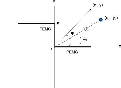
which are assumed and suppressed throughout. The geometry of the line source diffraction problem is depicted in Figure .
The wave equation satisfied by the total velocity potential in the presence of line source is
(1)
supported by the boundary conditions on the half planes located at :
(2)
on the step located at :
(3)
and the boundary condition on the step located at is:
(4)
In addition to the boundary conditions (2–4), the following continuity conditions at should also be satisfied to complete the solution of the boundary value problem.
(5)
(6)
The superscripts “+” and “” indicate that the step is approached either from left- or from right-hand side along the x-axis [Citation20,Citation21]. For analysis purposes, it is convenient to decompose the field
as follows [Citation11]:
(7)
where and
are the scattered fields,
is the field reflected from the plane located at
with relative surface impedance
, and
is the incident field. Using Equation (Equation7
(7) ) in Equation (Equation1
(1) ), incident and reflected satisfy the following wave equations.
(8)
(9)
The scattered fields and
satisfy the Helmholtz equations
(10)
(11)
For analytic convenience, we shall assume that the wave number has the positive imaginary part and
It is appropriate to define the Fourier transform pair as follows:
(12)
(13)
The solution of Equation (Equation8(8) ) is [Citation11, p. 44]
(14)
where is the Hankel function of first kind and order zero. Making change of variables
in Equation (Equation14(14) ), letting
, and using the asymptotic form of Hankel function, we obtain
(15)
where(16)
and is the angle measured from x-axis. Using the same procedure as for the incident wave, the expression for the reflected wave field from the half plane located at
having impedance
is
(17)
Using expressions (Equation7(7) ), (Equation15
(15) ), and (Equation17
(17) ) in boundary and continuity conditions (2–6) will yield
(18)
(19)
(20)
and(21)
(22)
In the region , there exists a scattered field
and satisfies the Helmholtz’s Equation (Equation10
(10) ). The Fourier transform of Equation (Equation10
(10) ) with respect to the variable x will yield
(23)
with(24)
and(25)
The solution of Equation (Equation23(23) ) satisfying the radiation conditions for
is given as
(26)
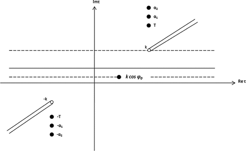
where is the complex
plane cut as shown in Figure . Such that
and
is the unknown coefficient to be determined with the aid of boundaryconditions (18–20). Fourier transform of boundary condition (Equation18
(18) ) yields
(27)
Differentiating Equation (Equation26(26) ), w. r. t the variable y will result in
(28)
Using Equation (Equation24(24) ) in Equation (Equation26
(26) ) and simplifying the resulting expression with Equation (Equation28
(28) )
will yield the expression for the undetermined coefficient
as:
(29)
where(30)
Now consider the region Here, the scattered field
exists and satisfies the Helmholtz Equation (Equation11
(11) ). The half range Fourier transform of Equation (Equation11
(11) ) w. r. t the variable x will yield
(31)
with
Using the boundary condition (Equation19(19) ) in Equation (Equation31
(31) ) and simplifying we shall arrive at
(32)
Now following the same procedure [Citation20,Citation21], i.e. multiplying both sides of Equation (Equation32(32) ) by
, we have
(33)
changing in Equation (Equation33
(33) ), we have
(34)
Subtracting Equation (Equation34(34) ) from Equation (Equation33
(33) ) will lead to a second-order homogeneous differential
(35)
The solution of Equation (Equation35(35) ) is given to be
(36)
To determine the value of the constants and
appearing in Equation (Equation36
(36) ), we employ the boundary condition (Equation20
(20) ). Its Fourier transform is
(37)
Using Equation (Equation37(37) ) into Equation (Equation36
(36) ) and simplifying will yield
(38)
Using the value of from Equation (Equation38
(38) ) into Equation (Equation36
(36) ) gives
(39)
Differentiating Equation (Equation39(39) ) with respect to the variable y and eliminating
between Equation (Equation39
(39) ) and its derivative, after setting
, will result in
(40)
where prime “/” denotes differentiation with respect to y. Finally, the Fourier transforms of continuity conditions result in(41)
and(42)
where(43)
Adding Equation (Equation41(41) ) and
times Equation (Equation42
(42) ) will result in
(44)
Also(45)
In order to calculate the functions and
appearing in Equations (Equation41
(41) ) and (Equation42
(42) ), we shall make use of Equations (Equation26
(26) ), (Equation28
(28) ), and (Equation29
(29) ) and obtain
(46)
and(47)
Using Equations (Equation46(46) ) and (Equation47
(47) ) into Equations (Equation41
(41) ) and (Equation42
(42) ) we shall arrive at
(48)
and(49)
From Equation (Equation27(27) ),
using it in Equation (Equation49
(49) ) will result
(50)
and(51)
Using Equations (Equation48(48) ), (Equation50
(50) ), and (Equation51
(51) ) in Equation (Equation40
(40) ) and simplifying will yield a modified WH equation of second kind valid within the strip of analyticity
(52)
where(53)
(54)
and(55)
Equation (Equation52(52) ) can be solved for the cases (i) when the impedances
and
are either purely capacitive i.e. of the form
with
(ii) or the impedances
and
are purely inductive i.e. of the form
with
but Büyükaksoy and Birbir [Citation20,Citation21] pointed out that the correct solution corresponds to the case when impedance
is considered purely inductive and for this the zero of the factor
does not vanish and the solution of Equation (Equation52
(52) ) is
(56)
In the above expression, stands for
=
while
is the split function, regular and free of zeros in the half plane
, resulting from the Wiener–Hopf factorization of Equation (Equation54
(54) ) as [Citation20,Citation21]:
(57)
where(58)
and(59)
The function depends upon the unknown series of constants
To find an approximate value for
substitute
in Equation (Equation56
(56) ) to get
equations in
unknowns. The simultaneous solution of these equations yields approximate solutions for
3. The far field solution
The scattered field in the region can be obtained by substituting the value of
from Equation (Equation56
(56) ) into Equation (Equation29
(29) ) and then substituting the resulting equation into Equation (Equation26
(26) ) and finally taking inverse Fourier transform we shall arrive at
(60)
where is a straight line parallel to the real axis, lying in the strip
To determine the far field behavior of the scattered field
, we introduce the substitutions
(61a)
and the transformation(61b)
where t, given in Equation (Equation61b(61b) ), is real. Omitting the details of calculations, after using Equations (Equation16
(16) ) and (Equation43
(43) ) in Equation (Equation60
(60) ), the asymptotic evaluation of the integral in Equation (Equation60
(60) ) using the method of steepest decent [Citation33] gives the scattered field due to a line source for the case when impedance
is purely inductive for large kr which is given by:
(62)
The scattered field due to a line source in a perfectly conducting (PEC) ground plane can be obtained by taking in the expression (Equation62
(62) ) and the result is
(63)
The scattered field is thus by following the procedure outlined in [Citation26], the dual scattered
can be obtained from the field
using the duality transformations as follows:
(64)
with(65a)
(65b)
where the fields and
satisfy the condition
(66)
The scattered field from a step in a PEMC plane due to a line source incidence can be obtained from expression (Equation67(67) ) which is:
(67)
where(68a)
(68b)
Next on substituting the expressions (Equation65a(65a) ), (Equation65b
(65b) ) in expressions (Equation68a
(68a) ), (Equation68b
(68b) ) and using condition (Equation66
(66) ), the scattered E and H fields from a step in a PEMC plane are found to be
(69a)
(69b)
4. Numerical results and discussion
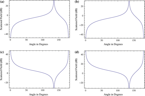
This section includes the numerical results based on the mathematical formulation of the proposed work and computer code written to get these results. In Figure , we have tried to verify the formulation and our code by reproducing the patterns for plane wave incidence on PEC and PEMC steps. For this we have taken and
From these plots, it is obvious that under special allowable limitations, our results approach to the previously published results [Citation20,Citation21]. This reveals the accuracy of our mathematical formulation and numerical code.
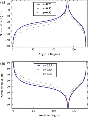
In Figure , we have presented the diffracted field from the same PEMC step when it is excited by a nearby line source. In this figure, the diffracted field has been plotted versus observation angle , for different step heights. Figure (a) shows the diffracted field when
for different step heights. Figure (b) shows the diffracted field when
for different step heights. From these two figures, it is seen that the diffracted field increases with the increase in the step height.
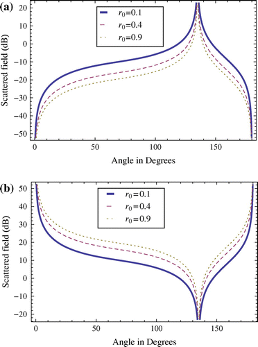
Figure exhibits the diffracted field patterns for different locations of the line source. Figure (a) shows the diffracted field when for locations of the line source in the radial direction. Figure (b) shows the diffracted field when
for locations of the line source. These two figures reveal that the diffracted field increases with the decrease in the distance of the line source from the PEMC step.
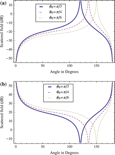
Figure shows the diffracted field patterns of a PEMC step in the presence of a nearby azimuthally located line source. Figure (a) shows the field patterns for and
when
while Figure (b) shows the diffracted field for
and
when
5. Concluding remarks
In the presence of a nearby line source diffraction by a PEMC step is investigated. It is seen from this work that like any other PEMC geometry, PEMC step is also a generalized boundary for the diffraction problem as well. Applying the special conditions in the numerical code, the results published for plane wave incidence case [Citation20,Citation21] have been reproduced for the validity of formulation and numerical code.
From the plots, it is observed that PEMC step corresponds to PEC step for and to PMC for
. And the cross-polarized component for these two cases is zero. Also for
, cross-polarized component exists and is maximum.
Numerical results also reveal that the diffracted field increases with the increase in the step height while it decreases with the increase in the distance of the line source from the PEMC step.
Notes
No potential conflict of interest was reported by the authors.
References
- Latz N. Electromagnetic diffraction by imperfectly dielectric wedges. J Math Anal Appl. 1973;43:373–387.
- Wang D. Limits and validity of the impedance boundary condition on penetrable surface. IEEE Trans Antennas Prop. 2005;163:453–457.
- Senior TBA. Diffracttion by a semi-infinite metallic sheet. Proc Roy Soc. 1952;213A:436–458.
- Jones DS, Pidduck FB. Diffraction by a metal wedge at large angles. Quart J Math Oxford. 1950;21:229–237.
- Rawlins AD. Acoustic diffraction by an absorbing semi-infinite plane in a moving fluid. Proc R Soc Edin. 1974;72:337–357.
- Ahmad B. An improved model for noise barrier in a moving fluid. J Math Anal Appl. 2006;321:609–620.
- Buyukaksoy A, Cinar G. Solution of a matrix Wiener--Hopf equation connected with the plane wave diffraction by an impedance loaded parallel plate waveguide. Math Meth Appl Sci. 2005;28:1633–1645.
- Cinar G, Büyükaksoy A. Plane wave diffraction by a slit in an impedance plane and a complementary impedance strip. Radio Sci. 2004;39:RS-2022.
- Ingard U. Influence of fluid motion past a plane boundary on sound reflection, absorption, and transmission. J Acoust Soc Am. 1959;31:1035–1036.
- Myers MK. On the acoustic boundary condition in the presence of flow. J Sound Vibr. 1980;71:429–434.
- Noble B. Methods based on the Wiener--Hopf technique. London: Pergamon Press; 1958.
- Lawrie JB, Abrahams ID. A brief historical perspective of the Wiener--Hopf technique. J Eng Math. 2007;59:351–358.
- Jones DS. The theory of electromagnetism, 602. New York: Pergamon; 1964.
- Jones DS. Aerodynamic sound due to a source near a half plane. J Inst Maths Appl. 1972;9:114–122.
- Hussain W. Asymptotic analysis of a line source diffraction by a perfectly conducting half-plane in a bi-isotropic medium. Prog Electromagn Res PIER. 2006;58:271–283.
- Ayub M, Mann AB, Ahmad M. Line source and point source scattering of acoustic waves by junction of transmissive and soft-hard planes. J Math Anal App. 2008;346:280–295.
- Ayub M, Ramzan M, Mann AB. Magnetic line source diffraction by an impedance step. IEEE Trans Antennas Propag. 2009;57:1289–1293.
- Ayub M, Ramzan M, Mann AB. Line source and point source diffraction by a reactive step. J Mod Opt. 2009;56:893–902.
- Johansen EL. Surface wave scattering by a step. IEEE Trans Antennas Propag. 1967;15:442–448.
- Buyukaksoy A, Birbir F. Plane wave diffraction by an impedance step. IEEE Trans Antennas Propag. 1993;41:1160–1164.
- Büyükaksoy A, Birbir F. Correction to plane wave diffraction by an impedance step. IEEE Trans Antennas Propag. 1996;44:422–422.
- Buyukaksoy A, Birbir F. Plane wave diffraction by a reactive step. Int J Eng Sci. 1997;35:311–319.
- Lindell IV, Sihvola AH. Perfect electromagnetic conductor. J Electromagn Waves Appl. 2005;19:861–869.
- Ruppin R. Scattering of electromagnetic radiation by a perfect electromagnetic conductor cylinder. J Electromagn Waves Appl. 2006;20:1853–1860.
- Lindell IV, Sihvola AH. Realization of the PEMC boundary. IEEE Trans Antennas Propag. 2005;53:3012–3018.
- Lindell IV, Sihvola AH. Transformation method for problems involving perfect electromagnetic conductor (PEMC) structures. IEEE Trans Antennas Propag. 2005;53:3005–3011.
- Ruppin R. Scattering of electromagnetic radiation by a perfect electromagnetic conductor sphere. J Electromagn Waves Appl. 2006;20:1569–1576.
- Ahmed S, Naqvi QA. Electromagnetic scattering from a perfectly electromagnetic conductor circular cylinder coated with a metamaterial having negative permittivity and/or permeability. Opt Commun. 2008;281:5664–5670.
- Ahmed S, Naqvi QA. Electromagnetic scattering of two or more incident plane wave by a perfect electromagnetic conductor cylinder coated with a metamaterial. Prog Electromagn Res B. 2008;10:75–90.
- Ahmed S, Naqvi QA. Electromagnetic scattering from a two dimensional perfectly electromagnetic conductor (PEMC) strip and PEMC grating simulated by circular cylinders. Opt Commun. 2008;281:4211–4218.
- Imran A, Naqvi QA, Hongo K. Diffraction of electro-magnetic plane wave from a slit in PEMC plane. Prog Electromagn Res M. 2009;8:67–77.
- Clavel E, Schanen L, Roudet J, Arechal YM. Influence of an impedance step in interconnection inductance calculation. IEEE Trans Magn. 1996;32:824–830.
- Felsen LB, Marcuvitz N. Radiation and scattering of waves. New York, NY: IEEE Press Series on Electromagnetic Waves; 1994.


