
 ?Mathematical formulae have been encoded as MathML and are displayed in this HTML version using MathJax in order to improve their display. Uncheck the box to turn MathJax off. This feature requires Javascript. Click on a formula to zoom.
ABSTRACT
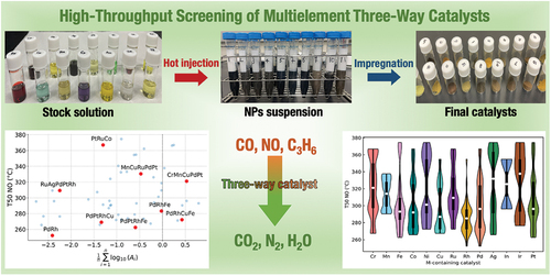
Multimetallic nanoparticles (MNPs) have appeared as promising catalysts for important catalytic reactions such as three-way catalysis (TWC) due to their synergistic effects. Herein, a comprehensive process of preparing and evaluating MNPs and supported catalysts using high-throughput experimentation (HTE) for TWC is demonstrated. The synthesis of MNPs via a hot-injection method is performed using a homemade parallel reactor. The prepared MNPs are impregnated in parallel on alumina and examined for TWC. An in-house fixed-bed reactor equipped with a quadrupole mass spectrometer was employed for catalyst evaluation, taking advantage of the rapid screening of 20 catalysts and multiple reaction conditions. The overall HTE system can facilitate the synthesis and evaluation of 51 multimetallic catalysts for TWC in less than 2 weeks, and also appear to be a flexible and versatile system for other applications.
GRAPHICAL ABSTRACT
IMPACT STATEMENT
This study outlines a comprehensive high-throughput process for synthesizing and assessing multimetallic catalysts for three-way catalysis, unveiling promising alternatives to precious metals and advancing sustainable and eco-friendly automotive emissions control.
1. Introduction
The development of three-way catalysis (TWC) has proven that the synergy between metal – metal and metal – support interactions can be a key for designing more effective and stable catalysts. The current catalytic converters mainly employ platinum group metals (PGMs) such as platinum, palladium, and rhodium. The combinations among these PGMs or between PGMs and earth-abundant metals are desired in order to improve the mass-efficiency of PGMs, thus lowering production costs. For example, binary alloys such as Pd – Rh [Citation1], Pt – Rh [Citation2], and Ir – Rh [Citation3] have been found to enhance the TWC performance compared to the corresponding monometallic catalysts. Ternary and quaternary systems consisting of PGM-free catalysts such as CuNiFe [Citation4] and FeCoNiCu [Citation5] were also reported to have comparable activity to PGM catalysts for NO reduction due to the phase stabilization against oxidation under the TWC conditions.
Although using multimetallic catalysts (MMCs) is attractive, the preparation and evaluation of these catalysts are generally cumbersome. Moreover, as multiple oxidation-reduction reactions simultaneously occur in TWC, finding an optimal condition window for evaluating the performance is challenging. Recently, the data-driven approach has been increasingly adopted in guiding the catalyst design [Citation6,Citation7] and unraveling the important characteristics of a catalyst for complex catalysis such as TWC. This approach, however, requires an adequate amount of data both for building prediction models and verifying the predicted catalysts. It should be noted that while the approach based on literature data is beneficial to quickly build a prediction model, the suggested catalysts can show large deviations when tested. This problem arises from the limitation in the literature data in describing the individual experimental environments, in particular the processes of synthesis and evaluation, which can largely differ among researchers [Citation8]. Therefore, in a ‘sustainable’ way, high-throughput experimentation (HTE) for quickly generating data and testing the prediction models is highly desired.
The idea of using HTE is not new as it has become standard practice in drug discovery and biological science. However, HTE for chemistry and material science is less developed mainly due to engineering challenges [Citation9]. Especially, HTE in automotive catalysis [Citation10–14] appears to be developing slower compared to other applications [Citation15–21] in the field of heterogeneous catalysis. hte GmbH is one of the few companies that offers high-throughput technology platforms in screening catalysts and reaction conditions for several industrial processes including TWC [Citation13]. Meanwhile, the throughput of the catalyst preparation has rarely been the focus, even though it can be the rate-determining step in the entire catalysis research. Therefore, researchers in academic labs are highly encouraged to build a simple and flexible HTE pipeline connecting the synthesis and evaluation at a comparable throughput [Citation22].
While MMCs have been realized as highly efficient and cost-effective catalysts for various important reactions [Citation23–26], starting HTE in preparation and evaluation of MMCs can be a daunting task for researchers at first glance. Here, we break down this complex process into small parts. In the first part of this paper, we demonstrate the preparation of multimetallic nanoparticles (MNPs) via a hot-injection method. This common method is categorized as a ‘bottom-up’ method, which offers NPs of small size, precise morphology, and uniform dispersion [Citation27,Citation28]. From an engineering perspective, this method is highly applicable and parallelizable since it does not require expensive equipment or complicated settings like other methods [Citation26,Citation28]. Furthermore, the preparation of a NPs suspension in a separate step can accelerate the throughput since the NPs suspension can be parallelly immobilized on multiple supports in subsequent steps.
In the next step, MNPs are immobilized on a support via wet-impregnation using a multi-position stirrer and heater. The wet-impregnation method is typically used due to the low concentration of NPs in the suspension can prevent aggregation [Citation29]. Note that in the step of NPs preparation, poly(vinylpyrrolidone) (PVP) is used as a capping/stabilizing agent. This not only affects the formation of NPs but also enhances the physical adsorption of NPs on the catalyst supports via electrostatic and polarity of the surfactant during impregnation [Citation30]. This step is followed by drying and calcination to remove the solvent and convert the deposited NPs into the active state. Since a wide range of metal combinations, whose interaction with the support can largely vary, is used in the present research, slow drying is preferable to obtain homogeneous distribution [Citation31,Citation32].
A high-speed and automated system where the effluent gases are analyzed by a quadrupole mass spectrometer (QMS) has been developed to evaluate 20 catalysts in a wide range of reaction conditions. The evaluation of multiple catalysts simultaneously offers a quick screening process while minimizing the differences in the pre-/peri-reaction, thus delivering more reliable data. The present research found that 30 catalysts out of 51 tested catalysts gave 50% conversion (T50) for CO/C3H6/NO at the temperature below 300 °C. In addition, new catalysts consisting of three to five elements are observed as effective catalysts.
2. High-throughput synthesis of multimetallic catalysts
2.1. Synthesis of multimetallic nanoparticles by hot-injection method
Herein, we demonstrate an inexpensive and accessible approach for parallelly synthesis of MNPs via a hot-injection method. The chemicals employed in the present research are comprehensively listed in Table S1. displays stock solutions containing 0.24 mmol of individual metal precursors in a solution of 1-methyl-2-pyrrolidone (NMP) and PVP (20 mg ). For some cases in which the metal precursors are less soluble, the mixtures are gently heated under vigorous stirring. In a separate flask, a solution containing triethylene glycol (TEG) and PVP (11.5 mg
) is purified by bubbling with nitrogen through a diffuser at 110 °C for at least 60 min (). To minimize moisture, reaction vials with a designed Teflon cap are heated at 200 °C under the nitrogen flow. Then, the TEG/PVP solution (20 mL) is injected into each vial and stirred for 15 min ().
Figure 1. Illustrations of the NPs synthesis process: (a) individual metal precursor solutions, (b) pretreating a TEG/PVP solution, (c) heating TEG/PVP solutions at 200 °C, (d) reaction setup with two syringes for a mixed metal solution and a reducing agent, and (E) obtained NPs suspensions.
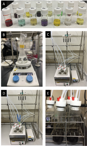
The specified amounts of the stock solutions are mixed, and 2.4 mL are transferred into a disposable syringe. Here, we assume an equimolar mixture of metal components. The syringe needle is inserted into a reaction vial through a rubber septa cap (without injecting the solution). Similarly, a syringe containing lithium triethylborohydride (LiTEBH, 2 mL) is inserted as shown in . Thereafter, the LiTEBH solution is injected first, followed by the gradual injection of the precursor solution into the hot reaction mixture. After completing the injection, the reaction is continued for an additional 30 min. When the reaction finishes, heating is stopped and the reactors are cooled under the nitrogen flow.
The obtained suspensions () are transferred into centrifugal tubes while they are still warm and less vicous. The residual reducing/stabilizing agents are washed with a mixture of acetone and hexane (3:1 v/v). In general, 20 mL of the washing solution is added to the reaction suspension. It is then vigorously shaken before being centrifugated at a speed of 10,000 rpm for 10 min. The supernatant liquid is decanted while the sedimented NPs are redispersed in methanol (5 mL) for further use. It is worth noting that the actual quantity of NPs obtained per reaction depends on the atomic weight and reactivity of the constituent elements. However, it was generally about 100 mg with an approximate yield of 90%.
2.2. Synthesis of multimetallic catalysts by impregnation
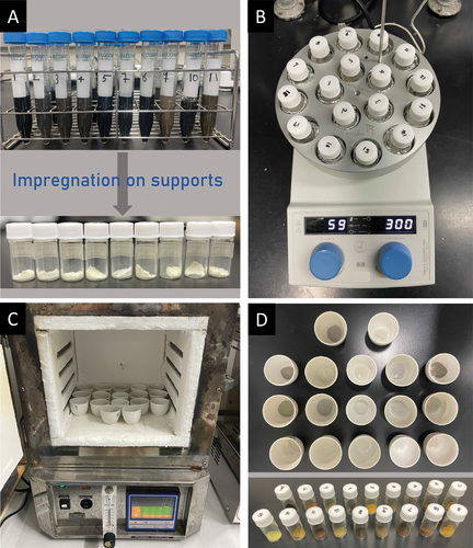
In general, the parallel synthesis of catalysts begins with the addition of support into 20 vials (). Here, we select γ-Al2O3 (200 mg) as the most commonly employed support for TWC. Depending on the metal concentrations, a certain amount of NPs suspension is then added to these vials to obtain a metal loading of 0.3 wt%. To assist the diffusion, DI water is added to increase the total volume to 2 mL. The impregnation is carried out at 60 °C while stirring at 300 rpm for 24 h (). The resulting mixtures are transferred to ceramic crucibles with the aid of a small amount of DI water. The liquid is slowly evaporated by drying in an oven at 80 °C for 24 h. The obtained solids are collected and ground finely before being calcined at 550 °C for 2 h (). Finally, the calcined samples are ground before evaluation ().
Figure 2. Illustrations of the catalyst synthesis process: (a) immpregnation of NPs on catalysts supports, (b) parallel impregnation setup, (c) drying and calcination in an oven, and (d) obtained catalysts.
3. Methods for characterizations
3.1. Characterization of nanoparticles compositions
The composition of metals in NPs suspension is quantified by an X-ray fluorescence spectrometer (XRF, PanAlytical Epsilon 3, UK) based on the external calibration method for the respective metals (Figure S1 in the Supplementary file). The XRF is equipped with an Ag X-ray tube, operated with a Cu filter having 500 m thickness. It is conducted under a potential range from 4 kV to 50 kV and a current range from 1
A to 3000
A, providing the maximum power of 15 W. To prepare the standard samples, the stock solutions of 1000 ppm (mg
) are prepared by dissolving the respective precursors in a 5% hydrochloric aqueous solution. Multielement standard solutions in different concentrations were prepared from the stock to make the calibration curves. NPs dispersed in methanol/DI water (4/6 v/v) were prepared for the measurements. Finally, 3.0 mL of a sample solution was added into a sample cup (35 mm in dia.) supported by a 6-
m thick polypropylene film. The machine can be programmed to measure 10 samples in an automated fashion with an acquisition time of 60 s. The metal compositions of all the investigated combinations are listed in Table S3. The results indicate that some metals tend to be more easily incorporated than others in the final NPs and the composition is case-sensitive due to metal – metal interaction in the synthesis. For example, the fraction of Pd is 47% in PdRh while it is 70% in PdRu.
To visualize the distribution of atomic composition data, a violin plot that shows an element-wise distribution of the incorporated concentration normalized by the theoretical concentration is provided in . Note that the theoretical atomic concentration of the corresponding element is derived based on an assumption that all the elements are fully incorporated (0.5, 0.33, 0.25, and 0.2 in binary, ternary, quaternary, and quinary combinations, respectively). The median points of box plots indicate that the PGMs generally takes larger fractions in these NPs combinations. Except for Ru, the kernel density parts in these PGMs-contaning NPs have more elongated distributions and skinny top ends compared to the other groups. This indicates that PGM tends to incorporate themselves rather than with the other elements, resulting in the dominant fractions of PGM. On the other hand, the kernel density plots of the other metals indicate that the fractions of these metals are highly concentrated around the median. This suggests that the metal fraction is dependent on the nature of the metal.
Figure 3. Incorporation of individual elements in the synthesized NPs (figure created with [Citation33]).
![Figure 3. Incorporation of individual elements in the synthesized NPs (figure created with [Citation33]).](/cms/asset/7ff2ba7b-4943-4433-8160-9f8c70ed168c/tstm_a_2284130_f0003_oc.jpg)
3.2. Characterization of nanoparticles morphology
The morphology of the synthesized NPs was observed on a transmission electron microscope (TEM, Hitachi H-7650, Japan) operating at an acceleration voltage of 100 kV. In addition, high-angle annular dark-field scanning TEM (HAADF-STEM) with elemental mapping using energy-dispersive X-ray spectroscopy (EDS) was performed on the JEM-ARM200F (JEOL U.S.A., Inc) at 200 kV. To prepare the samples, a NPs suspension in methanol was dropped onto a Cu/Mo grid and allowed to dry naturally for 12 h. The average size of particles was acquired by analyzing TEM images with the ImageJ software (Table S3). Representative TEM images are shown in , reveal that MNPs possessed an uniform size and shape, indicating the successful parallel synthesis of MNPs. The HAADF and elemental mapping images of representative NPs, including CuRh, CoRhPt, PdRhCoFe, and NiCoFePtPd, are displayed in Figures S2-5 of the Supplementary file. These images provide additional confirmation that the elements were distributed randomly and uniformly within the NPs. A histogram representing the distribution of average sizes of all the NPs is observed in . The symmetric distribution of the data set allows the approximation of the mean size of NPs by Gaussian fitting, which is approx. 3.3 nm. shows the distribution of the average size for NPs that contain a specific element. The results are consistent with the Gaussian approximation as the median points of all groups are between 3.0 and 3.5 nm, except for In-based NPs. In general, kernel density plots are wide near the median and skinny on each end, which indicates narrow size distribution in the samples.
Figure 4. Representative TEM images of prepared NPs.
Figure 5. (a) histogram of the average size for all the synthesized NPs (figure created with [Citation34]) and (b) violin plots representing the distribution of the average size for NPs containing a specific element (figure created with [Citation33]).
![Figure 5. (a) histogram of the average size for all the synthesized NPs (figure created with [Citation34]) and (b) violin plots representing the distribution of the average size for NPs containing a specific element (figure created with [Citation33]).](/cms/asset/3eb566ca-94a7-4ef2-8149-aeee4d9aa7eb/tstm_a_2284130_f0005_oc.jpg)
4. High-throughput screening of catalysts for TWC
4.1. Experiment setup
The TWC performance was evaluated using a high-throughput screening (HTS) instrument which was developed and validated in our recent publications for some other catalysis [Citation16,Citation35–37]. Basically, the HTS instrument (Figure S6 in the Supplementary file) is operated based on coordinated actions of a mixed gas generator (MU-5602, HORIBA STEC, Japan), a flow distributor, reaction quartz tubes, an electric furnace, an autosampler, and a quadrupole mass spectrometer (QMS, Transpector® CMP 3 INFICON, Switzerland). A simulated exhaust gas containing CO (13000 ppm), C3H6 (2000 ppm), NO (3000 ppm), CO2 (100000 ppm), O2 (14000 ppm), and He (balance) is provided by the mixed gas generator. The gas concentrations employed in this study were determined in accordance with an industry standard, conforming to the typical detection limit of the QMS detector, which is capable of detecting concentrations as low as 100 parts per billion (ppb). In addition, the corresponding flow rates were derived and detailed in Table S2, which fall comfortably within the controllable range of our gas mixer. The generated gas is split equally and transferred into 20 reaction quartz tubes by the flow distributor. In general, catalyst powder (60 mg) is packed between two layers of quartz wool in the neck position of the tube (inner diameter of 4 mm on the input side and 2 mm on the output site). These reaction tubes are fixed in a tube holder and placed inside the electric furnace. Temperatures at three zones along the furnace are controlled by electronic thermometers coupled with PID. The effluent gas coming out from reaction tubes is transferred to the autosampler. Here, the pneumatic actuated diaphragm valves (MEGA-ONE, Fujikin, Japan) is used to control the open/close valves to the QMS inlet. Typically, the effluent gas from 20 tubes is sequentially sampled in 1.8 s and evacuated in 12 s. In total, it requires less than 5 min/lap for generating data points for 20 catalysts.
Before the reaction, the catalysts were firstly activated at 600 °C under O2 flow for 90 min and then cooled down to room temperature. The temperature was then increased in a step of 20 °C from 100 to 400 °C with the continuous flow of the simulated reaction gas. The flow volume of the gas was fixed at 10 ccm per channel and each temperature condition was kept for 40 min, corresponding to 8 laps of QMS evaluation. The mass signal intensities generated by QMS are converted to the pressure of individual gas species relative to that of He using external calibration as shown in Figure S7 in the Supplementary file. The basic calculation of conversion is shown in EquationEquation (1)(1)
(1) ,
where ,
is the denotation of flow rate and X represents either CO, C3H6, or NO.
4.2. Screening results
compares the performance of the 51 MNPs when supported on γ-Al2O3 at a fixed amount of loading (0.3 wt%) in terms of T50 of NO, CO, and C3H6. It is noted that T50 was not measurable within the examined temperature range when no catalyst was used. The best catalyst was found to be γ-Al2O3 supported PdRh NPs, which is consistent with the previous research where PGMs were used for TWC [Citation38,Citation39]. In addition, Pd was found to be replaceable with Cu in the Rh-based bimetallic catalysts without a significant deterioration in activity. Moreover, in other multimetallic systems, combinations containing cheap and earth-abundant metals were also found. For example, PdRhNi, PdRhFe, PtRhCu, and PdRhCo are found to be good performing in the ternary system. Similarly, in quaternary and quinary systems, PdRhCoFe, PdRhCuCo, and CoNiRuRhPd exhibited low T50 values of around 250 °C.
Figure 6. Screening results for TWC (figure created with [Citation34]).
![Figure 6. Screening results for TWC (figure created with [Citation34]).](/cms/asset/78d690d2-454b-4b25-a6e6-0dcd2280b5c9/tstm_a_2284130_f0006_oc.jpg)
As lowering T50 for NO reduction is generally difficult under TWC conditions, an analysis is performed for a relationship between the observed T50 and the earth abundance of the MNPs design. The abundance of NPs combination is expressed by the arithmetic mean of the decadic logarithm of the abundance values (A) of given elements [Citation40] in that combination. It is noted that to remove the skewness of the abundance values among the investigated metals, A is transformed to , and its relationship with T50 is plotted in . Table S4 (in the Supplementary file) shows that
of precious metals is negative while it is positive for the more abundant metals. Accordingly, combinations that have positive or less negative values consist of more earth-abundant metals. The scatter plot here shows that there exists a trade-off between T50 and the abundance of MNPs design. For example, CrRuPdPtRh, MnRuPdPtRh, PdRuCo, and PdRuNi, which have increasing
-values of 1.62, 1.43, 1.14, and 0.97, showed increasing T50 values of 298.0 °C, 307.2 °C, 324.0 °C, and 340.5 °C, respectively. However, there also exists combinations with similarly high
-values at approx. 1.00 but having low T50 of less than 280 °C such as PdRhNi, and PdRhCu. Furthermore, some combinations, i.e. PdRhCoFe, PdRhCuFe, NiCoFePtPd, with positive abundance values of 0.33, 0.43, and 0.79 and having low T50 of 271.2 °C, 272.2 °C, and 293.2 °C, respectively were found. In short, the current study found that the PGMs can be replaced with cheaper metals in multimetallic catalysts to deliver comparable activities for TWC. That is, among 51 investigated combinations, 30 catalysts exhibited T50 <300 °C, and 6 catalysts having T50 <270 °C, which include PdRh, PtRh PdPtRhFe, CrCuRhPd, PdPtRhCu, and AgCoPdPtRh.
Figure 7. Relationship between the T50 of NO and the earth abundance of the MNPs design. The earth abundance of a design is derived as an average of scaled abundance of individual elements (figure created with [Citation34]).
![Figure 7. Relationship between the T50 of NO and the earth abundance of the MNPs design. The earth abundance of a design is derived as an average of scaled abundance of individual elements (figure created with [Citation34]).](/cms/asset/b68f8d79-a2ce-4cd3-a2f0-b69740cf6901/tstm_a_2284130_f0007_oc.jpg)
5. Conclusion
In conclusion, this study presents a quick and efficient process for synthesizing, characterizing, and evaluating MMCs tailored to TWC. The process enables the preparation of 10 MNPs per day via the hot-injection method, followed by catalyst preparation via the impregnation of the MNPs. Leveraging our home-made HTS system with programmable and automated sequences, we were able to simultaneously evaluate the performance of 20 catalysts under various reaction conditions. The screening results reaffirmed the importance of PGMs in TWC while highlighting the potential of earth-abundant metals including Cu, Co, Ni, and Fe as viable alternatives. By integrating high-throughput aspects into the discovery of MMCs, the present research significantly contributes to the field of automotive catalysis by enriching the TWC research toolbox and providing a platform for more efficient catalyst development. This advancement in catalyst design opens promising avenues for sustainable and cost-effective catalysts, bringing us closer to achieving cleaner and more environmentally friendly automotive emissions.
Supplemental Material
Download PDF (3.2 MB)Disclosure statement
No potential conflict of interest was reported by the author(s).
Data availability statement
The authors confirm that the data supporting the findings of this study are available within the article and its supplementary materials.
Supplementary data
Supplemental data for this article can be accessed online at https://doi.org/10.1080/27660400.2023.2284130.
Additional information
Funding
References
- Vedyagin AA, Gavrilov MS, Volodin AM, et al. Catalytic purification of exhaust gases over Pd-Rh alloy catalysts. Topics Catal. 2013;56(11):1008–10. doi: 10.1007/s11244-013-0064-8
- Dimick PS, Kross JL, Roberts EG, et al. Examining the surface of a synergistic Pt-Rh/γ-Al2O3 catalyst using NO as a probe molecule. Appl Catal B Environ. 2009;89(1–2):1–11. doi: 10.1016/j.apcatb.2008.11.025
- Haneda M, Kaneko T, Kamiuchi N, et al. Improved three-way catalytic activity of bimetallic Ir-Rh catalysts supported on CeO2-ZrO2. Catal Sci Technol. 2015;5(3):1792–1800. doi: 10.1039/C4CY01502A
- Asakura H, Kirihara M, Fujita K, et al. Fe-modified CuNi alloy catalyst as a nonprecious metal catalyst for three-way catalysis. Ind Eng Chem Res. 2020;59(45):19907–19917. doi: 10.1021/acs.iecr.0c03389
- Hirakawa T, Shimokawa Y, Miyahara Y, et al. Activity–composition relationships of Fe-Ni-Cu ternary nanoparticles supported on Al2O3 as three-way catalysts for NO reduction. ACS Appl Nano Mater. 2021;4(10):10613–10622. doi: 10.1021/acsanm.1c02087
- Pollice R, dos Passos Gomes G, Aldeghi M, et al. Data-driven strategies for accelerated materials design. Acc Chem Res. 2021;54(4):849–860. doi: 10.1021/acs.accounts.0c00785
- Takahashi K, Ohyama J, Nishimura S, et al. Catalysts informatics: paradigm shift towards data-driven catalyst design. Chem Comm. 2023;59(16):2222–2238. doi: 10.1039/D2CC05938J
- Nishimura S, Ohyama J, Kinoshita T, et al. Revisiting machine learning predictions for oxidative coupling of methane (OCM) based on literature data. ChemCatchem. 2020;12(23):5888–5892. doi: 10.1002/cctc.202001032
- Shevlin M. Practical high-throughput experimentation for chemists. ACS Med Chem Lett. 2017;8(6):601–607. doi: 10.1021/acsmedchemlett.7b00165
- Hendershot RJ, Vijay R, Snively CM, et al. High-throughput study of the performance of NOx storage and reduction catalysts as a function of cycling conditions and catalyst composition. Chem Eng Sci. 2006;61(12):3907–3916. doi: 10.1016/j.ces.2006.01.025
- Iojoiu EE, Bassou B, Guilhaume N, et al. High-throughput approach to the catalytic combustion of diesel soot. Catal Today. 2008;137(1):103–109. doi: 10.1016/j.cattod.2008.02.016
- Kern P, Klimczak M, Heinzelmann T, et al. High-throughput study of the effects of inorganic additives and poisons on NH3-SCR catalysts–part II: Fe-zeolite catalysts. Appl Catal B Environ. 2010;95(1–2):48–56. doi: 10.1016/j.apcatb.2009.12.008
- Sundermann A, Gerlach O. High-throughput screening as a supplemental tool for the development of advanced emission control catalysts: methodological approaches and data processing. Catalysts. 2016;6(2):23. doi: 10.3390/catal6020023
- Tran TPN, Thakur A, Nguyen TN, et al. Understanding chemiluminescence in catalytic oxidation of CO and hydrocarbons. CatalToday. 2021;375:56–63. doi: 10.1016/j.cattod.2020.02.034
- Chammingkwan P, Terano M, Taniike T. High-throughput synthesis of support materials for olefin polymerization catalyst. ACS Comb Sci. 2017;19(5):331–342. doi: 10.1021/acscombsci.7b00010
- Nakanowatari S, Nguyen TN, Chikuma H, et al. Extraction of catalyst design heuristics from random catalyst dataset and their utilization in catalyst development for oxidative coupling of methane. ChemCatchem. 2021;13(14):3262–3269. doi: 10.1002/cctc.202100460
- Torres JAG, Lau SH, Anchuri P, et al. A multi-objective active learning platform and web app for reaction optimization. J Am Chem Soc. 2022;144(43):19999–20007. doi: 10.1021/jacs.2c08592
- Schleinitz J, Langevin M, Smail Y, et al. Machine learning yield prediction from NiCOlit, a small-size literature data set of nickel catalyzed C–O couplings. J Am Chem Soc. 2022;144(32):14722–14730. doi: 10.1021/jacs.2c05302
- Vittoria A, Urciuoli G, Costanzo S, et al. Extending the high-throughput experimentation (HTE) approach to catalytic olefin polymerizations: from catalysts to materials. Macromolecules. 2022;55(12):5017–5026. doi: 10.1021/acs.macromol.2c00813
- Foppa L, Sutton C, Ghiringhelli LM, et al. Learning design rules for selective oxidation catalysts from high-throughput experimentation and artificial intelligence. ACS Catal. 2022;12(4):2223–2232. doi: 10.1021/acscatal.1c04793
- Takimoto K, Takeuchi K, Ton NNT, et al. Exploring stabilizer formulations for light-induced yellowing of polystyrene by high-throughput experimentation and machine learning. Polym Degrad Stab. 2022;201:109967. doi: 10.1016/j.polymdegradstab.2022.109967
- Allen CL, Leitch DC, Anson MS, et al. The power and accessibility of high-throughput methods for catalysis research. Nat Catal. 2019;2(1):2–4. doi: 10.1038/s41929-018-0220-4
- Afonso RV, Gouveia JD, Gomes JR. Catalytic reactions for H2 production on multimetallic surfaces: a review. J Phys Energy. 2021;3(3):032016. doi: 10.1088/2515-7655/ac0d9f
- Löffler T, Ludwig A, Rossmeisl J, et al. What makes high-entropy alloys exceptional electrocatalysts? Angewandte Chemie. 2021;60(52):26894–26903. doi: 10.1002/anie.202109212
- Crawley JW, Gow IE, Lawes N, et al. Heterogeneous trimetallic nanoparticles as catalysts. Chem Rev. 2022;122(6):6795–6849. doi: 10.1021/acs.chemrev.1c00493
- Yu L, Zeng K, Li C, et al. High-entropy alloy catalysts: from bulk to nano toward highly efficient carbon and nitrogen catalysis. Carbon Energy. 2022;4(5):731–761. doi: 10.1002/cey2.228
- Rossi LM, Fiorio JL, Garcia MA, et al. The role and fate of capping ligands in colloidally prepared metal nanoparticle catalysts. Dalton Trans. 2018;47(17):5889–5915. doi: 10.1039/C7DT04728B
- Kusada K, Wu D, Kitagawa H. New aspects of platinum group metal-based solid-solution alloy nanoparticles: binary to high-entropy alloys. Chem A Eur J. 2020;26(23):5105–5130. doi: 10.1002/chem.201903928
- Munnik P, de Jongh PE, de Jong KP. Recent developments in the synthesis of supported catalysts. Chem Rev. 2015;115(14):6687–6718. doi: 10.1021/cr500486u
- Costa NJ, Rossi LM. Synthesis of supported metal nanoparticle catalysts using ligand assisted methods. Nanoscale. 2012;4(19):5826–5834. doi: 10.1039/c2nr31165h
- Liu X, Khinast JG, Glasser BJ. A parametric investigation of impregnation and drying of supported catalysts. Chem Eng Sci. 2008;63(18):4517–4530. doi: 10.1016/j.ces.2008.06.013
- Noorithaya AV, Bishop C, Sarkar P, et al. Drying of supported catalysts for high metal concentrations: a reduced parameter model. Chem Eng Sci. 2019;206:361–374. doi: 10.1016/j.ces.2019.05.014
- Hunter JD. Matplotlib: a 2d graphics environment. Comput Sci Eng. 2007;9(3):90–95. doi: 10.1109/MCSE.2007.55
- OriginLab Corporation. Northampton, MA, USA: OriginLab(Pro); 2023. Version 2023. https://www.originlab.com
- Nguyen TN, Nhat TTP, Takimoto K, et al. High-throughput experimentation and catalyst informatics for oxidative coupling of methane. ACS Catal. 2019;10(2):921–932. doi: 10.1021/acscatal.9b04293
- Nguyen TN, Nakanowatari S, Nhat Tran TP, et al. Learning catalyst design based on bias-free data set for oxidative coupling of methane. ACS Catal. 2021;11(3):1797–1809. doi: 10.1021/acscatal.0c04629
- Nguyen TN, Seenivasan K, Nakanowatari S, et al. Factors to influence low-temperature performance of supported Mn-Na2WO4 in oxidative coupling of methane. Mol Catal. 2021;516:111976. doi: 10.1016/j.mcat.2021.111976
- Vedyagin AA, Kenzhin RM, Tashlanov MY, et al. Synthesis and study of bimetallic Pd–Rh system supported on zirconia-doped alumina as a component of three-way catalysts. Emiss Control Sci Technol. 2019;5(4):363–377. doi: 10.1007/s40825-019-00133-2
- Tan Z, Haneda M, Kitagawa H, et al. Slow synthesis methodology-directed immiscible octahedral Pd_xRh_{1-x} dual-atom-site catalysts for superior three-way catalytic activities over Rh. Angew Chem. 2022;134(23):e202202588. doi: 10.1002/ange.202202588
- Haynes WM, Lide DR, Bruno T. Abundance of elements in the earth’s crust and in the sea. CRC Handb Chem Phys. 2016;97(2402):14–17.