
 ?Mathematical formulae have been encoded as MathML and are displayed in this HTML version using MathJax in order to improve their display. Uncheck the box to turn MathJax off. This feature requires Javascript. Click on a formula to zoom.
Abstract
Aim
This article introduces the giant magneto-impedance-based MEG detection technique to facilitate and inspire researchers wishing to engage in related studies.
Methods
We take non-invasive brain-computer interface (BCI) as the application background, and firstly analyze the advantages of magnetoencephalography (MEG) over electroencephalography (EEG) in terms of practicality, temporal and spatial resolution, and data acquisition. Then the development status of the major MEG detection techniques are overviewed. In addition, the circuit structure and research status of GMI sensor are outlined. Finally, the future development trends and challenges of the MEG-based BCI technology and the MEG detection technique based on GMI sensor are analyzed and summarized.
Conclusion
Detecting MEG signals in an unshielded environment is a worldwide challenge. The MEG detection technique based on the GMI effect has a promising application in the field of BCI, so it is significant to conduct the investigation of this technique.
1. Introduction
Brain-computer interface (BCI) is a transformative human-computer interaction technology that directly converts specific brain signal parameters into control commands for computers or other external devices [Citation1, Citation2]. BCI provides a communication system that does not rely on traditional peripheral nerves and muscles, enabling people to express their intentions directly through this system. Thus, by attaching functionality to brain signals, the BCI system creates a new communication channel between the human brain and the computer. BCI has a wide range of potential applications in the fields of academic research, auxiliary communication, military combat, intelligent control, and rehabilitation therapy, and is receiving increasing attention [Citation3–8].
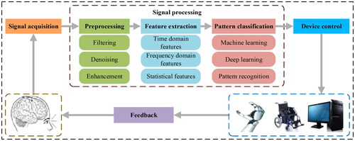
The BCI system mainly consists of input signals, output signals, the translation part from input to output, and the operation protocol. These links constitute a complex system with signal collection and matching functions. BCI can be divided into invasive and non-invasive types according to the brain signal acquisition method [Citation9–11]. Non-invasive BCI is more convenient and safer due to its non-invasive nature. In principle, any signal that can represent brain activity can be used as an input signal for BCI. These signals can be acquired in different ways, such as electroencephalography (EEG), magnetoencephalography (MEG), positron emission tomography (PET), functional magnetic resonance imaging (fMRI), functional near-infrared imaging (fNIRI), or electrical stimulation [Citation12–15]. Output signal refers to the instruction signal generated by interpreting brain activity signals, which can be used to control external devices or perform specific tasks. The translation part refers to the algorithms and models in the BCI system that are used to transform the input signals into output signals, which involves techniques such as signal preprocessing, feature extraction, pattern recognition, and machine learning. Operational protocol refers to the rules and guidelines agreed upon in the BCI system to guide the user to generate specific brain activity signals to achieve a specific operation or task. It includes the training process, intent recognition rules, and feedback mechanisms, etc., in order to ensure an effective interaction between the user and the system. So a BCI system can be described by four parts: signal acquisition, signal processing, device control, and feedback. The schematic diagram of the BCI system is shown in . The signal processing part involves operations such as preprocessing, feature extraction, and pattern classification of the acquired raw signals. The preprocessing stage includes steps such as filtering, denoising, and enhancement to eliminate noise and improve signal quality. The feature extraction phase works by extracting useful features from the signal and transforming them into a machine-understandable form. In the pattern classification stage, machine learning algorithms or pattern recognition techniques are used to map features to corresponding output categories, such as instructions or control signals.
Figure 1. Block diagram of the BCI system.
At present, the use of BCI systems is still limited to the ideal environment of a laboratory and requires professional guidance for normal use. This is due to the fact that traditional BCI systems mainly use contact measurement to obtain EEG signals and require some auxiliary processing, such as applying conductive paste and wearing electrode caps to improve the quality of the collected signals. This method has the defects of long preparation time, poor comfort of the electrode cap, poor anti-interference ability, stability, and operability not up to the practical requirements. It still falls far short of the ideal goals of “plug-and-play” and “ready-to-use” expected by practical BCI systems. In addition, the current non-invasive BCI based on EEG signals has the disadvantages of (1) low spatial resolution, which is about 10 mm; (2) low effective information, which can only be obtained in two dimensions, and the signals are interfered by the scalp and skull, and the spatiotemporal patterns that can be stably extracted are limited. Therefore, in order to improve the practical performance of BCI systems, it is of great significance to develop high-resolution portable neural interfaces to facilitate high-level communication between the brain and the system in non-surgical situations, and at the same time to realize an easy-to-use, fast-ready, high spatial resolution, strong anti-jamming capability, stable and reliable means of detecting brain signals in a normalized manner.
The brain signals recorded by MEG and EEG both originate from the synchronized activity of neurons in the brain, thus possessing homology. However, they differ in reflecting spatial information. MEG is sensitive to tangential currents and insensitive to radial currents, whereas EEG is sensitive to both. Thus, EEG reflects activity in the sulci and surfaces of the cortical layers of the brain, whereas MEG reflects activity only in the sulcal regions of the cortical layers of the brain. This means that the MEG signal has a higher spatial resolution and can precisely locate our area of interest. In addition, MEG has the advantages of easy preparation, the ability to extract complex spatiotemporal patterns, and simple and stable non-contact data acquisition. Therefore, MEG has a superior detection mechanism than EEG in principle and can replace EEG signal as the input signal of the BCI system. However, traditional means of MEG detection, such as superconducting quantum interference device (SQUID), spin-exchange relaxation-free (SERF) magnetometer, and optically pumped magnetometer (OPM), have to be used in magnetic shielding environments and the equipment is bulky and expensive, which does not meet the requirements for normalized use in the BCI field. Therefore, designing a cheap, reliable, and portable MEG detection sensor that can be used in non-magnetic shielding environments is of great significance for BCI research.
In the 1990s, Prof. Mohri discovered the giant magneto-impedance (GMI) effect in CoFeSiB amorphous wire [Citation16, Citation17]. And through subsequent research, a GMI magnetic sensor with a magnetic field resolution up to pT level was designed, successfully detecting the waves and P300 signals from the human brain in unshielded static environments [Citation18]. The weak magnetic detection technique based on GMI realizes the possibility of low-cost, miniaturization, and unshielded measurement of the human brain magnetic field. This enables MEG detection devices to develop towards miniaturization and portability, which is important for achieving human brain activity detection and improving the practicality of BCI.
The focus of this article is to sort out and analyze the principles, current status, and challenges of the MEG detection technique based on the GMI effect in the context of non-invasive BCI applications. The main contributions of this article are as follows:
The basic principles and framework of the BCI system are described, and the advantages of MEG over EEG in non-invasive BCI are analyzed in terms of practicality, temporal and spatial resolution, and data acquisition.
The advantages, disadvantages, and applications of MEG are introduced, and the research status of several current major MEG detection techniques is systematically sorted out and analyzed. Then the advantages of the GMI-based MEG detection technique are analyzed from the perspective of practical BCIs.
The principle of the GMI effect is introduced, and a comprehensive overview of the circuit structure and research status of GMI sensors is given.
The future trends of the MEG-based non-invasive BCI technology and the MEG detection technique based on the GMI effect are summarized, and the problems and challenges are further discussed.
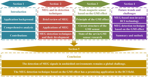
illustrates the general logic of this article, and the rest of this article is organized as follows. Section 2 briefly reviews MEG and its applications and outlines the current development status of the MEG detection technique. Section 3 introduces the basic principle of the GMI effect and describes the research progress in the field of GMI sensors from the perspective of circuit structure. The future trends and challenges of the MEG-based non-invasive BCI technology and the GMI effect-based MEG detection technique are shared in Section 4. Finally, the conclusion is given in Section 5.
Figure 2. The overall logical flow chart of this literature review.
2. MEG and its detection techniques
2.1. Brief review of MEG and its applications
MEG is a technology that locates and assesses the state of brain functional areas by measuring the bio-magnetic field of the brain. In 1968, Dr. Cohen conducted the first human MEG measurement and successfully detected the brain’s alpha rhythmic magnetic activity [Citation19]. The MEG detection process directly measures the weak bio-magnetic field signals emitted by the postsynaptic potential currents of neurons in the brain, which can be repeated multiple times without any side effects on the human body.
The advantages of MEG can be summarized as: (1) non-contact, non-invasive: MEG detection equipment does not require direct contact with the brain and has no side effects on the human body; (2) high spatiotemporal resolution: with milliseconds of temporal resolution and millimeters of spatial resolution; (3) fast and convenient: the measurement preparation time is short, and the measurement process is relatively convenient and quick; (4) obvious signal: no need for complex statistical processing, easy to analyze and interpret; (5) no interference from outer tissues: not affected by potential changes in brain outer tissues, such as the skull and scalp; (6) provide quantitative information: able to provide quantitative information about the activity intensity of neural activity groups; (7) resistant to muscle artifact: low sensitivity to artifact generated by muscle activity, and able to well distinguish real brain activity.
Of course, there are also some drawbacks of MEG, such as: (1) high requirements for the accuracy of the detection instrument; (2) the cost of the equipment is generally more expensive and complex to use, requiring specialized technicians to operate and interpret the data; (3) higher sensitivity to external magnetic fields, and most of the detection environments require magnetic shielding; and (4) higher sensitivity to changes in the shape and position of the head. These shortcomings need to be overcome and improved in future studies.
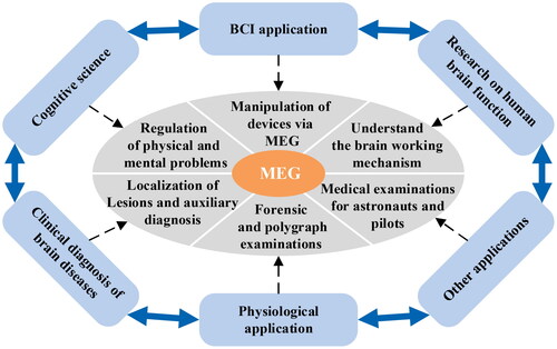
MEG has been widely applied in human brain function research [Citation20, Citation21], cognitive science [Citation22, Citation23], BCI system [Citation24, Citation25], physiology and clinical brain disease diagnosis [Citation26–28], etc., and also in the physical examination of special populations, such as astronauts and pilots, etc., as shown in . It plays an important role in various fields of brain neuroscience and provides an effective means for the study of advanced functions of the human brain.
Figure 3. Examples of MEG applications.
2.2. MEG detection techniques and their development
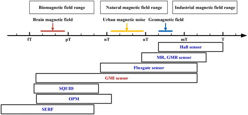
MEG technology can overcome the inherent shortcomings of EEG acquisition and provide a non-invasive, non-contact acquisition of real-time neural activity signals from the brain with high signal temporal and spatial resolution. However, the brain magnetic field, a nearly non-destructive neuromagnetic signal, is very weak, with an intensity between fT and pT outside the scalp, and is easily affected by the ambient magnetic field, which poses a great deal of difficulty for effective signal detection. Therefore, there is a need to develop magnetic detection sensors with high sensitivity and resolution. Currently, the main MEG detection techniques include SQUID, SERF magnetometer, OPM, and GMI magnetic sensor. Their technical specifications are shown in . The sensitivity of all four techniques is suitable for BCI, and the key lies in the ability to realize unshielded and wearable measurements in daily environments.
Table 1. Current major MEG detection techniques and their performance indicators.
2.2.1. SQUID
SQUID is a magnetic flux sensor that converts magnetic flux into voltage. Its basic principle is based on the superconducting Josephson effect and the phenomenon of flux quantization [Citation29]. The key component of SQUID is a loop structure made of superconducting material, which is capable of sensing small changes in the magnetic field. When an external magnetic field passes through the loop, a current is generated inside the superconductor, which is affected by small magnetic field variations, and thus the strength of the magnetic field can be measured. The noise level of SQUID is typically in the range of The SQUID is capable of achieving magnetic field measurement accuracy of fT.
In 1972, SQUID began to be used for MEG detection, which opened the chapter of using superconducting technology to reveal the mysteries of the human brain’s bio-magnetic field. As the only commercialized and widely used magnetoencephalography tool, it plays an important role in brain science research. Early SQUIDs had only a single channel and required constant movement of the sensor probe to acquire signals, which was time-consuming and labor-intensive. With the rapid development of semiconductor circuits and computers, medical imaging technology and medical information acquisition technology have been greatly improved, the design of SQUID has achieved the leap from single-channel to multi-channel, from local to overall. In the 1990s, the SQUID-based whole-head MEG measurement system was introduced, allowing MEG signals from the entire head to be captured in a single measurement. The MEG detection process does not require immobilization of the device on the patient’s head or special preparation for the patient, resulting in a short preparation time and a safe, easy detection process without any side effects on the human body. Using SQUID, researchers can non-invasively measure and analyze the weak magnetic signals generated by the brain, thereby better understanding neural activity and brain function.
It is important to note that in order to maintain a superconducting state, SQUID devices typically need to operate at extremely low temperatures, often below −296 °C, which increases the complexity and cost of the device. In addition, SQUID is very sensitive to external magnetic fields and therefore needs to work in a magnetic shielding environment to minimize interference from ambient magnetic fields. This leads to its disadvantages such as high cost, large volume, and poor applicability. To improve these problems, researchers have been continuously studying and exploring. For example, a scalp MEG system based on a 7-channel high Tc SQUID has recently emerged [Citation30, Citation31]. Nevertheless, SQUID is still widely used in fields such as medicine and neuroscience, providing researchers with important MEG signal acquisition tools.
2.2.2. SERF magnetometer
With the continuous development of optoelectronic detection and quantum manipulation technologies, significant progress has been made in atomic spin ultra-high sensitivity magnetometers based on the SERF theory [Citation32, Citation33]. Theoretical estimates suggest that the sensitivity can be on the order of [Citation34]. In such devices, the measurement of the magnetic field is usually achieved by utilizing the spin states within atoms and the interactions between atoms. Highly sensitive detection of weak magnetic fields can be realized by means of sophisticated atomic physics and quantum mechanics techniques. The development of such devices opens up entirely new possibilities for magnetic field measurements and holds broad prospects in scientific research and applications.
In 2002, Romalis et al. at Princeton University successfully built an ultra-high-sensitivity magnetic field measurement device based on the SERF principle, which realized the first magnetic field measurement using potassium (K) atoms as a sensitive source and obtained the magnetic field measurement sensitivity of [Citation35]. Subsequently, the technique was further developed and higher sensitivity of
was achieved in 2010 [Citation34]. A 2018 article provided an overview of the recent advances and applications of SERF atomic magnetometers [Citation36]. A study in 2019 developed a multi-channel SERF magnetometer for two-dimensional vector MEGs [Citation37]. A new study in 2023 built a wearable compact closed-loop SERF atomic magnetometer for MEGs [Citation38].
The ultra-high sensitivity magnetometer based on the SERF theory is affected by the noise of the magnetic field, optical field, thermal field, and so on, among which the magnetic noise is the main interference factor. Therefore, strict magnetic shielding is necessary to ensure the normal operation of the device. Meanwhile, in order to overcome the influence of temperature, vibration, and other factors on the detection sensitivity, the whole device has a large volume, which requires corresponding measures to maintain stability and accuracy. Overall, the device has important applications in fields such as magnetic field measurement and neuroscience.
2.2.3. OPM
The OPM is a device that utilizes optical methods to manipulate the spin states of atoms to achieve non-contact, highly sensitive measurements of weak magnetic fields. Its working principle is based on the quantum properties of alkali atoms and the optical pumping effect. OPM has been developed for decades, and in recent years there have been significant improvements in sensitivity and miniaturization. At present, OPM is widely applied in the fields of geophysics, medicine, biomedicine and semiconductor manufacturing.
Recently, OPM has begun to be used to measure the weak magnetic fields generated by the human body, enabling non-invasive acquisition of MEG signals [Citation39, Citation40]. In order to further improve the sensitivity of magnetic detection, researchers at the University of Nottingham, UK, have adopted a zeroing background magnetic field method to realize MEG measurements in a magnetic shielding environment. The method includes a zeroing coil and a shielded environment, resulting in a theoretical noise level of about 7–10 fT/Hz1/2 and a dynamic range of around several nT [Citation41]. In 2019, Boto et al. achieved MEG signal detection using a wearable OPM in a magnetic shielding environment and compared it with EEG [Citation42]. In 2020, researchers at Peking University developed an OPM brain magnetic activity detection device with active shielding, which achieves MEG detection in an unshielded environment by offsetting the effects of the geomagnetic field through multiple external compensating coils with a diameter of about 2 meters (the residual geomagnetic field after offsetting is less than ) [Citation43]. These research and technological developments have led to the great potential of OPM in brain science research, providing us with a very valuable tool for a deeper understanding of human brain activities [Citation44].
Compared to traditional magnetic detection techniques such as SQUID, OPM has several advantages, including no need for refrigeration, no electromagnetic interference, and faster response time. In addition, OPM can better match different head models, the distance between the sensor and the scalp is closer, the MEG signal at the sensor is stronger, and OPM does not require a traditional magnetic shielding room. Although OPM still needs to be improved in some technical aspects, it provides a broader development direction for future MEG-based BCI.
2.2.4. GMI magnetic sensor
Since the first discovery of the GMI effect in CoFeSiB amorphous wires by Prof. Mohri in 1992, it has attracted extensive attention from scholars in the field of weak magnetic detection, and has become an important research hotspot in the field of magnetic detection in the last three decades [Citation16]. Based on this principle, the designed GMI magnetic sensors have excellent performance and play an important role in a variety of applications.
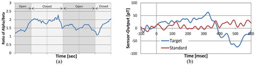
Based on years of research, Mohri et al. developed a magneto-impedance sensor with a resolution of pT level and applied it to MEG detection. In 2011, they attempted to use this sensor to measure the MEG signal at the back of the head area of a subject in an unshielded environment to assess the arousal effect and simultaneously measured the EEG signal. The results showed that the phase lag of MEG relative to EEG was about 20 ms [Citation45, Citation46]. In the same year, they improved the previously proposed synchronous detector scheme, which utilized analog switches and induction coils with a dual probe structure [Citation47]. Through the improvement, the sensitivity of the sensor was increased from 5 pT/HZ1/2 for a single probe to for a dual probe [Citation48]. Due to the optimization of the DC bias current, the internal noise level of the sensor was also reduced to near fT level [Citation49]. In 2012, they measured the brain magnetic field in the occipital region in an unshielded environment using a dual-probe pT-level resolution GMI sensor. Subjects were asked to lie flat on a flat bed and avoid body movement as much as possible to exclude interference induced by the magnetic field of the body muscles. The GMI sensor was placed 5 mm behind the occipital bone, and the magnetic field sensor was utilized to detect the MEG signals of the subjects under eye opening and eye closing, thereby achieving the detection of alpha and beta waves of brain activity. From , it can be seen that the ratio of alpha/beta becomes significantly larger after the eyes are closed [Citation18]. In 2013, they utilized the GMI sensor to detect MEG signals in the case of the oddball stimulation paradigm and without stimulation. In , the normal waveform in the no-stimulation case is shown in red, and the waveform in the stimulation case is shown in blue. The results showed that the blue waveform with stimulation appeared to change significantly around 300 ms, while the waveform without stimulation did not change, a phenomenon similar to the SQUID detection results. This shows that the GMI sensor can effectively detect the P300 signal [Citation50].
Figure 4. (a) Change in time domain waveform of the ratio of alpha/beta; (b) P300 signal under the oddball stimulation paradigm.
In their 2015 study, they performed MEG signal measurements under the P300 and N100 BCI experimental paradigms. The results showed that when the subjects underwent the N100 paradigm experiment, the peak value of the brain magnetic field measured at 5 mm away from the scalp could be up to between 15 and 25 pT; when the subjects conducted the P300 paradigm experiment, the peak value of the brain magnetic field was measured to be between 60 and 80 pT [Citation51]. In recent years, they have continued to improve the sensor system to enable real-time processing of sensor signals to monitor brain activity at room temperature [Citation52–54]. In 2020, they reduced the sensor noise level to [Citation55]. The improvement of the MEG detection technique based on the GMI magnetic sensor makes MEG detection more accurate and precise, providing a reliable tool for neuroscience research.
As shown in , Aichi Steel Company has compared the performance of common magnetic sensors on the market. The comparison results indicate that the GMI sensor offers the advantage of a wide range of magnetic field detection. Additionally, the sensor also possesses the benefits of small size, low cost, low power consumption, high sensitivity, fast response, almost no hysteresis, no need for magnetic shielding, the ability to work at room temperature, and strong stability. These advantages make the MEG detection technique based on the GMI effect a reliable, convenient, and practical method for monitoring the brain activity state, and it is considered to be the most likely MEG detection technique for BCI at present.
Figure 5. Performance comparison of various magnetic sensors.
3. Weak magnetic sensor based on the GMI effect
3.1. Principle of the GMI effect
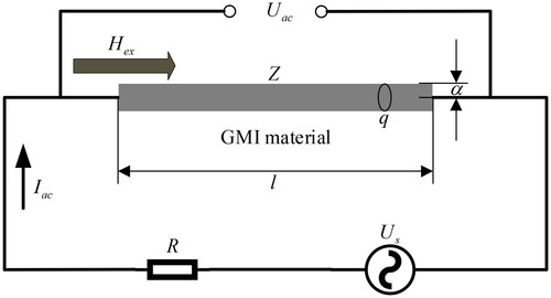
When a small high-frequency AC current is applied to a special soft magnetic conductive material (e.g. CoFeSiB amorphous wire), the AC impedance at both ends of the material will undergo significant changes with the variation of the applied axial magnetic field, which is known as the GMI effect [Citation17, Citation56–58]. The GMI effect of soft magnetic materials is usually characterized by the magneto-impedance ratio (MIR). In recent years, researchers have conducted in-depth studies on the GMI effect of various soft magnetic materials. They optimize the performance of the GMI effect by regulating the amplitude and frequency of the alternating current, the geometry, microstructure, grain size, and domain structure of the material, and other aspects to achieve higher sensitivity and stability [Citation59–63].
shows the schematic diagram of the GMI effect measurement circuit of the soft magnetic material. is an AC voltage source,
is a standard resistance through which the root-mean-square (RMS) value of AC current
flowing through the soft magnetic material can be calculated,
is the RMS value of AC voltage across the soft magnetic material, and
is the applied axial magnetic field. According to Ohm’s law, the AC impedance
of the soft magnetic material can be expressed linearly [Citation64]. In addition, the impedance
of the material can also be expressed as a function of the surface impedance tensor [Citation65].
Figure 6. The schematic diagram of the GMI effect measurement circuit.
The GMI effect can be explained by the skin effect on soft magnetic materials. In homogeneous soft magnetic materials, the change of the applied magnetic field will inevitably affect the magnetization behavior of the soft magnetic material, causing the permeability of the material to change, which in turn causes the change of the skinning depth, and therefore leads to the change of the material’s AC impedance, resulting in the GMI effect.
The AC impedance of a soft magnetic material depends on the frequency of the AC current applied to it and its magnetic permeability
Therefore, if the frequency, amplitude and waveform of the driving AC current of a soft magnetic material are certain, its impedance value
varies with its magnetic permeability
i.e. with the applied axial magnetic field
According to this property of soft magnetic materials, magnetic sensors based on the GMI effect can be designed.
3.2. Circuit structure of the GMI sensor
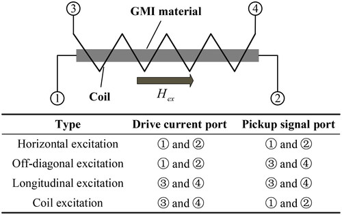
As shown in , a basic GMI magnetic sensor circuit usually consists of a GMI probe, an excitation source, a detector, a signal conditioning circuit, and an analog-to-digital (A-D) converter. According to the number of GMI probes, single-probe, dual-probe, and multi-probe GMI sensors can be designed. At present, the main use of single probe and dual probe structure. The excitation source consists of an oscillation source and a voltage-to-current (V-I) converter, which serves to generate an excitation current signal to drive the amorphous wire. The oscillation source is generally selected from sinusoidal and narrow pulse signals. The detector is used to pick up the weak signals modulated in the high-frequency excitation signal, i.e. to demodulate the signal. Commonly used detectors are peak envelope detectors and synchronous detectors. The signal conditioning circuit amplifies and filters the weak signals picked up to improve signal quality and accuracy. Finally, the A-D converter converts the signal-conditioned analog signal into a digital signal for subsequent signal analysis and processing on the computer. Based on the excitation and signal pickup methods of GMI materials, the probes of GMI sensors can be categorized into four types, namely horizontal excitation, off-diagonal excitation, longitudinal excitation, and coil excitation, as shown in . Most of the GMI sensors presented in the existing literature adopt horizontal excitation and off-diagonal excitation. The development of GMI magnetic sensor circuits employing these two excitation methods is summarized below.
Figure 7. Circuit structure of the GMI magnetic sensor.
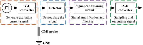
Figure 8. Four different excitation types for the GMI magnetic sensor.
In 1995, Mohri et al. designed a GMI sensor based on CoFeSiB amorphous wire using horizontal excitation and adopted the Colpitts oscillator as the excitation source and the Schottky barrier diode (SBD) as the detector [Citation66]. The sensitivity is the operating frequency range is 0–1 MHz, and the power consumption is 30–50 mV. However, this design scheme has extremely strict requirements on the component parameters of the circuit, and the oscillator will not be able to output stable self-oscillating signals if the parameters of the circuit are slightly mismatched. In addition, this design scheme needs to be applied in an electromagnetic shielding environment in order to inhibit the interference of the parasitic capacitance from the human body. In 1997, they redesigned the excitation circuit using a C-MOS multivibrator and developed a C-MOS IC GMI magnetic sensor and a C-MOS differential GMI sensor [Citation67]. Their AC sensitivity also reaches
and the power consumption is greatly reduced to
The C-MOS-based design scheme effectively reduces the requirements of the sensor circuit on the component parameters and can eliminate the interference of the human parasitic circuit, which is very conducive to the miniaturization and integration of the sensor. In addition, compared with the single probe design, the dual probes of the differential GMI sensor can effectively improve the linearity of the sensor.
In 1999, Kawajiri et al. attempted to develop a new GMI sensor by optimizing a peak detector circuit designed using a diode into a synchronous detector circuit designed using a coil and an analog switch [Citation68]. Compared with the diode peak detector circuit, the detector scheme designed with a coil and an analog switch can solve the temperature drift problem of the GMI sensor very well, and its temperature drift is also only °C Later, the researchers continued to improve the circuit, resulting in an increase in the sensitivity of the sensor to
Due to the optimization of the DC bias current, the internal noise level of the sensor was also reduced to near the
level [Citation49]. In 2009, Uchiyama et al. designed an amorphous wire GMI sensor with a 600-turn pickup coil for bio-magnetic field detection with an RMS noise of about
[Citation48]. In the following years, such pT-resolution amorphous wire magnetic sensors have been successively applied to such scenarios as the sensing of human micro vibrations transmitted along solids [Citation69], the measurement of spontaneous oscillating magnetic fields in guinea-pig smooth muscle preparations [Citation47], the measurement of bio-magnetic fields in self-generating activity muscles [Citation70] and the detection of cardiac bio-magnetic activity [Citation71]. Literature [Citation18] and [Citation46] provide a detailed review of the progress of pT-resolution amorphous wire magnetic sensors.
In 2014, Uchiyama et al. improved the sensor again from the magnetic probe and proposed a design scheme of a high-sensitivity CMOS magneto-impedance sensor based on a miniature multi-core probe [Citation72]. In the same year, Tajima et al. designed a high-resolution magneto-impedance sensor with a time analog-to-digital (TAD) converter. In order to improve the magnetic sensitivity of the GMI sensor measurement system under TAD conditions, another method of measurement using a GMI gradiometer was proposed [Citation73]. In 2016, Takiya et al. developed a first-order gradiometer-type GMI sensor and applied it to a metallic contaminant detection system [Citation74]. In order to reduce the common-mode magnetic field applied to the GMI element, they also developed a common-mode magnetic field-suppressed magneto-impedance gradiometer [Citation75] and measured magnetocardiography (MCG) signals in an unshielded environment and at room temperature using the developed gradiometer [Citation76, Citation77]. In 2017, Ma et al. designed a high-performance single-probe GMI magnetometer with a synchronous switch peak-to-peak voltage detector designed to measure extremely weak magnetic fields from nT to pT. The noise level of this GMI magnetometer is below in the frequency range of 1–100 Hz [Citation78]. In 2018, they further improved the single probe to a dual probe to develop a GMI gradiometer for MCG detection [Citation79]. Subsequent years of research did not significantly alter the circuit structure and focused on enhancing the sampling link and excitation source to further increase the performance of the sensor [Citation80, Citation81].
4. Future trends and challenges
The MEG-based non-invasive BCI technology has a competitive advantage in the future of BCI due to its non-contact nature and ease of preparation. However, the limitations of the MEG detection technique pose significant challenges in extending it from the laboratory setting to practical applications. In recent years, various MEG detection techniques have been developed, among which the GMI magnetic sensor is a new type of magnetic sensor. It has the advantages of non-magnetic shielding, high sensitivity, fast response speed, wide linear range, etc., which is in line with the ideal goals of “plug-and-play” and “ready-to-use” pursued by the BCI system. Therefore, the GMI magnetic sensor is the most likely MEG detection technique for the BCI system.
In the future, with the continuous development of science and technology, GMI magnetic sensors will develop in the direction of miniaturization, integration, and wireless, in order to improve the efficiency and convenience of the use of sensors. However, the current development of GMI magnetic sensors is still in the exploratory stage. Although Nagoya University and Aichi Steel Company in Japan claim to have developed GMI magnetic field gradiometers with a resolution as high as the pT level, most of the various types of GMI magnetic sensors that have been developed have a resolution of the nT level, which falls short of the requirements for MEG detection. Therefore, it is still a great challenge to improve the resolution, sensitivity and other performance indicators of GMI magnetic sensors through technological innovation so that they can detect MEG signals in unshielded environments.
5. Conclusion
This review introduces the basic situation of MEG and its detection techniques with non-invasive BCI as the application background, and focuses on the related research progress in weak magnetic sensors based on the GMI effect and their circuit structures. Finally, the future development trends and challenges of the MEG-based non-invasive BCI technology and the GMI effect-based MEG detection technique are analyzed and summarized. The detection of MEG signals in unshielded environments is still a global challenge. The MEG detection technique based on the GMI effect has a broad application prospect in the field of BCI, so it is of great significance to carry out the research and development of this technique.
Disclosure statement
No potential conflict of interest was reported by the author(s).
Additional information
Funding
References
- He B, Yuan H, Meng J, et al. Brain-computer interfaces. Neural Eng. 2020:131–183. doi: 10.1007/978-3-030-43395-6_4.
- Peksa J, Mamchur D. State-of-the-art on brain-computer interface technology. Sensors. 2023;23(13):6001. doi: 10.3390/s23136001.
- Värbu K, Muhammad N, Muhammad Y. Past, present, and future of EEG-based BCI applications. Sensors. 2022;22(9):3331. doi: 10.3390/s22093331.
- Zabcikova M, Koudelkova Z, Jasek R, et al. Recent advances and current trends in brain‐computer interface research and their applications. Int J Dev Neurosci. 2022;82(2):107–123. doi: 10.1002/jdn.10166.
- Anbarasan R, Gomez Carmona D, Mahendran R. Human taste-perception: brain computer interface (BCI) and its application as an engineering tool for taste-driven sensory studies. Food Eng Rev. 2022;14(3):408–434. doi: 10.1007/s12393-022-09308-0.
- Zhang N, Zhou Z, Liu Y, et al. A novel single-character visual BCI paradigm with multiple active cognitive tasks. IEEE Trans Biomed Eng. 2019;66(11):3119–3128. doi: 10.1109/TBME.2019.2900555.
- Dai W, Liu Y, Lu H, et al. Shared control based on a brain-computer interface for human-multirobot cooperation. IEEE Robot Autom Lett. 2021;6(3):6123–6130. doi: 10.1109/LRA.2021.3091170.
- Dai W, Liu Y, Lu H, et al. A shared control framework for human-multirobot foraging with brain-computer interface. IEEE Robot Autom Lett. 2021;6(4):6305–6312. doi: 10.1109/LRA.2021.3092290.
- Li X, Chen J, Shi N, et al. A hybrid steady-state visual evoked response-based brain-computer interface with MEG and EEG. Expert Syst. Appl. 2023;223:119736. doi: 10.1016/j.eswa.2023.119736.
- Islam MK, Rastegarnia A. Editorial: recent advances in EEG (non-invasive) based BCI applications. Front Comput Neurosci. 2023;17:1151852. doi: 10.3389/fncom.2023.1151852.
- Levett JJ, Elkaim LM, Niazi F, et al. Invasive brain computer interface for motor restoration in spinal cord injury: a systematic review. Neuromodulation. 2023:1–7. doi: 10.1016/j.neurom.2023.10.006.
- Sorger B, Goebel R. Real-time fMRI for brain-computer interfacing. Handb Clin Neurol. 2020;168:289–302. doi: 10.1016/B978-0-444-63934-9.00021-4.
- Susan Philip B, Prasad G, Hemanth DJ. A systematic review on artifact removal and classification techniques for enhanced MEG-based BCI systems. Brain-Comput Interfaces. 2023;10(2-4):99–113. doi: 10.1080/2326263X.2023.2233368.
- Janapati R, Dalal V, Sengupta R. Advances in modern EEG-BCI signal processing: a review. Mat Today Proc. 2023;80:2563–2566. doi: 10.1016/j.matpr.2021.06.409.
- Chugh N, Aggarwal S. Hybrid brain-computer interface spellers: a walkthrough recent advances in signal processing methods and challenges. Int J Hum Comput Interact. 2023;39(15):3096–3113. doi: 10.1080/10447318.2022.2093445.
- Mohri K, Kohsawa T, Kawashima K, et al. Magneto-inductive effect (MI effect) in amorphous wires. IEEE Trans Magn. 1992;28(5):3150–3152. doi: 10.1109/20.179741.
- Panina LV, Mohri K. Magneto‐impedance effect in amorphous wires. Appl Phys Lett. 1994;65(9):1189–1191. doi: 10.1063/1.112104.
- Uchiyama T, Mohri K, Honkura Y, et al. Recent advances of pico-Tesla resolution magneto-impedance sensor based on amorphous wire CMOS IC MI sensor. IEEE Trans Magn. 2012;48(11):3833–3839. doi: 10.1109/TMAG.2012.2198627.
- Cohen D. Magnetoencephalography: evidence of magnetic fields produced by alpha-rhythm currents. Science. 1968;161(3843):784–786. doi: 10.1126/science.161.3843.784.
- Caliskan A, Yuksel ME, Badem H, et al. A deep neural network classifier for decoding human brain activity based on magnetoencephalography. Elektron Elektrotech. 2017;23(2):63–67.
- Zubarev I, Zetter R, Halme H-L, et al. Adaptive neural network classifier for decoding MEG signals. Neuroimage. 2019;197:425–434. doi: 10.1016/j.neuroimage.2019.04.068.
- Chholak P, Kurkin SA, Hramov AE, et al. Event-related coherence in visual cortex and brain noise: an MEG study. Appl Sci. 2021;11(1):375. doi: 10.3390/app11010375.
- Niso G, Tadel F, Bock E, et al. Brainstorm pipeline analysis of resting-state data from the open MEG archive. Front Neurosci. 2019;13:284. doi: 10.3389/fnins.2019.00284.
- Ovchinnikova AO, Vasilyev AN, Zubarev IP, et al. MEG-based detection of voluntary eye fixations used to control a computer. Front Neurosci. 2021;15:619591. doi: 10.3389/fnins.2021.619591.
- Hsieh Y-W, Lee M-T, Lin Y-H, et al. Motor cortical activity during observing a video of real hand movements versus computer graphic hand movements: an MEG study. Brain Sci. 2020;11(1):6. doi: 10.3390/brainsci11010006.
- Kim J, Kim M-Y, Kwon H, et al. Feature optimization method for machine learning-based diagnosis of schizophrenia using magnetoencephalography. J Neurosci Methods. 2020;338:108688. doi: 10.1016/j.jneumeth.2020.108688.
- Babajani-Feremi A, Noorizadeh N, Mudigoudar B, et al. Predicting seizure outcome of vagus nerve stimulation using MEG-based network topology. Neuroimage Clin. 2018;19:990–999. doi: 10.1016/j.nicl.2018.06.017.
- Foldes ST, Boninger ML, Weber DJ, et al. Effects of MEG-based neurofeedback for hand rehabilitation after tetraplegia: preliminary findings in cortical modulations and grip strength. J Neural Eng. 2020;17(2):026019. doi: 10.1088/1741-2552/ab7cfb.
- Roth BJ. Biomagnetism: the first sixty years. Sensors. 2023;23(9):4218. doi: 10.3390/s23094218.
- Pfeiffer C, Ruffieux S, Jonsson L, et al. A 7-channel high-Tc SQUID-based on-scalp MEG system. IEEE Trans Biomed Eng. 2020;67(5):1483–1489. doi: 10.1109/TBME.2019.2938688.
- Andersen LM, Pfeiffer C, Ruffieux S, et al. On-scalp MEG SQUIDs are sensitive to early somatosensory activity unseen by conventional MEG. Neuroimage. 2020;221:117157. doi: 10.1016/j.neuroimage.2020.117157.
- Cao L, Tang J, Zhang Y, et al. Signal-enhanced spin-exchange relaxation-free atomic magnetometer. Sens Actuators A Phys. 2023;353:114247. doi: 10.1016/j.sna.2023.114247.
- Liu X, Zhu J, Wang S, et al. Structure optimization of non-magnetic electric heating film for spin exchange relaxation free magnetometer. Sens Int. 2023;4:100233. doi: 10.1016/j.sintl.2023.100233.
- Dang HB, Maloof AC, Romalis MV. Ultrahigh sensitivity magnetic field and magnetization measurements with an atomic magnetometer. Appl Phys Lett. 2010;97(15):151110.
- Allred JC, Lyman RN, Kornack TW, et al. High-sensitivity atomic magnetometer unaffected by spin-exchange relaxation. Phys Rev Lett. 2002;89(13):130801. doi: 10.1103/PhysRevLett.89.130801.
- Li J, Quan W, Zhou B, et al. SERF atomic magnetometer-recent advances and applications: a review. IEEE Sensors J. 2018;18(20):8198–8207. doi: 10.1109/JSEN.2018.2863707.
- Zhang G, Huang S, Xu F, et al. Multi-channel spin exchange relaxation free magnetometer towards two-dimensional vector magnetoencephalography. Opt Express. 2019;27(2):597–607. doi: 10.1364/OE.27.000597.
- Guo Q-Q, Hu T, Feng X-Y, et al. A compact and closed-loop spin-exchange relaxation-free atomic magnetometer for wearable magnetoencephalography. Chin Phys B. 2023;32(4):040702. doi: 10.1088/1674-1056/ac7e38.
- Brookes MJ, Boto E, Rea M, et al. Theoretical advantages of a triaxial optically pumped magnetometer magnetoencephalography system. Neuroimage. 2021;236:118025. doi: 10.1016/j.neuroimage.2021.118025.
- Brookes MJ, Leggett J, Rea M, et al. Magnetoencephalography with optically pumped magnetometers (OPM-MEG): the next generation of functional neuroimaging. Trends Neurosci. 2022;45(8):621–634. doi: 10.1016/j.tins.2022.05.008.
- Boto E, Holmes N, Leggett J, et al. Moving magnetoencephalography towards real-world applications with a wearable system. Nature. 2018;555(7698):657–661. doi: 10.1038/nature26147.
- Boto E, Seedat ZA, Holmes N, et al. Wearable neuroimaging: combining and contrasting magnetoencephalography and electroencephalography. Neuroimage. 2019;201:116099. doi: 10.1016/j.neuroimage.2019.116099.
- Rui Z, Wei X, Yudong D, et al. Recording brain activities in unshielded earth’s field with optically pumped atomic magnetometers. Sci Adv. 2020;6(24):1–8.
- Zhao B, Li L, Zhang Y, et al. Optically pumped magnetometers recent advances and applications in biomagnetism: a review. IEEE Sensors J. 2023;23(17):18949–18962. doi: 10.1109/JSEN.2023.3297109.
- Mohri K, Uchiyama T, Yamada M, et al. Arousal effect of physiological magnetic stimulation on elder person’s spine for prevention of drowsiness during car driving. IEEE Trans Magn. 2011;47(10):3066–3069. doi: 10.1109/TMAG.2011.2157087.
- Mohri K, Honkura Y, Panina LV, et al. Super MI sensor: recent advances of amorphous wire and CMOS-IC magneto-impedance sensor. J Nanosci Nanotechnol. 2012;12(9):7491–7495. doi: 10.1166/jnn.2012.6541.
- Uchiyama T, Mohri K, Nakayama S. Measurement of spontaneous oscillatory magnetic field of Guinea-pig smooth muscle preparation using pico-Tesla resolution amorphous wire magneto-impedance sensor. IEEE Trans Magn. 2011;47(10):3070–3073. doi: 10.1109/TMAG.2011.2148165.
- Uchiyama T, Nakayama S, Mohri K, et al. Biomagnetic field detection using very high sensitivity magnetoimpedance sensors for medical applications. Physica Status Solidi. 2009;206(4):639–643. doi: 10.1002/pssa.200881251.
- Melo LGC, Ménard D, Yelon A, et al. Optimization of the magnetic noise and sensitivity of giant magnetoimpedance sensors. J Appl Phys. 2008;103(3):033903.
- Tajima S, Uchiyama T, Okuda Y, et al. Brain activity measurement in the occipital region of the head using a magneto-impedance sensor. 2013 Seventh International Conference on Sensing Technology. p. 267–270.
- Wang K, Tajima S, Song D, et al. Auditory evoked field measurement using magneto-impedance sensors. J Appl Phys. 2015;117(17):17B306.
- Wang K, Cai C, Yamamoto M, et al. Real-time brain activity measurement and signal processing system using highly sensitive MI sensor. AIP Adv. 2017;7(5):056635.
- Ma J, Uchiyama T. Alpha rhythm and visual event-related fields measurements at room temperature using magneto-impedance sensor system. IEEE Trans Magn. 2019;55(7):1–6. doi: 10.1109/TMAG.2018.2888875.
- Uchiyama T, Ma J. Design and demonstration of novel magnetoencephalogram detectors. IEEE Trans Magn. 2019;55(7):1–8. doi: 10.1109/TMAG.2019.2895399.
- Uchiyama T, Ma J. Development of pico tesla resolution amorphous wire magneto-impedance sensor for bio-magnetic field measurements. J Magn Magn Mater. 2020;514:167148. doi: 10.1016/j.jmmm.2020.167148.
- Mohri K. Application of amorphous magnetic wires to computer peripherals. Mater Sci Eng. 1994;185(1-2):141–145. doi: 10.1016/0921-5093(94)90937-7.
- Panina LV, Mohri K, Bushida K, et al. Giant magneto-impedance and magneto-inductive effects in amorphous alloys (invited). J Appl Phys. 1994;76(10):6198–6203. doi: 10.1063/1.358310.
- Tannous C, Gieraltowski J. Giant magneto-impedance and its applications. J Mater Sci Mater Electron. 2004;15(3):125–133. doi: 10.1023/B:JMSE.0000011350.93694.91.
- Mansourian S, Bakhshayeshi A, Taghavi Mendi R. Giant magneto-impedance variation in amorphous CoFeSiB ribbons as a function of tensile stress and frequency. Phys Lett A. 2020;384(26):126657. doi: 10.1016/j.physleta.2020.126657.
- Chen Y, Zou J, Shu X, et al. Enhanced giant magneto-impedance effects in sandwich FINEMET/rGO/FeCo composite ribbons. Appl Surf Sci. 2021;545:149021. doi: 10.1016/j.apsusc.2021.149021.
- Shuai S, Lu S, Xiang Z, et al. Stress-induced giant magneto-impedance effect of amorphous CoFeNiSiPB ribbon with magnetic field annealing. J Magn Magn Mater. 2022;551:169131. doi: 10.1016/j.jmmm.2022.169131.
- Chen L, Shuai S, Lu S, et al. Impact of stress and magnetic field in annealing process on GMI and GSI effect of CoFeSiB amorphous material. J Magn Magn Mater. 2023;588:171466. doi: 10.1016/j.jmmm.2023.171466.
- Liu M, Wang Z, Meng Z, et al. Giant magnetoimpedance effect of multilayered thin film meanders formed on flexible substrates. Micromachines. 2023;14(5):1002. doi: 10.3390/mi14051002.
- Kraus L. Theory of giant magneto-impedance in the planar conductor with uniaxial magnetic anisotropy. J. Magn. Magn. Mater. 1999;195(3):764–778. doi: 10.1016/S0304-8853(99)00286-3.
- Kraus L. GMI modeling and material optimization. Sens Actuators A Phys. 2003;106(1–3):187–194. doi: 10.1016/S0924-4247(03)00164-X.
- Bushida K, Mohri K, Uchiyama T. Sensitive and quick response micro magnetic sensor using amorphous wire MI element colpitts oscillator. IEEE Trans Magn. 1995;31(6):3134–3136. doi: 10.1109/20.490305.
- Kanno T, Mohri K, Yagi T, et al. Amorphous wire MI micro sensor using C-MOS IC multivibrator. IEEE Trans Magn. 1997;33(5):3358–3360. doi: 10.1109/20.617943.
- Kawajiri N, Nakabayashi M, Cai CM, et al. Highly stable MI micro sensor using CMOS IC multivibrator with synchronous rectification. IEEE Trans Magn. 1999;35(5):3667–3669. doi: 10.1109/20.800625.
- Mohri K, Nakamura Y, Uchiyama T, et al. Sensing of human micro-vibration transmitted along solid using pico-tesla magneto-impedance sensor (pT-MI sensor). Piers Online. 2010;6(2):161–164. doi: 10.2529/PIERS090831111225.
- Nakayama S, Atsuta S, Shinmi T, et al. Pulse-driven magnetoimpedance sensor detection of biomagnetic fields in musculatures with spontaneous electric activity. Biosens Bioelectron. 2011;27(1):34–39. doi: 10.1016/j.bios.2011.05.041.
- Nakayama S, Sawamura K, Mohri K, et al. Pulse-driven magnetoimpedance sensor detection of cardiac magnetic activity. PLOS One. 2011;6(10):e25834. doi: 10.1371/journal.pone.0025834.
- Uchiyama T, Hamada N, Cai C. Highly sensitive CMOS magnetoimpedance sensor using miniature multi-core head based on amorphous wire. IEEE Trans Magn. 2014;50(11):1–4. doi: 10.1109/TMAG.2014.2326658.
- Tajima S, Okuda Y, Watanabe T, et al. High-resolution magneto-impedance sensor with TAD for low noise signal processing. IEEE Trans Magn. 2014;50(11):1–4. doi: 10.1109/TMAG.2014.2332178.
- Takiya T, Uchiyama T, Aoyama H. Development of first-order gradiometer-type MI sensor and its application for a metallic contaminant detection system. J Magn Soc Jpn. 2016;40(3):51–55. doi: 10.3379/msjmag.1605R001.
- Takiya T, Uchiyama T. Common-mode magnetic field rejection-type magneto-impedance gradiometer. J Int Counc Electr Eng. 2016;7(1):1–6.
- Takiya T, Uchiyama T. Development of active shielding-type MI gradiometer and application for magnetocardiography. IEEE Trans Magn. 2017;53(11):1–4. doi: 10.1109/TMAG.2017.2726111.
- Uchiyama T, Takiya T. Development of precise off-diagonal magnetoimpedance gradiometer for magnetocardiography. AIP Adv. 2017;7(5):056644.
- Ma J, Uchiyama T. High performance single element MI magnetometer with peak-to-peak voltage detector by synchronized switching. IEEE Trans Magn. 2017;53(11):1–4. doi: 10.1109/TMAG.2017.2712715.
- Ma J, Uchiyama T. Development of peak-to-peak voltage detector-type MI gradiometer for magnetocardiography. IEEE Trans. Magn. 2018;54(11):1–5.
- Shi K, Uchiyama T. Sensor circuit for a full-sample magneto-impedance gradiometer. IEEE Magn Lett. 2019;10:1–4. doi: 10.1109/LMAG.2019.2954808.
- Yao R, Takemura Y, Uchiyama T. High precision MI sensor with low energy consumption driven by low-frequency Wiegand pulse. AIP Adv. 2023;13(2):025201.