
Abstract
Purpose
This research aimed to describe the stress distribution of an endodontically treated tooth with a mesio-occluso-distal (MOD) cavity restored with direct composite reinforced with polyethylene and e-glass ribbon fiber.
Methods
This research was a descriptive study using the finite element method. A 3D model of the mandibular first molar solid after endodontic treatment with class II MOD preparation was prepared using Solidworks software. Finite element simulation was carried out using Abaqus software. In the first simulation, 180 N force was applied (vertically 90° perpendicular to the occlusal surface) at four points of loading: the tip of the mesiobuccal and distobuccal cusp, central fossa, and distal marginal ridge. For the second simulation, a 100 N force was applied at a 45° lateral angle to the occlusal surface at two loading points: the lingual slope of the mesiobuccal and distobuccal cusp.
Results
This study showed that the stress concentration was located in the occlusal pit and fissure, CEJ distal area, bifurcation in dentin, and the 1/3 cervical area of root dentin. The stress value generated after vertical and lateral force did not exceed the tooth and restoration’s compressive and tensile strength value. The failure occurred at the interface of enamel and composite near the loading point area due to vertical load, both on polyethylene and e-glass fiber ribbon-reinforced composite restoration. Stress distribution of an endodontically treated tooth with a MOD cavity restored with ribbon fiber-reinforced composite using the finite element method showed that the highest stress concentration occurred on the surface close to the loading point, in narrow, concave, and sharp areas, and more apically for endodontically treated teeth.
Conclusion
Neither the tooth nor restoration failed after vertical and horizontal loads. The interface between enamel and composite on the occlusal surface failed.
Introduction
Restoration for an endodontically treated tooth is an important stage in root canal treatment. The long-term success of root canal treatment is influenced by a good coronal seal of the obturated root canal provided by the restoration. The determination of the restoration depends on the amount of remaining hard tissue of the tooth, and the loss of coronal and root structure will affect the fracture resistance of the endodontically treated tooth. A systematic review study by Afrashtehfar et alCitation1 showed that the restoration success rate is linearly related to the amount of remaining tooth structure in endodontically treated teeth.Citation1–4
The mesio-occluso-distal (MOD) cavity is characterized by two separated walls, the buccal and lingual walls, without a marginal ridge to prevent cusp deflection during mastication, making the fracture of cusps more frequent.Citation5 Studies have shown that occlusal access cavity preparation reduces tooth stiffness by 14–40%, while in MOD cavities, this reduction can be as low as 20–63%.Citation4 In response to these challenges, minimal invasive restoration for endodontically treated teeth has been developed to preserve more remaining tooth structure, effectively preventing tooth fractures.Citation4,Citation6
Adhesive technology and the development of resin composites support minimal invasive cavity preparation, offering more aesthetic results directly bonded to the tooth structure. This approach is not only more practical but also time- and cost-effective compared to indirect restoration methods.Citation6,Citation7 Further, direct composite restoration can be strengthened with ribbon fiber (fiber-reinforced composite) to address the weakness of direct composite restorations.Citation7,Citation8 The wallpapering technique is a specific method for reinforcing composite with fiber. It involves using direct composite and lining the cavity wall with ribbon tape of fiber to achieve a stronger bond strength beyond the stress generated at the tooth-restoration interface.Citation9
Laboratory studies involving the loading of teeth until failure do not provide information about the amount of stress causing fracture or the stress distribution within the remaining tooth structure.Citation10,Citation11 Finite element methods, on the other hand, allow for the simulation of biomechanical behavior in teeth and materials after loading, facilitating the analysis of stress distribution.Citation12 While in vitro studies on ribbon fiber-reinforced composites with wallpapering technique has been conducted extensively, research on their stress distribution using polyethylene and e-glass fibers after root canal treatment is yet to be explored.
This study aimed to analyze the stress distribution in the mandibular first molar after root canal treatment with a MOD cavity restored using direct composite reinforced with polyethylene and e-glass ribbon fiber (wallpapering technique). This analysis was performed using the finite element method.
Materials and Methods
Pre-Processing Stage
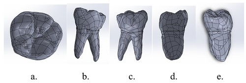
In this study, a solid 3D model of the mandibular first molar was generated after scanning with microCT and processing using 3D DOCTOR and Catia V5 software, as illustrated in . The inclusion criteria for the mandibular first molar sample involved selecting teeth with an intact crown, multiple straight roots, and a closed apex. Conversely, exclusion criteria encompassed teeth with carious lesions, fractures, restorations, calcified canals, curved roots, and open apex. The study utilized a portable computer and the Solidworks and Abaqus software for analysis.
Figure 1 Solid 3D model of mandibular first molar. (a) occlusal, (b) lingual, (c) buccal, (d) mesial, and (e) distal surface.
The material properties utilized in this study for finite element simulation are detailed in and . The bonding interface between enamel, dentin, fiber, and direct composite restoration was modeled with surface-based cohesive behavior features in Abaqus. The debonding or failure of enamel-direct composite restoration and dentin-composite restoration was observed based on the debonding criterion presented in the following equation.Citation13,Citation14
Table 1 Mechanical Properties of Tooth and Restorative Material
Table 2 Mechanical Properties of InterfaceCitation23–28
where t= contact stress (n= normal; s and t= shear) in MPa. t0= bond strength (n= normal; s and t= shear) in MPa.
In this study, a static load was employed. For the first load, a force of 180 N was applied vertically, precisely 90° perpendicular to the occlusal surface, at four points of loading: the tips of the mesiobuccal and distobuccal cusps, central fossa, and the distal marginal ridge. This force was implemented to simulate vertical motion during mastication. Subsequently, for the second load, a force of 100 N was applied at a 45° lateral angle to the occlusal surface at two loading points: the lingual slope of the mesiobuccal and distobuccal cusps. This force was applied to simulate lateral motion during mastication.
Solving Stage
The Abaqus 2021 software was employed to conduct the computation and simulation for finite element analysis.
Post-Processing Stage and Analysis
This study conducted a qualitative analysis to observe the color patterns indicating maximum and minimum principal stress. Additionally, quantitative analysis involved comparing the values of maximum and minimum principal stress with each material’s compressive and tensile strength.
Results
The 3D solid model of the first lower molar was subjected to vertical and lateral forces separately. All results are presented in . Stress concentrations were observed at the buccal groove of enamel and 1/3 of the cervical area of dentin after applying vertical loading to composite reinforced with polyethylene fiber () and e-glass fiber (). In contrast, stress concentrations were observed after lateral loading at the cervicoenamel junction and 1/3 of the cervical area of dentin ( and ). Surface stress concentrations were found on the enamel-packable composite surface for the composite reinforced with polyethylene fiber (). The composite reinforced with e-glass fiber exhibited stress concentrations on the enamel-packable composite surface and the fiber-dentin surface ().
Figure 2 Stress distribution after vertical loading on lower first molar with MOD cavity and polyethylene fiber reinforced composite on (a) enamel, (b) dentin, (c) packable composite, (d) polyethylene fiber wallpapering the cavity wall, and (e) polyethylene fiber wallpapering the cavity floor.
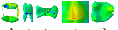
Figure 3 Stress distribution of interface between enamel and packable composite, after vertical loading on lower first molar with MOD cavity+Polyethylene fiber reinforced composite: (a) occlusal view, (b) buccal view of packable composite.
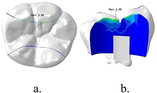
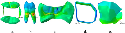
Figure 4 Stress distribution after lateral loading on lower first molar with MOD cavity and polyethylene fiber reinforced composite on (a) enamel, (b) dentin, (c) packable composite, (d) polyethylene fiber wallpapering the cavity wall, and (e) polyethylene fiber wallpapering the cavity floor.
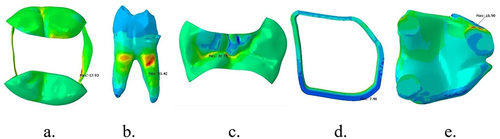
Figure 5 Stress distribution after vertical loading on lower first molar with MOD cavity and e-glass fiber reinforced composite on (a) enamel, (b) dentin, (c) packable composite, (d) e-glass fiber wallpapering the cavity wall, and (e) e-glass fiber wallpapering the cavity floor.
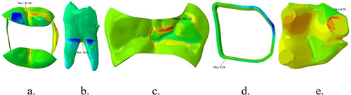
Figure 6 Stress distribution of interface between enamel-packable composite and dentin-fiber e-glass wallpapering the cavity floor after vertical loading on lower first molar with MOD cavity+ e-glass fiber reinforced composite: (a) occlusal of the tooth, (b) buccal of packable composite, (c) occlusal of fiber, and (d) e-glass fiber wallpapering the cavity floor.
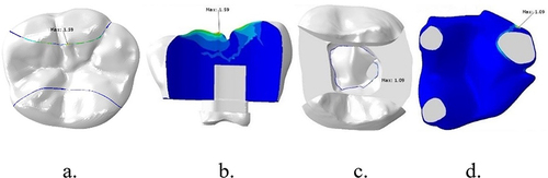
Figure 7 Stress distribution after lateral loading on lower first molar with MOD cavity and e-glass fiber reinforced composite on (a) enamel, (b) dentin, (c) packable composite, (d) e-glass fiber wallpapering the cavity wall, and (e) e-glass fiber wallpapering the cavity floor.
Following the simulation, maximum and minimum principal stress values were obtained for quantitative analysis, as presented in and . The data in and indicate that the stress generated within each material did not exceed its strength (the percentage of utility was below 100%), implying no material failure after vertical and lateral loading.
Table 3 Principal Stress for Each Component of Composite Restoration Reinforced with Polyethylene Fiber
Table 4 Principal Stress for Each Component of Composite Restoration Reinforced with e-Glass Fiber
Surface failure or debonding occurs if the contact stress ratio reaches a value of 1 or when the damage initiation criterion reaches 1.0. The data in and demonstrate failure at the enamel-packable composite surface after vertical loading with polyethylene and e-glass fiber reinforcement. The locations are illustrated in and , and for the dentin-fiber e-glass after vertical loading, as shown in .
Table 5 Value of Damage Initiation Criterion of Polyethylene Ribbon Fiber-Reinforced Composite
Table 6 Value of Damage Initiation Criterion of e-Glass Ribbon Fiber-Reinforced Composite
Discussion
Failure or fracture of the structure occurs if the minimum principal stress exceeds its tensile strength or if the maximum principal stress exceeds its compressive strength after loading. When the mastication force load is applied to the occlusion area, stress is distributed throughout the restoration and underlying tooth structure.Citation29–33
After simulation, stress concentrations were identified at the buccal groove, pit, fissure, narrow parts of enamel, and the 1/3 cervical area of the root. Maravic et alCitation34 demonstrated the highest tensile stress in the cusps area, central fissure, and cervical part of the CEJ. These areas are deep, narrow, concave, and steep.Citation29,Citation30 Stress concentration at around the 1/3 cervical area of the root dentin indicates more cusp deflection with the alveolar bone crest as a fulcrum. This differs from teeth without root canal treatment, where stress concentration in the MOD cavity without root canal treatment is located at the cervical area, more coronal than in teeth after root canal treatment.Citation35
In this study, the stress values generated were lower than the strength of both the tooth and restoration, as indicated in . This suggests that neither the tooth nor the restoration failed after vertical and lateral loading. A study by Abdulamir et alCitation32 demonstrated that adding polyethylene and e-glass fiber as reinforcing material for direct composite restoration could increase the fracture resistance of a tooth after root canal treatment with a MOD cavity. Additionally, research by Dalkilic et alCitation36 found that fractures occurred after reinforcing direct composite restoration with a fiber band above the CEJ, making the restoration more feasible.
No bevel was made in this study according to the wallpapering technique protocol.Citation4 Interestingly, this approach resulted in no enamel, dentin, composite, or fiber failures. The fracture resistance decreased as the remaining tooth structure decreased, aligning with the results of a study by Roma et al.Citation37
Bond strength represents the magnitude of force required to break the bond between two materials at the interface until failure occurs. In this study, interface failures at the enamel and composite interface near the margin of the buccal wall after vertical loading were observed in fiber-reinforced composite ( and ) and e-glass fiber with the cavity floor interface (). The stress generated at the enamel-composite interface exceeds its bond strength, initiating failure. The composite-cavity wall’s bond strength increased after the fiber insertion into the direct composite restoration. This aligns with research by Sadr et alCitation27 and Belli et alCitation38 which demonstrated higher bond strength with polyethylene fiber compared to e-glass fiber. Shah et alCitation39 also showed higher bond strength of fiber-teeth using polyethylene fiber compared to e-glass, attributing this to the superior ability of polyethylene to enhance bonding between composite and dentin.Citation38,Citation40 Remarkably, this study revealed no failure on the gingival wall. El-Mowafy et alCitation41 evaluated the effect of using polyethylene and e-glass fiber, finding a significant reduction in microleakage in the gingival area.
Conclusion
In the present study, it was found that, after the application of vertical and lateral loads on the first molar following root canal treatment with a MOD cavity restored with direct composite reinforced with polyethylene and e-glass ribbon fiber, the highest stress concentrations were located in concave, narrow, sharp areas, the cervical 1/3 of the root, and at the interface. Notably, the enamel and composite interface on the occlusal surface failed with both polyethylene and e-glass fiber. The e-glass fiber on the cavity floor and dentin also experienced failure.
It is essential to note that this study is a pilot study, and further research could enhance and complement these findings. Suggestions for future research include:
Simulation using dynamic loading
Simulation using various cavity designs
In vitro research to validate the outcomes
Variation in fiber placement location and amount of fiber layering
Simulation that includes interface adhesive microstructure.
Disclosure
The authors report no conflicts of interest in this work.
References
- Afrashtehfar KI, Ahmadi M, Emami E, Abi-Nader S, Tamimi F. Failure of single-unit restorations on root filled posterior teeth: a systematic review. Int Endod J. 2017;50(10):951–966.
- Mannocci F, Bhuva B, Roig M, et al. European Society of Endodontology position statement: the restoration of root filled teeth. Int Endod J. 2021;54(11):1974–1981. doi:10.1111/iej.13607
- Atlas A, Grandini S, Martignoni M. Evidence-based treatment planning for the restoration of endodontically treated single teeth: importance of coronal seal, post vs no post, and indirect vs direct restoration. Quintessence Int. 2019;50(10):772–781. doi:10.3290/j.qi.a43235
- Belli S, Eraslan O, Eskitascioglu G. Direct Restoration of Endodontically Treated Teeth: a Brief Summary of Materials and Techniques. Curr Oral Heal Reports. 2015;2(4):182–189. doi:10.1007/s40496-015-0068-5
- Daher R, Feilzer AJ, Krejci I. Novel non-invasive reinforcement of MOD cavities on endodontically treated teeth. J Dent. 2016;54:77–85. doi:10.1016/j.jdent.2016.09.008
- Sengun A, Cobankara FK, Orucoglu H. Effect of a new restoration technique on fracture resistance of endodontically treated teeth. Dent Traumatol. 2008;24(2):214–219. doi:10.1111/j.1600-9657.2007.00538.x
- Tekla S, Vincze-bandi E, Braunitzer G, Alleman D. Mechanical Performance of Direct Restorative Techniques Utilizing Long Fibers for “ Horizontal Splinting ” to Reinforce Deep MOD Cavities — an Updated Literature Review; 2022.
- Kumar A, Tekriwal S, Rajkumar B, Gupta V, Rastogi R. A Review on Fibre Reinforced Composite Resins. Ann Prosthodont Restor Dent. 2016;2(1):11–16.
- Deliperi S, Alleman D, Rudo D. Stress-reduced direct composites for the restoration of structurally compromised teeth: fiber design according to the “wallpapering” technique. Oper Dent. 2017;42(3):233–243. doi:10.2341/15-289-T
- Zelic K, Vukicevic A, Jovicic G, Aleksandrovic S, Filipovic N, Djuric M. Mechanical weakening of devitalized teeth: three-dimensional Finite Element Analysis and prediction of tooth fracture. Int Endodontic J. 2014;48(9):850.
- Frankenberger R, Zeilinger I, Krech M, et al. Stability of endodontically treated teeth with differently invasive restorations: adhesive vs. non-adhesive cusp stabilization. Dent Mater. 2015;31(11):1312–1320. doi:10.1016/j.dental.2015.08.160
- Daher E, Rahme AZ, Wehbe T, El Khoury CK, Badr C, Daou M. Study by finite elements of stress distribution by comparing behaviour of 2 types of composite. Int J Dent Oral Sci. 2021;8(2):1431–1436.
- Wicaksono S, Prasetia W, Muryani A, Dirgantara T, Mahyuddin AI. Finite element stress analysis of dental cement application on endocrown and onlay restoration. Aust Endod J. 2023;November 2022:1–10.
- Camanho PP, Davila CG. Mixed-Mode Decohesion Finite Elements for the Simulation of Delamination in Composite Materials. NASA Tech Pap. 2002;211737(June):42.
- Barcelos LM, Bicalho AA, Veríssimo C, Rodrigues MP, Soares CJ. Stress distribution, tooth remaining strain, and fracture resistance of endodontically treated molars restored without or with one or two fiberglass posts and direct composite resin. Oper Dent. 2017;42(6):646–657. doi:10.2341/16-224-L
- Cheron RA, Marshall SJ, Goodis HE, Peters OA. Nanomechanical Properties of Endodontically Treated Teeth. J Endod. 2011;37(11):1562–1565. doi:10.1016/j.joen.2011.08.006
- Elkholy MMA, Nawar NN, Ha WN, Saber SM, Kim HC. Impact of Canal Taper and Access Cavity Design on the Life Span of an Endodontically Treated Mandibular Molar: a Finite Element Analysis. J Endod. 2021;47(9):1472–1480. doi:10.1016/j.joen.2021.06.009
- Navimipour EJ, Firouzmandi M, Mirhashemi FS. Finite Element Analysis of the Endodontically-treated Maxillary Premolars restored with Composite Resin along with Glass Fiber Insertion in Various Positions. J Contemp Dent Pract. 2015;16(4):284–290. doi:10.5005/jp-journals-10024-1677
- Asopa S, Mandava J, Chalasani U, Anwarullah A, Ravi R. Fracture resistance of endodontically treated molars restored with resin composites. Indian J Conserv Endod. 2017;2(3):89–97.
- Lukarcanin J, Sadikoǧlu İS, Yaşa B, Türkün LŞ, Türkün M, Galli C. Comparison of Different Restoration Techniques for Endodontically Treated Teeth. Int J Biomater. 2022;2022:1–7. doi:10.1155/2022/6643825
- Halaçoglu DM, Yamanel K. The effects of different base materials on the stress distribution of the endodontically treated teeth: 3D FEA. Cumhur Dent J. 2019;22(1):56–65. doi:10.7126/cumudj.453467
- Prabhakar A, Shrikant L, Nadig B. Stress analysis in maxillary incisor following fragment reattachment: a finite element analysis. J Dent Allied Sci. 2016;5(1):7. doi:10.4103/2277-4696.185188
- Ilday N, Seven N. The influence of different fiber-reinforced composites on shear bond strengths when bonded to enamel and dentin structures. J Dent Sci. 2011;6(2):107–115. doi:10.1016/j.jds.2011.03.008
- Landys Borén D, Jonasson P, Kvist T. Long-term survival of endodontically treated teeth at a public dental specialist clinic. J Endod. 2015;41(2):176–181. doi:10.1016/j.joen.2014.10.002
- Van Landuyt KL, Kanumilli P, De Munck J, Peumans M, Lambrechts P, Van Meerbeek B. Bond strength of a mild self-etch adhesive with and without prior acid-etching. J Dent. 2006;34(1):77–85. doi:10.1016/j.jdent.2005.04.001
- Nair M, Paul J, Kumar S, Chakravarthy Y, Krishna V. Comparative evaluation of the bonding efficacy of sixth and seventh generation bonding agents: an In-Vitro study. J Conserv Dent. 2014;17(1):27–30. doi:10.4103/0972-0707.124119
- Sadr A, Bakhtiari B, Hayashi J, et al. Effects of fiber reinforcement on adaptation and bond strength of a bulk-fill composite in deep preparations. Dent Mater. 2020;36(4):527–534. doi:10.1016/j.dental.2020.01.007
- Tezvergil-Mutluay A, Lassila LVJ, Vallittu PK. Microtensile bond strength of fiber-reinforced composite with semi-interpenetrating polymer matrix to dentin using various bonding systems. Dent Mater J. 2008;27(6):821–826. doi:10.4012/dmj.27.821
- Kaladevi M, Balasubramaniam R. Biomechanics in restorative dentistry. Int J Appl Dent Sci. 2020;6(2):251–256.
- Hajira NSWN, Mehta D, Hl U. Biomechanics in Restorative Dentistry. Saarbrucken: LAP LAMBERT Academic Publishing; 2015:7–10.
- Eapen AM, Amirtharaj LV, Sanjeev K, Mahalaxmi S. Fracture Resistance of Endodontically Treated Teeth Restored with 2 Different Fiber-reinforced Composite and 2 Conventional Composite Resin Core Buildup Materials: an In Vitro Study. J Endod. 2017;43(9):1499–1504. doi:10.1016/j.joen.2017.03.031
- Abdulamir SW, Majeed MA, Paolone G. Fracture Resistance of Endodontically Treated Maxillary Premolar Teeth Restored with Wallpapering Technique: a Comparative in Vitro Study. Int J Dent. 2023;2023:1–8. doi:10.1155/2023/6159338
- Atiyah AH, Baban L. Fracture resistance of endodontically treated premolars with extensive MOD cavities restored with different composite restorations (An In vitro study). J Baghdad Coll Dent. 2014;26:7–15. doi:10.12816/0015139
- Maravić T, Comba A, Mazzitelli C, et al. Finite element and in vitro study on biomechanical behavior of endodontically treated premolars restored with direct or indirect composite restorations. Sci Rep. 2022;12(1):1–11. doi:10.1038/s41598-022-16480-0
- Soares PV, Santos-Filho PCF, Queiroz EC, et al. Fracture resistance and stress distribution in endodontically treated maxillary premolars restored with composite resin. J Prosthodont. 2008;17(2):114–119. doi:10.1111/j.1532-849X.2007.00258.x
- Eliguzeloglu Dalkiliç E, Kazak M, Hisarbeyli D, Fildisi MA, Donmez N, Deniz Arisu H. Can fiber application affect the fracture strength of endodontically treated teeth restored with a low viscosity bulk-fill composite? Biomed Res Int. 2019;2019:1–7. doi:10.1155/2019/3126931
- Roma M, Miglani S, Sureshchandra B. Fracture resistance of class ii (mod) restorations: influence of restorative technique and bevel preparation” – an in vitro study. Int J Adv Res. 2016;65(1):805–818.
- Belli S, Dönmez N, Eskitaşcioğlu G. The effect of c-factor and flowable resin or fiber use at the interface on microtensile bond strength to dentin. J Adhes Dent. 2006;8(4):247–253.
- Torabinejad M, Fouad AF, Shabahang S. Endodontics Principles and Practice. Sixth ed. missouri: Elsevier; 2021.
- Chandrasekaran N, Ramachandran AK, Vincent JC. Bond Strength in Adhesive Dentistry- A Narrative Review Abstract. IOSR J Dent Med Sci. 2022;21(11):58–62.
- El-Mowafy O, El-Badrawy W, Eltanty A, Abbasi K, Habib N. Gingival microleakage of class II resin composite restorations with fiber inserts. Oper Dent. 2007;32(3):298–305. doi:10.2341/06-86