
Figures & data

Scheme 1. Structure of tavaborole.
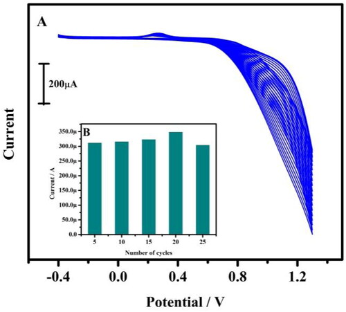
Figure 1. (A) Tentative CVs for the preparation of tavaborole/CPE. The electrolytic cell contains 1 mM tavaborole in 0.1 M NaOH at 20 multiple cycles with a scan rate of 0.05 Vs−1. (B) Relationship between anodic peak current and a total number of polymerisation cycles.
Scheme 2. Electrochemical oxidation mechanism of dopamine.
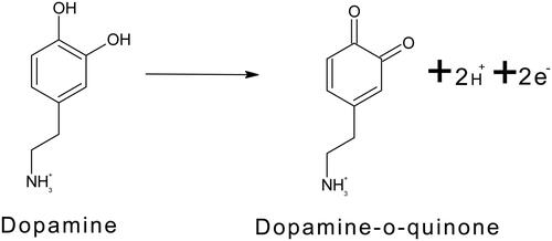
Figure 2. (A) Cyclic voltammogram of the tavaborole/MCPE in 0.2 M PBS solution containing 10 µM HQ with different pH at a scan rate of 0.05 Vs−1. (B) The graph of Ipa versus varied pH values. (C) The linearity plot of Epa versus varied pH values.
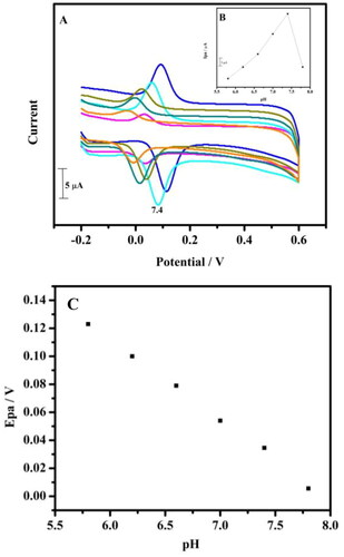
Figure 3. Cyclic voltammogram of 1 mM potassium ferrocyanide at BCPE (coloured black) and at tavaborole MCPE (coloured red) in 1 M KCl at a scan rate of 0.05 Vs−1.
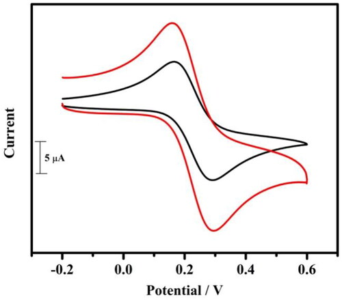
Figure 4. Cyclic voltammograms of 10 µM DA in 0.2 M PBS solution of pH 7.4 at BCPE (dotted line) and tavaborole MCPE (solid line) at a scan rate of 0.05 Vs−1.
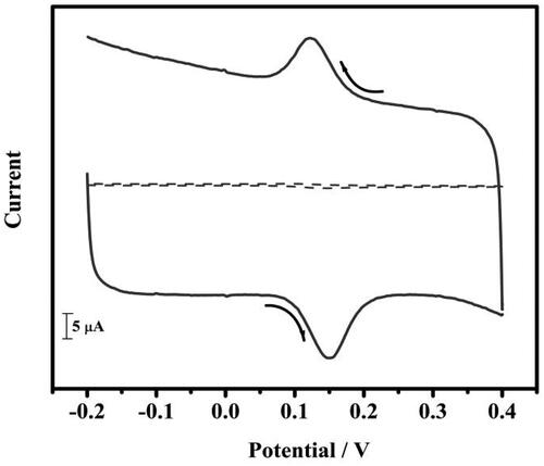
Figure 5. (A) Cyclic voltammogram of 10 µM DA in 0.2 M PBS of pH 7.4 at tavaborole MCPE with varied scan rate. (B) Graph of anodic peak current versus scan rate
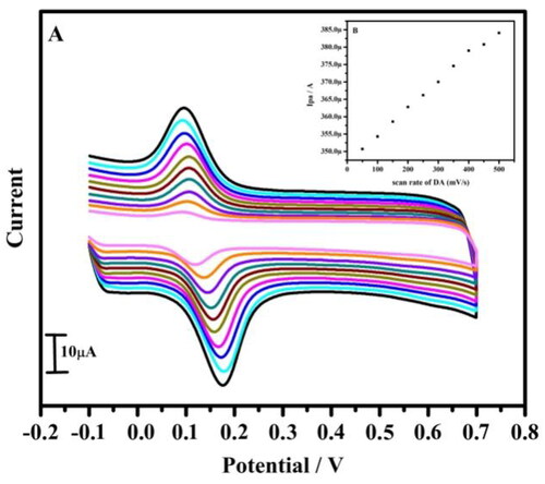
Table 1. Variation of the voltammetric parameters gathered from the plots shown in as a function of the potential sweep rate.
Figure 6. (A) Cyclic voltammogram of 10 µM DA in 0.2 M PBS of pH 7.4 at tavaborole MCPE with varied concentration at a scan rate of 0.05 Vs−1. (B) Graph of anodic peak current versus concentration.
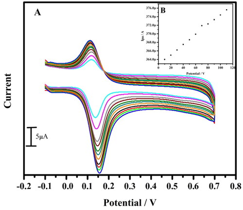
Table 2. Comparison of limit of detection with different modified electrodes and tavaborole-modified CPE.
Figure 7. Cyclic voltammogram for simultaneous determination of 10 µM DA at bare carbon paste electrode (dotted line) and tavaborole modified carbon paste electrode (solid line) at a scan rate of 0.05 Vs−1.
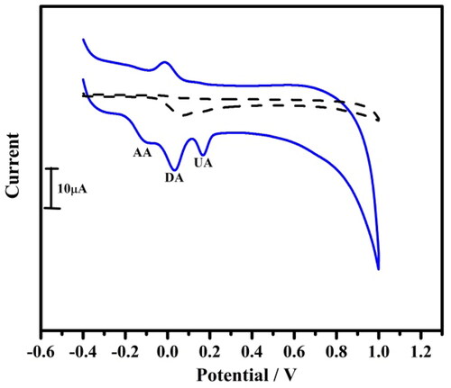
Figure 8. Linear sweep voltammogram for simultaneous determination of 10 µM DA at bare carbon paste electrode (coloured black) and tavaborole modified carbon paste electrode (coloured red) at a scan rate of 0.05 Vs−1.
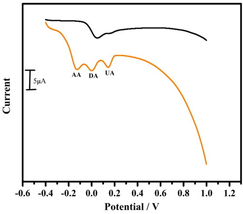
Figure 9. The cyclic voltammogram obtained for DA (10 µM–60 µM) in PBS of pH 7.4 at a scan rate of 0.05 Vs−1 in the presence of AA and UA (10 µM) at tavaborole MCPE.
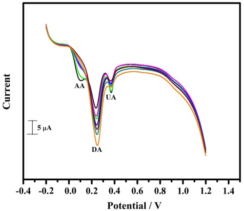
Figure 10. Cyclic voltammograms for 40 multiple cycles of 10 µM DA in 0.2 M PBS of pH 7.4 at a scan rate of 0.05 Vs−1.
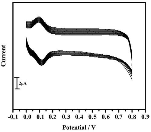
Table 3. Determination of DA in human blood serum and drug injection sample (n = 3).