
 ?Mathematical formulae have been encoded as MathML and are displayed in this HTML version using MathJax in order to improve their display. Uncheck the box to turn MathJax off. This feature requires Javascript. Click on a formula to zoom.
Abstract
This paper presents a simple, low-profile rectangular microstrip patch antenna for applications in the 28 GHz band. A regular rectangular microstrip patch antenna is initially designed. The antenna is then modified to perfectly resonate at 28 GHz and improve antenna performance in terms of S11, radiation gain, and impedance bandwidth. The antenna is optimized using inset feed to enhance the matching between the radiating patch and the feeding line. Then, a rectangular slit on the front edge of the patch is inserted with altering the antenna’s dimensions to reduce its size. The suggested antenna uses a Rogers RT/Duroid-5880 substrate with a dielectric constant of 2.2, a thickness of 0.508 mm, and a loss tangent of 0.0009. The final design is small, measuring 8 × 8.489 × 0.508 mm3 (≈ 0.75λ × 0.79λ × 0.05λ), having a maximum S11 value of - 45 dB and an impedance bandwidth of 1.43 GHz, extending from 27.28 GHz to 28.71 GHz. The radiation gain is nearly consistent over the operating band, with above 8 dBi is achieved. Besides, the proposed antenna achieves a radiation efficiency of about 99% across the band. HFSS is employed for the design, simulations, and optimizations, while CST is used to validate the HFSS simulation findings. The simulation results from both simulators indicate a high level of agreement.
IMPACT STATEMENT
The pervasive impact of wireless communication technology on daily life is evident in the rising number of users connecting their devices to wireless networks, resulting in a surge in data traffic. The increasing demand for high-speed networks, fueled by this trend, has driven the widespread adoption of fifth-generation (5G) wireless communication technology. With the capability to achieve remarkably high data rates, 5G operates in the millimeter spectrum, characterized by high losses that limit signal propagation distances and coverage. In addressing these challenges, Microstrip Patch Antennas (MSPAs) stand out as an optimal solution for 5G networks, offering advantages like compactness, lightweight design, cost-effectiveness, and ease of construction. MSPAs, recognized for their physical robustness, prove suitable for small wireless devices and high-directional antenna arrays in base stations.
REVIEWING EDITOR:
1. Introduction
In recent decades, wireless communication technology has had a significant impact on people’s daily lives. With the increasing number of individuals connecting their wireless devices to networks, there has been a surge in data traffic (Dahlman et al., Citation2014). Consequently, there is a growing demand for high-speed networks in the near future. This has led to the rise in popularity of fifth-generation (5 G) wireless communication technology, which can handle data rates up to 100 times faster than its predecessors (Diawuo & Jung, Citation2018; Mohammed et al., Citation2021). Compared to fourth-generation (4 G) networks (Paul et al., Citation2021), 5 G represents a significant advancement.
The millimeter wave radio spectrum, which operates from 3 GHz to 300 GHz, is the foundation for the next generation of 5 G technologies. This vast spectrum is mostly unutilized, allowing for the allocation of wideband channels capable of carrying high data rates to satisfy the demands of wireless network subscribers (Gkonis et al., Citation2020; Hu et al., Citation2014; Mitra & Agrawal, Citation2015; Pirinen, Citation2014; Uwaechia & Mahyuddin, Citation2020; Yau et al., Citation2018; Zikria et al., Citation2018). However, the millimeter wave spectrum has an inherent drawback of considerable path and high absorption losses, which limits the signal’s range and hence coverage (Hong et al., Citation2021; Rappaport et al., Citation2013; Wang et al., Citation2018). Among the available band spectrums for future millimeter-wave applications, the 28 GHz band stands out due to its relatively lower absorption rate and the availability of a large bandwidth (Samimi et al., Citation2013).
To effectively utilize the wideband channels and compensate for the path and absorption losses associated with this spectrum, it becomes crucial to develop antenna systems that possess small sizes, wide bandwidths, and high gains and directivities. These antenna characteristics are essential for adapting to the demands of wideband channels and mitigating the challenges posed by the millimeter wave spectrum (Hussain et al., Citation2022) and (Banday et al., Citation2019).
In this context, the technology of Microstrip Patch Antennas (MSPAs) is the best solution for 5 G wireless networks. MSPAs have the advantages of compactness, lightweight, inexpensive production, and simplicity of construction. MSPAs are also physically robust and easy to mount on any surface. All these advantages made the MSPAs a good candidate for use in small wireless devices and high-directional antenna arrays for base stations. MSPAs, however, suffer from notable drawbacks due to substrate losses, copper losses, and surface waves. These limitations result in restricted bandwidth, poor gain, and low efficiency (Mohammed et al., Citation2020; Nahas, Citation2022).
Several approaches for increasing the performance of MSPAs are discussed in the literature. Feeding techniques, defective ground structure (DGS), etching slots and slits on the ground and radiating elements, inserting metamaterial into the patch and ground plane of the antenna, changing the patch shape, partial ground techniques, and using multi-layer insulating substrates are some of these techniques (Gad & Vidmar, Citation2018; Gaid et al., Citation2019a, Citation2019b, Citation2021; Ismail et al., Citation2022).
A wide range of antenna designs for smartphones and portable devices have been developed specifically for the 28 GHz band (Awan et al., Citation2021; Farahat & Hussein, Citation2022; Hussain et al., Citation2022; Kamal et al., Citation2021, Citation2021; Paul et al., Citation2021, Citation2021, Citation2021; Paul & Saha, 2021, Citation2021, Citation2021; Przesmycki et al., Citation2020; Raheel et al., Citation2021; Rahman et al., Citation2016). For instance (Przesmycki et al., Citation2020), presents the development of a single-band rectangular inset-fed patch antenna operating at 28 GHz. With a size of 6.2 × 8.4 × 1.57 mm³ and a dielectric substrate of Rogers RT/Duroid 5880 (dielectric constant: 2.2, thickness: 1.57 mm), this antenna achieves a return loss of 22.51 dB, a VSWR of 1.162, an impedance bandwidth of 5.57 GHz, and a peak gain of 5.06 dBi. However, although this antenna offers a wide achievable impedance bandwidth, its gain falls short of the requirements for 5 G applications, which demand high-gain antennas to compensate for the significant path and absorption losses at the 28 GHz band. Additionally, low return loss and VSWR are crucial factors for effective power utilization in 5 G systems.
Another example is (Kamal et al., Citation2021), which proposes a single-band hook-shaped antenna operating at 28 GHz. With dimensions of 10 × 8 × 0.508 mm³, this antenna achieves a low return loss of approximately 36 dB, an impedance bandwidth of 6 GHz, and a gain of 3.59 dBi at its resonance frequency. Although this antenna exhibits good bandwidth and return loss characteristics, its size is not compact, and its gain is average at best.
In (Kamal et al., Citation2021), a donut-shaped antenna with dimensions of 10 × 8 × 0.256 mm³ is introduced, operating at 28 GHz with a return loss of around 38 dB. This design, utilizing a 0.256 mm thick Rogers 5880 dielectric substrate, achieves a maximum gain of 3.59 dBi and an impedance bandwidth of 6 GHz. However, this antenna’s size is relatively large, and its gain is low. Furthermore (Hussain et al., Citation2022), proposes a circular microstrip patch antenna with two rectangular slots, exhibiting an impedance bandwidth of 3.52 GHz and a gain of 7.1 dBi at the resonance frequency (28 GHz). With dimensions of 10 × 10 × 1.575 mm³, this antenna, printed on Rogers RT 5880, is relatively large in size and has a modest gain.
In (Awan et al., Citation2021), a microstrip antenna with a defective ground structure (DGS) printed on Rogers RO4003 is discussed. This antenna, measuring 5 × 5 mm2 and 0.203 mm thick, operates at 28 GHz with a 6.6 GHz impedance bandwidth, a return loss of 32 dB, and a gain of 5.62 dBi. While this design exhibits good bandwidth and return loss, its gain may still be insufficient to overcome the path and absorption losses in the millimeter wave spectrum. There is also the work of Ashiqur Rahman et al. (Rahman et al., Citation2016), who present a single-band antenna operating at 28 GHz with dimensions of 14 × 14 mm2 and a bandwidth of 2.66 GHz. However, this design is not compact, and its gain is low.
Other studies (Paul et al., Citation2021, Citation2021, Citation2021; Paul & Saha, Citation2021, Citation2021, Citation2021) propose microstrip antennas for 5 G applications in the 28 GHz band, using Rogers RT 5880 as the substrate material. These designs offer considerable bandwidth, ranging from 2.5 to 7.5 GHz, and significant gains ranging from 5.22 dB to 10.98 dB. However, all of these proposed designs have relatively large sizes, with the smallest antenna measuring 20 × 17 × 1.575 mm³.
Furthermore (Farahat & Hussein, Citation2022), introduces a patch antenna operating in the 28/38 GHz bands, printed on Rogers RO 3003 TM substrate with a dielectric constant of 3 and dimensions of 7.8 × 8.8 × 0.25 mm³. In the 28 GHz range, this patch antenna achieves a gain of 6.6 dB and a bandwidth of 1.23 GHz. Additionally (Raheel et al., Citation2021), proposes a 15 × 10 mm2 microstrip patch antenna operating at 28/38 GHz, utilizing Rogers 5880 with a thickness of 0.508 mm, a loss tangent of 0.0009, and a dielectric constant of 2.2. This design achieves a gain of 7.1 dB and an impedance bandwidth of 1 GHz (27.6 GHz - 28.6 GHz).
Some of the proposed antennas discussed above achieve wide bandwidths but have either low gains, large dimensions, or both. On the other side, some designs have large sizes while having high gains and broad bandwidths. Because of the restricted area, smartphone antenna designs must be compact. Additionally, the 28 GHz proposed by FCC, which runs from 27.5 GHz to 28.35 GHz, is characterized by its significant path loss. Therefore, the suggested antenna must thus be compact enough to fit within smartphones, have a high gain to compensate for path loss, and have enough bandwidth to cover the desired band.
The main contribution of this research is the compromise between antenna size, impedance bandwidth, and antenna gain. This tradeoff is accomplished by designing a small-size antenna with high gain, the highest S11 value, and enough impedance bandwidth to span the 28 GHz band, covering the range from 27.5 GHz to 28.35 GHz. The design and simulations are carried out using the High Frequency Structural Simulator (HFSS), which is based on the Finite Element Method (FEM). The simulation findings’ validity is checked using the Computer Studio Technology (CST) based on the Finite Integration Technique (FIT).
The remainder of the paper is organized as follows. Section 2 describes the proposed antenna’s design. Section 3 investigates the impact of various antenna parameters on S11 performance while Section 4 discusses the simulation findings for the antenna characteristics. Finally, Section 5 draws the article’s concluding remarks and outlines future work.
2. Antenna design
In this section, we detail the design process of the microstrip patch antenna proposed in this article. The start point is to decide the antenna shape and then specify the parameters of the intended antenna such as operating frequency, required impedance bandwidth, targeted gain, and radiation efficiency. To obtain good antenna characteristics, the rectangular-shape microstrip patch antenna is chosen. Initially, the proposed antenna is planned to operate at 28 GHz and cover the spectrum spanning from 27.5 GHz to 28.35 GHz. The design begins with the selection of a RT/Duroid 5880 dielectric substrate with hs = 0.508 mm substrate thickness, loss tangent (tanδ) of 0.0009, and relative permittivity (εr) of 2.2. Further, the copper sheet used for radiating element and ground plane has a thickness (hg) of 0.035 mm. To connect the microstrip transmission line to the radiating element, the inset feed is employed to get the maximum return loss and hence best matching between the microstrip feed line and the radiating element. Having decided these initial design parameters, the remaining physical dimensions of the preliminary antenna are computed using the formulas given in (Przesmycki et al., Citation2020) and (Balanis, Citation2015).
The design process is divided into three parts, the first of which is obtaining the basic design using mathematical models. The second stage is to enhance the matching between the feed line and the radiating patch, resulting in a higher return loss value at the resonant frequency. The third phase is to optimize the design by miniaturizing its size, adjusting its resonance at 28 GHz and enhancing its return loss and gain even further. These design steps are discussed in the following subsections.
2.1. The theoretical development
In this subsection, we will look quickly at all of the mathematical models applied to determine the rectangular microstrip patch antenna’ initial dimensions (Przesmycki et al., Citation2020) and (Balanis, Citation2015). We will first calculate the dimensions of the radiating patch. The width (Px) of the radiating element is found using EquationEqn. (1)(1)
(1) below.
(1)
(1)
where εr is the relative permittivity of the Rogers RT5880 dielectric substrate and c is the speed of light. To get the value of the radiating patch length, the effective permittivity (εreff) is first calculated, and then the excess length of the radiating element (ΔL) is computed as shown below.
(2)
(2)
where
represents the patch’s effective relative permittivity and hs is the substrate material thickness. ΔL, is then calculated using the following equation, EquationEqn. (3)
(3)
(3)
(3)
(3)
The actual length (Py) is then computed as follows:
(4)
(4)
Once the initial dimensions of the radiating patch are determined, the following equations are used to calculate the width (Sub x) and length (Sub y) of the dielectric substrate material.
(5)
(5)
(6)
(6)
Finally, the feed line length (Lf) and width (Wf) are attained from EquationEqn. (7)(7)
(7) through EquationEqn. (9)
(9)
(9) ,
(7)
(7)
(8)
(8)
(9)
(9)
The inset feeding technique is utilized to properly match the impedances of the microstrip line with the rectangular patch element. The inset feed gap (Ws) can be then determined using the following formula:
(10)
(10)
where fr is the operating frequency.
Using the previously mentioned models resulted in the preliminary antenna design displayed in , which has poor characteristics as demonstrated in .
Figure 1. Design steps of the proposed antenna.
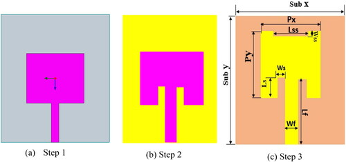
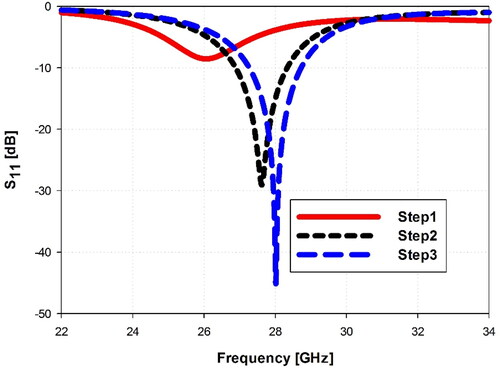
Figure 2. Simulated S11 performance of the initial and optimized antennas.
2.2. The optimized design
After identifying the initial antenna size, the 3D electromagnetic High Frequency Structural Simulator (HFSS) is utilized to conduct simulations and refine the design. depicts the design phases. The first rectangular antenna, seen in is generated using the mathematical models discussed in the previous subsection. This first patch antenna resonates at 26 GHz and has an S11 value of - 8 dB, indicating that it has no impedance bandwidth. The resonance frequency and S11 performance are gradually tuned until the desired values are obtained. The inset feed approach, as shown in , significantly improved the S11 performance to - 29 dB and shifted the resonance from 26 GHz to 27.6 GHz, bringing it closer to the 28 GHz as shown in . In addition, a rectangular slit is placed into the antenna’s front radiating patch’s edge to control the resonance at exactly 28 GHz and increase S11 performance. shows the optimized patch antenna and summarizes its optimal dimensions.
Table 1. Dimensions of the optimized design.
In terms of S11 vs operating frequencies, compares the performance of the three design processes, from the basic design to the optimized designs. The first design, as demonstrated, works at 26 GHz with an S11 of - 8 dB, but etching a rectangular slit in the radiating patch, applying the inset feed, and modifying the antenna dimensions brings the resonance frequency to exactly 28 GHz while simultaneously increasing the S11 value to - 45 dB.
3. Parametric analysis
Throughout this part, the effect of various antenna parameters on performance of the proposed antenna is carried out. The parametric analysis is performed by varying the dimensions of specific parameters and analyzing the influence of these changes on the reflection coefficient characteristics, namely the impedance bandwidth (≤ −10 dB), the operating frequency (fr), and the S11 parameter. For this experiment, the HFSS simulator’s parameter sweep function is employed. The effect of slit length (Lss), slit width (Wss), feed width (Wf), inset gap width (Ws), and the thickness (hs) of the substrate material on the antenna performance are studied. The antenna performance is also studied for different substrate materials. Finally, the effect of integrating an SMA connector is also studied.
It is important to note that throughout the paper, the terms ‘reflection coefficient’, ‘return loss’, and ‘S11’ are used interchangeably to describe the same antenna characteristic. However, when we refer to ‘return loss’, we associate it with positive numbers, whereas ‘reflection coefficient’ or ‘S11’ are associated with negative numbers.
3.1. Effects of the slit length (lss) and width (wss)
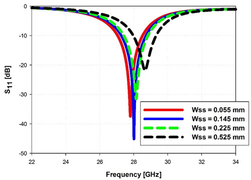
displays the reflection coefficient (S11) of the proposed antenna as a function of Lss. It has been discovered that changing the slit length produces significant variations in the reflection coefficient (S11) properties of the antenna, notably the resonance frequency and the return loss value at the resonance frequency. In this design, Lss is increased in 0.2 mm increments from 1.2 mm to 2 mm. When Lss is less than the optimal value (Lss = 1.8 mm), the resonance frequency (fr) is below 28 GHz; nevertheless, raising this parameter brings the resonance frequency closer to 28 GHz. The resonance occurs at 28 GHz when Lss = 1.8 mm. The resonance moves above 28 GHz for values greater than 1.8 mm. It is also worth mentioning that the value of the return loss changes with the length of Lss. When Lss = 1.4 mm, the return loss is roughly 48 dB, yet, fr is less than 28 GHz. The resonance occurs at 28 GHz with a return loss of 45 dB at Lss = 1.8 mm. Consequently, we concluded that the optimal value for the Lss parameter is 1.8 mm. also depicts the effect of the cut width (Wss) on the S11 performance of the antenna. The graph displays how Wss affects the return loss, the resonance frequency, and the impedance bandwidth of the proposed antenna. This parameter is assessed at four levels: 0.055 mm, 0.145 mm, 0.225 mm, and 0.525 mm. The simulations show that Wss = 0.145 mm provides the optimum performance. When Wss is less than 0.145 mm, the resonance frequency drops below 28 GHz, accompanied by a significant decrease in return loss and a minor reduction in impedance bandwidth. When the value of Wss is above 0.145 mm, the resonance frequency shifts above 28 GHz, resulting in a notable decrease in return loss and impedance bandwidth.
Figure 3. Effect of the slit length (Lss) on the S11 performance.
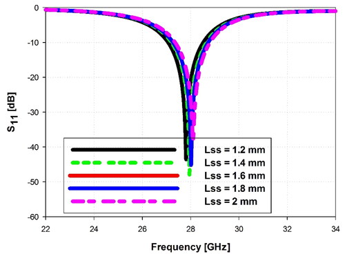
Figure 4. Effect of the slit width (Wss) on the S11 performance.
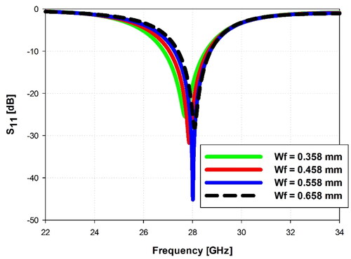
3.2. Effects of the feed line width (Wf)
The effect of Wf is examined here. The Wf value is changed from 0.358 mm to 0.658 mm in 0.1 mm increments. We can see that altering the value of Wf has a considerable effect on the impedance bandwidth, resonance frequency, and return loss value. At Wf = 0.558 mm, the optimal value for this parameter, the resonance occurs at exactly 28 GHz with a return loss value of 45 dB and impedance bandwidth of around 1.43 GHz, as shown in . As is well known, matching the characteristic impedance of the feeding line to the input impedance of the radiating element is crucial since it means that a large amount of power from the source is delivered to the radiating patch, which improves efficiency. For Wf ≤ 0.558 mm, the impedance bandwidth increases, but the resonance shifts below the intended 28 GHz and the return loss value reduces. When Wf = 0.358 mm, the return loss falls to 26 dB and the resonance moves to around 27.6 GHz. Similarly, with Wf ≥ 0.558 mm, the resonance shifts to the right of 28 GHz and the return loss value degrades, i.e. −28 dB at Wf = 0.658 mm.
Figure 5. Effect of varying the feed width (Wf) on S11 performance.
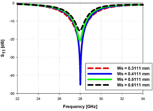
3.3. Effects of the inset gap width (Ws)
depicts the possible impact of Ws on return loss performance. It is evident that the optimized value for this parameter is Ws = 0.4111 mm, with a return loss of 45 dB. The return loss decreases for values below and above the optimal value. For example, when Ws reduces to 0.3111 mm, the return loss falls to around 21 dB. Increasing Ws over the optimal value reduces the return loss to roughly 16 dB at 0.6111 mm. It is also worth noting that this parameter does not influence the resonance frequency and has a negligible effect on the impedance bandwidth.
Figure 6. Effect of varying the inset gap width (Ws) on S11 performance.
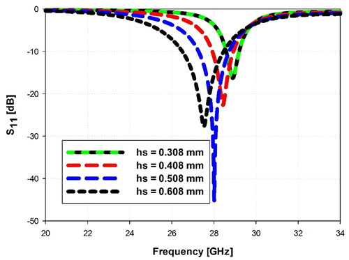
3.4. Effects of the substrate material type and its thickness (hs)
shows the impact of substrate material type on S11 performance of the antenna. This figure shows that utilizing FR4 epoxy produces dual bands around 20.8 GHz and 31 GHz. The Rogers RT 5870 generates a single band with a central frequency of 27.2 GHz. The resonance occurs sharply at 28 GHz with an excellent return loss when Rogers RT 5880 is employed as a substrate material, as shown by the curves in . Similarly, demonstrates the impact of substrate material thickness (hs) on the return loss (S11), the resonance frequency, and the impedance bandwidth. The influence is investigated at four thickness levels (0.308, 0.408, 0.508, 0.608) mm. As can be seen, the optimum value is hs = 0.508 mm, at which the antenna resonates at 28 GHz, the S11 is - 45 dB, and the impedance bandwidth is sufficient to span the desired frequency band. When the thickness is less than the optimal value, the resonance moves above 28 GHz, the S11 performance worsens, and the bandwidth narrows. When hs beyond the optimal value, the resonance shifts below 28 GHz, the S11 performance deteriorates, but the bandwidth increases.
Figure 7. Effect of substrate material type on S11 performance.
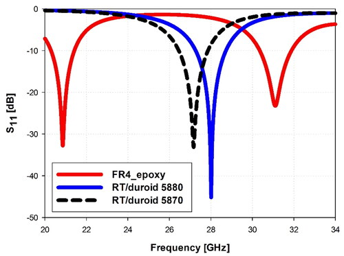
Figure 8. Effect of varying the substrate material thickness (hs) on S11 performance.
3.5. Effects of integrating an SMA connector to the feeding port
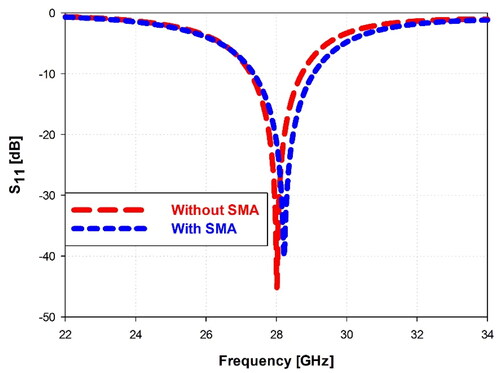
illustrates the return loss curves for the optimized design, comparing configurations with and without an SMA connector. The curves exhibit similarity, albeit with a slight shift in resonance frequency and return loss values at the resonance point. Additionally, the presence of an SMA connector contributes to an improved bandwidth.
Figure 9. Effect of an SMA integration into the feed port on the S11 performance.
4. Simulation results and discussion
This section will examine various antenna features, including the reflection coefficient (S11), voltage standing wave ratio (VSWR), two-dimensional (2D) and three-dimensional (3D) radiation characteristics, surface current distribution, antenna gain, directivity, and antenna radiation efficiency. We will assess the simulation results by examining the antenna’s various performance metrics of the optimized suggested antenna using HFSS and CST. The electromagnetic simulator HFSS is used for the simulations. Fabrication of the proposed antenna and measuring its characteristics is the most common method for verifying the validity of the simulation results. However, Yemen lacks the facilities required for the manufacture and measurement operations. To overcome this difficulty, we validate the HFSS simulation findings by running the simulations again using the CST simulator and comparing the results from the two simulators.
4.1. The reflection coefficient
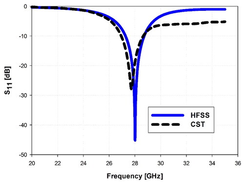
depicts the reflection coefficient (S11) curves for the proposed antenna generated by the two simulators. Although CST predicts a slightly wider impedance bandwidth than HFSS, the return loss obtained from HFSS is substantially better than that from CST (S11 ≈ −28 dB as expected by CST). Furthermore, the resonance occurs at 28 GHz, as anticipated by HFSS, although the resonant frequency predicted by CST is also somewhat lower than 28 GHz (at fr ≈ 27.7 GHz). Nonetheless, there is considerable agreement between the HFSS and CST return loss curves. indicates that the suggested antenna resonates at exactly 28 GHz with a return loss of 45 dB and an impedance bandwidth (≤ −10 dB) of 1.43 GHz (27.28 – 28.71 GHz) when considering the HFSS findings.
Figure 10. Simulated S11 performance of the proposed antenna using HFSS and CST.
4.2. The VSWR
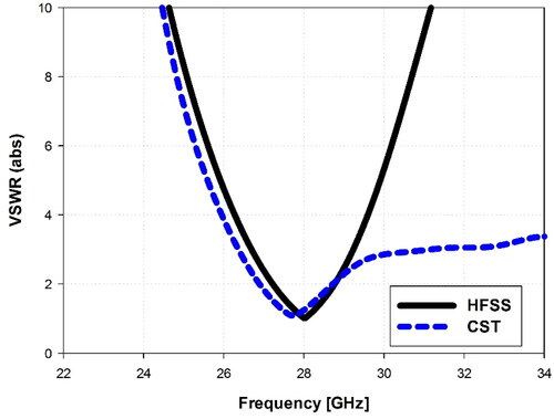
displays the proposed antenna’s VSWR performance. Within the operational band, the HFSS and CST-produced curves are similar. We can observe that the VSWR value at the resonance is 1.067. The VSWR ≤ 2 across the operating band indicates good matching between the feeding line and the radiating patch element. It is also interesting to note that the VSWR curve produced by CST (the blue line) increases slowly with frequencies beyond 28.8 GHz, but the HFSS curve (the black line) varies rapidly. For frequencies above 28.8 GHz, there appears to be a gap between the CST and HFSS curves, indicating a disagreement between CST and HFSS. This discrepancy, however, occurs beyond the antenna’s upper frequency of the operating band (28.71 GHz). It is worth noting that the gradual shift in the VSWR CST curve conforms to the slow variation in the S11 CST curve seen in , where the curve remains roughly between - 8 dB and - 6 dB above the working band’s upper frequency. When we know that S11 and VSWR are related, it will be easy to see the compatibility between the curves in and .
Figure 11. Simulated VSWR of the proposed antenna using HFSS and CST.
4.3. Radiation characteristics
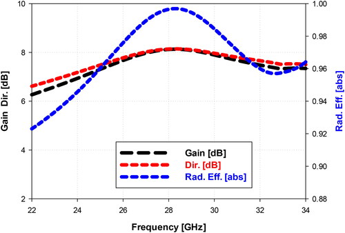
The antenna gain is another critical performance criterion defined as the antenna’s ability to transmit and receive in a specific direction. Two factors determine the antenna gain: antenna directivity and antenna radiation efficiency. The CST and HFSS 3D radiation patterns for the proposed design at the resonance frequency are shown in . These 3D radiation patterns show that antenna radiation is directional, with HFSS predicting a maximum gain of 8.1 dB and CST predicting a peak gain of 7.57 dB. Furthermore, depicts the 2D radiation patterns in the E and H planes at 28 GHz (the band’s central frequency), 27.28 GHz (the band’s lower frequency), and 28.71 GHz (the band’s upper frequency). There is a good agreement between the simulated HFSS and CST radiation patterns as clearly seen. The 2D radiation patterns show good antenna directionality, with maximal radiation occurring in the boresight direction of the radiating patch and a 3 dB beamwidth of roughly 72 degrees. depicts the gain, directivity, and radiation efficiency with the operating frequencies. We can see that the antenna gain is nearly consistent over the operational band where it is above 8 dB over the whole frequency band extending from 27.28 GHz to 28.71 GHz. In contrast, the antenna’s directivity at the resonance frequency is 8.182 dB (as predicted by HFSS) and 8.498 dB (as estimated by CST). Furthermore, HFSS overestimates the antenna’s radiation efficiency by around 99% across the whole working range, whereas CST expects an antenna’s radiation efficiency of about 89.1% and a total efficiency of approximately 88%. Good antenna matching and adoption of low-loss substrate material lead to high radiation and total efficiency. We believe that the efficiencies indicated by CST are more reasonable than those anticipated by HFSS are, thus we will consider these estimates.
Figure 12. The 3D radiation patterns of the proposed antenna, (a) HFSS, (b) CST.
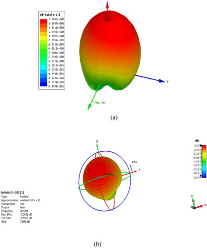
Figure 13. Simulated 2D radiation patterns at (a) 28 GHz, (b) 27.28 GHz, (c) 28.71 GHz.
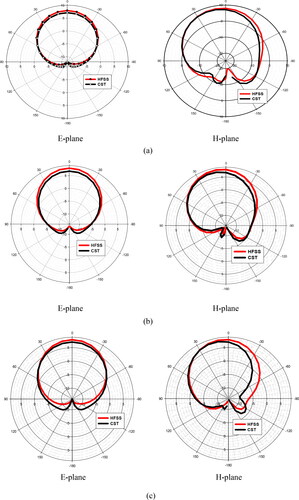
Figure 14. The antenna gain, directivity, and radiation efficiency vs frequency.
4.4. Surface current distribution
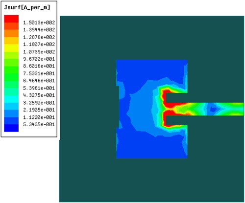
The surface current distribution at 28 GHz is displayed in . The current is concentrated along the feed line and at the edges of the inset feed gap, as can be noticed. The current density around the inset’s outer edges is 150.13 A/m. Along the feed line and around the inset from the inside, the current density is 107.39 A/m. We can also see that the current density around the slit’s edges and in the patch’s center is 21.9 A/m. Generally, current distribution along the radiating patch varies from 0.5 A/m to 150.13 A/m.
Figure 15. The surface current distribution at 28 GHz.
4.5. Comparison with some published works
compares this paper’s proposed antenna with several recently published works. S11 performance, antenna size, impedance bandwidth, gain, and radiation efficiency are all included in the comparison. Our proposed structure exceeds all antennas in (Farahat & Hussein, Citation2022; Paul & Saha, Citation2021; Przesmycki et al., Citation2020), and (Raheel et al., Citation2021) in terms of S11 performance, antenna gain, and radiation efficiency, according to the data in . Our design is likewise more compact than the antennas in (Hussain et al., Citation2022; Kamal et al., Citation2021; Paul & Saha, Citation2021; Rahman et al., Citation2016) and (Raheel et al., Citation2021). Despite having smaller dimensions and wider bandwidths than our work, the antennas in (Awan et al., Citation2021; Przesmycki et al., Citation2020) have lower gains and S11 at resonance. The designs in (Hussain et al., Citation2022; Kamal et al., Citation2021, Citation2021), and (Rahman et al., Citation2016) have broader bandwidths than our work, but they have lower radiation gains and larger dimensions. The antenna presented in (Paul & Saha, Citation2021) has a huge size of 40 × 30 mm2, although it possesses high gain and wide bandwidth. Regarding size, S11, radiation gain, and bandwidth, our work outperforms the antennas proposed in (Farahat & Hussein, Citation2022) and (Raheel et al., Citation2021). As a result, our proposed antenna outperforms all of the antennas in , as it is small, has a high gain, and has enough impedance bandwidth to cover the 28 GHz band (27.5 GHz – 28.35 GHz). Because of these outstanding characteristics, the antenna is suitable for 5 G smart phones.
Table 2. Comparison with some designs from the literature.
5. Conclusion
A compact rectangular microstrip patch antenna with a low profile and high gain is presented in this article. The proposed design is supplied by an inset feed line and uses the RT/Duroid 5880 substrate material. The proposed structure achieves a uniform gain above 8 dBi at the whole operating band. The proposed design also achieves an impedance bandwidth of 1.43 GHz, extending from 27.28 GHz to 28.71 GHz. The proposed antenna’s bandwidth is adequate to cover the 28 GHz as proposed by FCC (27.50 GHz – 28.35 GHz). At the resonance frequency, the antenna is well matched to its feed line, with a return loss of roughly 45 dB and a VSWR of 1.067. We regret that our country lacks the equipment needed to fabricate antennas and measure their characteristics, but we are hopeful that they will be accessible in the future. As an alternative, the CST electromagnetic simulator is used to check the validity of results obtained from the HFSS simulations and the findings show that they are quite similar. The suggested structure is a good candidate for the 28 GHz band applications due to its simplicity, good radiation properties, good radiation efficiency, and compactness. For future work, this proposed antenna element could be used to construct a MIMO antenna.
Disclosure statement
No potential conflict of interest was reported by the author(s).
Additional information
Notes on contributors
AbdulGuddoos S. A. Gaid
AbdulGuddoos S. A. Gaid obtained a B.Eng in Electronics Engineering from the Sudan University for Science and Technology (SUST), Khartoum, Sudan, in 2000. He pursued an M.Eng and a PhD in Electrical, Electronic, and Systems Engineering from Universiti Kebangsaan Malaysia (UKM) in 2004 and 2010, respectively. After joining Taylor’s University in September 2010, he served as a lecturer until August 2012. From September 2012 onward, Dr. Gaid has been a faculty member at the Communication and Computer Department, Faculty of Engineering, Taiz University. He teaches various courses in electrical, electronics, and communications. His primary research areas include wireless communications and microstrip patch antennas for wireless communication networks. Dr. Gaid has a publication record of over 30 conference and journal papers and has actively contributed to organizing committees for conferences such as the International Conference on Technology, Science, and Administration (ICTSA 2021) and the 3rd International Conference on Emerging Smart Technologies and Applications (eSmarTA 2023) held at Taiz University.
Mohammed A. M. Ali
Mohammed A. M. Ali graduated with a bachelor's degree in communication and computer engineering from the Faculty of Engineering and Information Technology at Taiz University in the academic year 2021/2022. Additionally, he possesses a diploma in Cisco networks. Eng. Ali has gained valuable expertise in the design of microstrip antennas for 5G wireless systems, contributing to three conference and journal papers. Currently, he serves as a site engineer in the wireless communication industry in Saudi Arabia.
Abdultawab Saif
Abdultawab Saif obtained a master's degree from the former Soviet Union at the Higher Institute of Communications in Moscow in 1991, specializing in Radio and Television Engineering. Later, in 2007, he completed his Ph.D. in Communications. He worked as an engineer at the television station of the Yemeni Arab Republic in the capital, Sana'a, since 1992. In the year 2000, he transitioned to the Yemeni Satellite Channel and remained there until 2004. After earning his Ph.D. in 2007, he joined the Department of Communications and Computer at the College of Engineering in Taiz University, where he continues to work to this day.
References
- Awan, W. A., Naqvi, S. I., Hussain Naqvi, A., Abbas, S. M., Zaidi, A., & Hussain, N. (2021). Design and characterization of wideband printed antenna based on DGS for 28 GHz 5G applications. Journal of Electromagnetic Engineering and Science, 21(3), 177–183. https://doi.org/10.26866/jees.2021.3.r.24
- Balanis, C. A. (2015). Antenna theory: Analysis and design. John Wiley & Sons.
- Banday, Y., Mohammad Rather, G., & Begh, G. R. (2019). Effect of atmospheric absorption on millimetre wave frequencies for 5G cellular networks. IET Communications, 13(3), 265–270. https://doi.org/10.1049/iet-com.2018.5044
- Dahlman, E., Mildh, G., Parkvall, S., Peisa, J., Sachs, J., Selén, Y., & Sköld, J. (2014). 5G wireless access: requirements and realization. IEEE Communications Magazine, 52(12), 42–47. https://doi.org/10.1109/MCOM.2014.6979985
- Diawuo, H. A., & Jung, Y.-B. (2018). Broadband proximity-coupled microstrip planar antenna array for 5G cellular applications. IEEE Antennas and Wireless Propagation Letters, 17(7), 1286–1290. https://doi.org/10.1109/LAWP.2018.2842242
- Farahat, A. E., & Hussein, K. F. A. (2022). Dual-Band (28/38 GHz) Wideband MIMO Antenna for 5G Mobile Applications. IEEE Access, 10, 32213–32223. https://doi.org/10.1109/ACCESS.2022.3160724
- Gad, N. H., & Vidmar, M. (2018). Design of a microstrip-fed printed-slot antenna using defected ground structures for multiband applications. The Applied Computational Electromagnetics Society Journal (ACES), 33(8), 854–860.
- Gaid, A. S. A., Alhakimi, A. M. H., Sae’ed, O. Y. A., Alasadee, M. S., & Ali, A. A. (2019a). Compact and bandwidth efficient multi-band microstrip patch antennas for 5G applications. In International conference of reliable information and communication technology (pp. 663–672). Springer.
- Gaid, A. S. A., Qaid, O. A. S., Ameer, M. A. A., Qaid, F. F. M., & AhMed, B. S. A. (2019b). Small and bandwidth efficient multi-band microstrip patch antennas for future 5G communications. In International conference of reliable information and communication technology (pp. 653–662). Springer.
- Gaid, A. S. A., Qasem, M. H. M., Sallam, A. A., & Shayea, E. Q. M. (2021). Dual-band rectangular microstrip patch antenna with CSRR for 28/38 GHz bands applications. In International conference of reliable information and communication technology (pp. 717–727). Springer.
- Gkonis, P. K., Trakadas, P. T., & Kaklamani, D. I. (2020). A comprehensive study on simulation techniques for 5g networks: State of the art results, analysis, and future challenges. Electronics, 9(3), 468. https://doi.org/10.3390/electronics9030468
- Hong, W., Jiang, Z. H., Yu, C., Hou, D., Wang, H., Guo, C., Hu, Y., Kuai, L., Yu, Y., Jiang, Z., Chen, Z., Chen, J., Yu, Z., Zhai, J., Zhang, N., Tian, L., Wu, F., Yang, G., Hao, Z.-C., & Zhou, J. Y. (2021). The role of millimeter-wave technologies in 5G/6G wireless communications. IEEE Journal of Microwaves, 1(1), 101–122. https://doi.org/10.1109/JMW.2020.3035541
- Hu, R., Lili, W., Yi, Q., & Geng, W. (2014). Key elements to enable millimeter wave communications for 5G wireless systems. IEEE Wireless Communications, 21(6), 136–143. https://doi.org/10.1109/MWC.2014.7000981
- Hussain, M., Mousa Ali, E., Jarchavi, S. M. R., Zaidi, A., Najam, A. I., Alotaibi, A. A., Althobaiti, A., & Ghoneim, S. S. M. (2022). Design and characterization of compact broadband antenna and its MIMO configuration for 28 GHz 5G applications. Electronics, 11(4), 523. https://doi.org/10.3390/electronics11040523
- Ismail, F. F., El-Aasser, M. A., & Gad, N. H. (2022). A parasitic hat for microstrip antenna design based on defected structures for multiband applications. The Applied Computational Electromagnetics Society Journal (ACES), 37(5), 568–575. https://doi.org/10.13052/2022.ACES.J.370506
- Kamal, M. M., Yang, S., Kiani, S. H., Anjum, M. R., Alibakhshikenari, M. o. h., Arain, Z. A., Jamali, A. A., Lalbakhsh, A., & Limiti, E. (2021). Donut-shaped mmwave printed antenna array for 5G technology. Electronics, 10(12), 1415. https://doi.org/10.3390/electronics10121415
- Kamal, M. M., Yang, S., Kiani, S. H., Sehrai, D. A., Alibakhshikenari, M., Abdullah, M., Falcone, F., Limiti, E., & Munir, M. (2021). A novel hook-shaped antenna operating at 28 GHz for future 5G mmwave applications. Electronics, 10(6), 673. https://doi.org/10.3390/electronics10060673
- Mitra, R. N., & Agrawal, D. P. (2015). 5G mobile technology: A survey. Ict Express, 1(3), 132–137. https://doi.org/10.1016/j.icte.2016.01.003
- Mohammed, A. S. B., Kamal, S., Bin Ain, M. F., Ahmad, Z. A., Zahar, Z., & Hussin, R. (2020). Improving the gain performance of 2 × 2 U-slot air substrate patch antenna array operated at 28 GHz wideband resonance for 5G application. IOP Conference Series: Materials Science and Engineering, 917(1), 012083. https://doi.org/10.1088/1757-899X/917/1/012083
- Mohammed, A. S. B., Kamal, S., Bin Ain, M. F., Hussin, R., Najmi, F., Sundi, S. A., Arifin Ahmad, Z., Ullah, U., Bin Mohamed Omar, M. F., & Othman, M. (2021). Mathematical model on the effects of conductor thickness on the centre frequency at 28 GHz for the performance of microstrip patch antenna using air substrate for 5G application. Alexandria Engineering Journal, 60(6), 5265–5273. https://doi.org/10.1016/j.aej.2021.04.050
- Nahas, M. (2022). A super high gain l-slotted microstrip patch antenna for 5G mobile systems operating at 26 and 28 GHz. Engineering, Technology & Applied Science Research, 12(1), 8053–8057. https://doi.org/10.48084/etasr.4657
- Paul, L. C., & Saha, H. K. (2021). A dual blade-shaped patch directional array antenna for 5G communication [Paper presentation]. 2021 international conference on electronics, communications and information technology (ICECIT), pp. 1–4. IEEE. https://doi.org/10.1109/ICECIT54077.2021.9641479
- Paul, L. C., & Saha, H. K. (2021). A high gain array antenna for 28 GHz upper 5G application [Paper presentation]. 2021 international conference on electronics, communications and information technology (ICECIT), pp. 1–4. IEEE. https://doi.org/10.1109/ICECIT54077.2021.9641442
- Paul, L. C., & Saha, H. K. (2021). A wideband microstrip line feed slotted patch antenna for 28 ghz 5g applications [Paper presentation]. 2021 International Conference on Electronics, Communications and Information Technology (ICECIT), pp. 1–4. IEEE. https://doi.org/10.1109/ICECIT54077.2021.9641230
- Paul, L. C., Ali, M. H., Sarker, N., Mahmud, M. Z., Azim, R., & Islam, M. T. (2021). A wideband rectangular microstrip patch antenna with partial ground plane for 5G applications [Paper presentation]. 2021 Joint 10th international conference on informatics, electronics & vision (ICIEV) and 2021 5th international conference on imaging, vision & pattern recognition (icIVPR), pp. 1–6. IEEE. https://doi.org/10.1109/ICIEVicIVPR52578.2021.9564160
- Paul, L. C., Das, S. C., Sarker, N., Azim, R., Ishraque, M. F., & Shezan, S. A. (2021). A wideband microstrip patch antenna with slotted ground plane for 5G application [Paper presentation]. 2021 international conference on science & contemporary technologies (ICSCT), pp. 1–5. IEEE. https://doi.org/10.1109/ICSCT53883.2021.9642597
- Paul, L. C., Das, S. C., Sarker, N., Ishraque, M. F., Azim, R., & Mahmud, M. Z. (2021). A low profile microstrip patch antenna with DGS for 5G application [Paper presentation].2021 International Conference on Science & Contemporary Technologies (ICSCT), pp. 1–5. IEEE. https://doi.org/10.1109/ICSCT53883.2021.9642644
- Paul, L. C., Saha, H. K., & Lee, W.-S. (2021). A Double T-shaped Wideband Microstrip Patch Antenna with a Modified Ground Plane for 5G Applications [Paper presentation]. 2021 IEEE Indian Conference on Antennas and Propagation (InCAP), pp. 790–793. IEEE. https://doi.org/10.1109/InCAP52216.2021.9726442
- Pirinen, P. (2014). A brief overview of 5G research activities [Paper presentation].1st International Conference on 5G for Ubiquitous Connectivity, pp. 17–22. IEEE. https://doi.org/10.4108/icst.5gu.2014.258061
- Przesmycki, R., Bugaj, M., & Nowosielski, L. (2020). Broadband microstrip antenna for 5G wireless systems operating at 28 GHz. Electronics, 10(1), 1. https://doi.org/10.3390/electronics10010001
- Raheel, K., Altaf, A., Waheed, A., Kiani, S. H., Sehrai, D. A., TuBBal, F., & Raad, R. (2021). E-shaped H-slotted dual band mmWave antenna for 5G technology. Electronics, 10(9), 1019. https://doi.org/10.3390/electronics10091019
- Rahman, A., Yi, N. M., Ahmed, A. U., Alam, T., Singh, M. J., & Islam, Moha. M. M. T. (2016). A compact 5G antenna printed on manganese zinc ferrite substrate material. IEICE Electronics Express, 13(11), 20160377–20160377. https://doi.org/10.1587/elex.13.20160377
- Rappaport, T. S., Sun, S., Mayzus, R., Zhao, H., Azar, Y., Wang, K., Wong, G. N., Schulz, J. K., Samimi, M., & Gutierrez, F. (2013). Millimeter wave mobile communications for 5G cellular: It will work!. IEEE Access.1, 335–349. https://doi.org/10.1109/ACCESS.2013.2260813
- Samimi, M., Wang, K., Azar, Y., Wong, G. N., Mayzus, R., Zhao, H., Schulz, J. K., Sun, S., Gutierrez, F., & Rappaport, T. S. (2013). 28 GHz angle of arrival and angle of departure analysis for outdoor cellular communications using steerable beam antennas in New York City [Paper presentation].2013 IEEE 77th Vehicular Technology Conference (VTC Spring), In pp. 1–6. IEEE. https://doi.org/10.1109/VTCSpring.2013.6691812
- Uwaechia, A. N., & Mahyuddin, N. M. (2020). A comprehensive survey on millimeter wave communications for fifth-generation wireless networks: Feasibility and challenges. IEEE Access, 8, 62367–62414. https://doi.org/10.1109/ACCESS.2020.2984204
- Wang, X., Kong, L., Kong, F., Qiu, F., Xia, M., Arnon, S., & Chen, G. (2018). Millimeter wave communication: A comprehensive survey. IEEE Communications Surveys & Tutorials, 20(3), 1616–1653. https://doi.org/10.1109/COMST.2018.2844322
- Yau, K.-L A., Qadir, J., Wu, C., Imran, M. A., & Ling, M. H. (2018). Cognition-inspired 5G cellular networks: A review and the road ahead. IEEE Access, 6, 35072–35090. https://doi.org/10.1109/ACCESS.2018.2849446
- Zikria, Y., Kim, S., Afzal, M., Wang, H., & Rehmani, M. (2018). 5G mobile services and scenarios: Challenges and solutions. Sustainability, 10(10), 3626. https://doi.org/10.3390/su10103626