Figures & data
Figure 1. Proposed system.
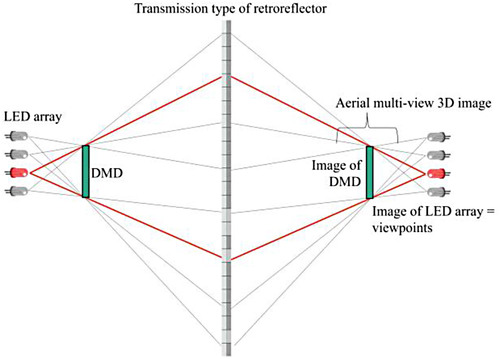
Figure 2. Comparison of image formation between the lens and transmission type retroreflector. (a) Image after the lens. (b) Image after the transmission type retroreflector.
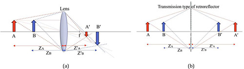
Figure 3. SMA structure.
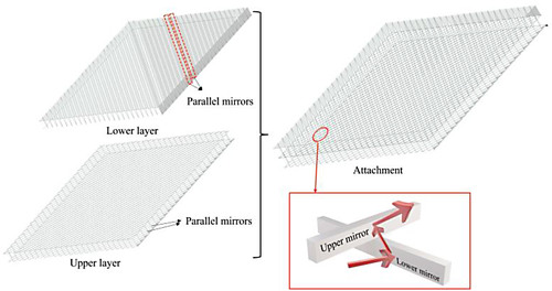
Figure 4. Different reflection types within two mirrors.
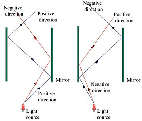
Figure 5. Ray tracing simulation of SMA. (a) 2D simulation of one mirror layer. (b) 3D simulation of both mirror layers.
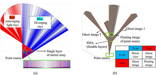
Figure 6. Detailed configuration of the proposed system.
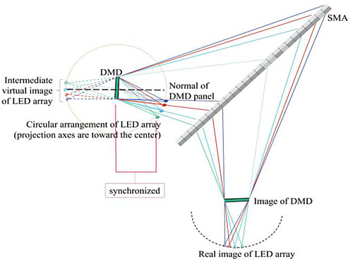
Figure 7. Intermediate virtual image of an LED formed by a single pixel mirror of DMD. (a) ON state mirror. (b) OFF state mirror. (c) Angular difference between ON and OFF state pixel mirror images.
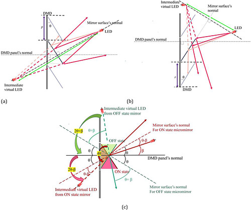
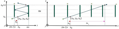
Figure 8. Calculation of the intermediate virtual LEDs’ position to determine the amount of blurriness. (a) ON state. (b) OFF state.
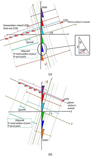
Figure 9. LED array projecting on DMD in both states. (a) ON state. (b) OFF state.
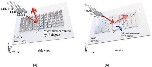
Figure 10. Viewpoints formation. (a) ON state. (b) OFF state.
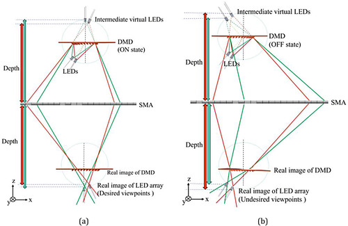
Figure 11. Experimental setup.
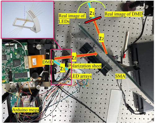
Figure 12. Time diagram for synchronization.

Figure 13. Experimental results. (a) Image of the DMD panel. (b) Desired and undesired viewpoint array with a faint image of the LED array in between. (c) The angular separation of desired and undesired viewpoint from a single LED.
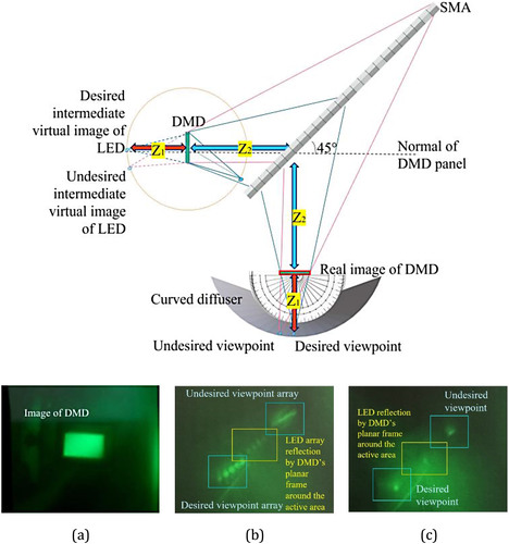
Figure 14. Experimental results.
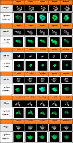
Figure 15. Simulation result: ratio of different reflection types.
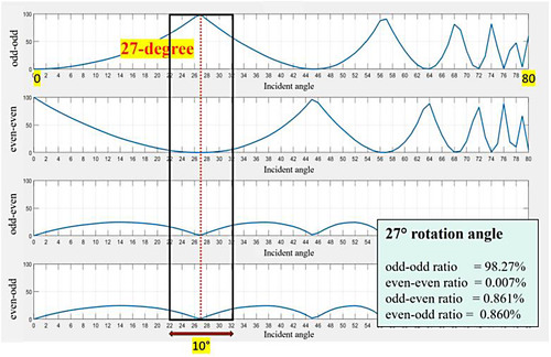
Figure 16. Experimental verification: ratio of different reflection types.
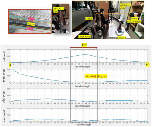
Figure 17. Image quality comparison between a lens and SMA.
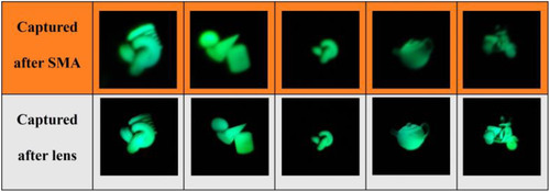
Figure 18. Comparison of the focused and blurry images. (a) Focused image. (b) Blurred image.

Figure 19. Non-desired diffraction orders are observed when the polarization sheet is not used.
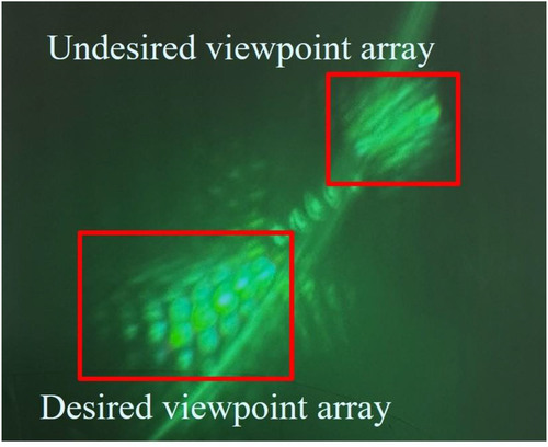
Figure 20. (a) Diffraction orders of the DMD. The strongest diffraction order in (b) ON state and (c) OFF state.
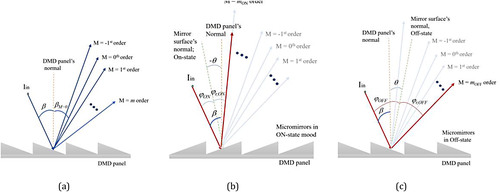
Figure 21. (a) Diffraction order distribution for two incident beams, (b) strongest diffraction orders for two beams in the ON-state mode.
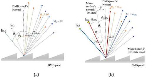
Figure A1. Positive direction, an odd number of reflections.