Figures & data
Figure 1 Target regions on the heart for suction bases. (A) Coronal view. The location of the skin incision for a subxiphoid approach is shown. (B) Sagittal view. The three target regions for the various suction bases are highlighted.
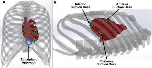
Figure 2 Design and prototype of the superior suction base. There are two superior suction bases, referred to as the anterior suction base and the posterior suction base. (A) Side view of the superior suction base, introducer arm, and TygonTM suction line. (B) Isometric view of the CAD model and prototyped model of the superior suction base, with the injector head drive wire passage highlighted. The model shown is the anterior suction base with the drive wire exiting from the suction base from the right. The posterior suction base will have a passage for the drive wire on the opposite side of that on the anterior suction base. (C) Top view of the superior suction base and TygonTM suction line. (D) Bottom view of the superior suction base and introducer arm. The injector head drive wire guide is highlighted, which directs the wire through the passage shown in (B), as well as the suction channel opening, which enables fixation of the suction base to its target region.
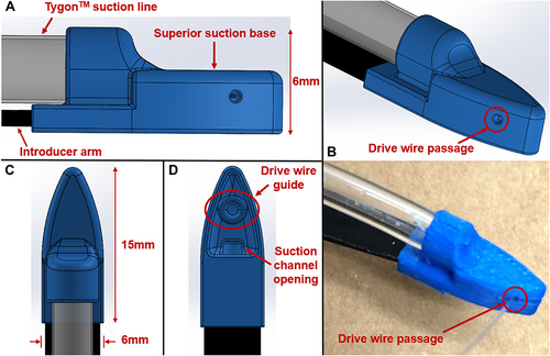
Figure 3 Design and prototype of the epicardial guide. The shape of the epicardial guide is designed to conform to the exterior surface of the heart. (A) Isometric view. The top opening allows for insertion of the superior suction base with the suction line and introducer arm attached. The bottom opening allows for the superior suction base to exit and continue on towards the target region on the heart, either anteriorly or posteriorly. The cover on opposite sides prevents premature exit of the superior suction base with an opening less than the width of the superior suction base introducer arm. (B) Side view. The epicardial guide handle is shown, controllable by the operator. (C) Top view. (D) and (E) Side and isometric views of the prototyped epicardial guide and handle.
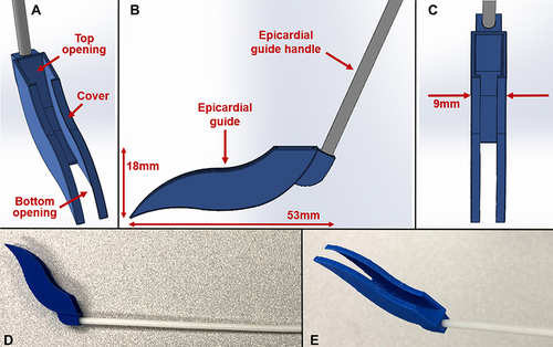
Figure 4 Prototype of the inferior suction base. The two suction lines from each superior suction base are directed through the inferior suction base. For the purposes of this study, suction is not required on the inferior suction base.
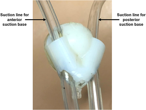
Figure 5 Testing model setup. (A) The rubber beating-heart was positioned anatomically and fixed in place. (B) Thorax with ribcage placed over the rubber heart. The subxiphoid approach access port was used for testing. (C and D) A nylon sock was placed snugly over the heart to replicate the pericardium. The target regions for the suction bases were labelled on the nylon sock with a marker.
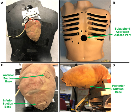
Figure 6 Two perpendicular cuts (2 cm, 1 cm) were made adjacent to each other on the pericardium near the apex of the heart to form a merged incision.
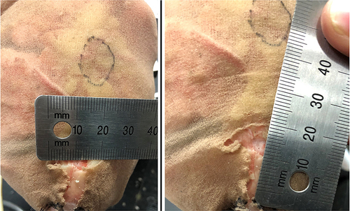
Figure 7 Prototype of HeartPrinter used for testing. The superior suction bases, introducer arms, suction lines, and inferior suction base are shown. The injector head which completes the HeartPrinter system is not shown.
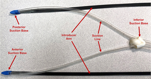
Figure 8 Introducer Mechanism I. The workflows in sequential order are depicted for positioning the: (A) anterior suction base; (B) posterior suction base; (C) inferior suction base.
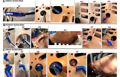
Figure 9 Introducer Mechanism II. This mechanism functions through the pushing tool, indicated in red, that directs the inferior suction base towards the apex of the heart. Cable lines, shown in green, which travel from the pushing tool to the introducer arms, passing through the drive wire passages on the superior suction bases, are pulled in order to propel the pushing tool forwards.
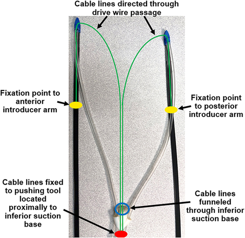
Figure 10 Setup of Introducer Mechanism II after removal of the epicardial guide and suction is activated at the superior suction bases. In order to improve visualization, the thorax is removed for this figure. (A) The introducer arms are still slotted into the superior suction bases, with a cable line fixed to each introducer arm, circled in green. The pushing tool located proximally to the inferior suction base is shown in red. The suction lines are fixed at the proximal end, which enables the pushing tool to direct the inferior suction base along the suction lines and towards the target region. (B) The introducer arms are pulled from their slots on the superior suction bases. The fixation points for the cable lines on the introducer arms are now visible, circled in yellow. These will continue to be retracted, thereby directing the pushing tool forwards.
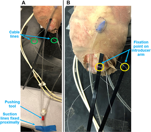
Figure 11 Process of positioning the inferior suction base near the apex of the heart. (A) The anterior and posterior cable lines are pulled in order to direct the pushing tool forwards, thereby propelling the inferior suction base towards its target region. (B) The cable lines continue to be pulled until the inferior suction base reaches the apex of the heart.
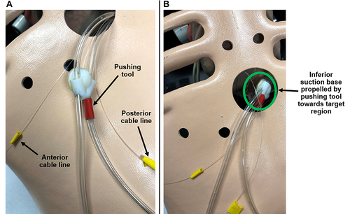
Figure 12 Set-up for epicardial guide insertion force measurements. A 3D printed coupler is used to connect the epicardial guide to the force gauge. (A) Insertion for anterior access to the heart. (B) Insertion for posterior access to the heart.
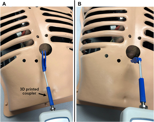
Figure 13 Captured images of successful positioning of the suction bases on the heart using Introducer Mechanism I. (A) Anterior suction base. (B) Posterior suction base. (C) Inferior suction base and posterior suction base. (D) Inferior suction base and anterior suction base. The thorax was removed for improved visualization. (E) All three suction bases positioned at their target regions, forming the triangular support structure.
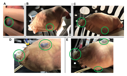
Figure 14 Captured image of successful positioning of the inferior suction base near the apex of the heart, using Introducer Mechanism II.
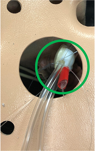
Table 1 Epicardial Guide Insertion and Suction Base Positioning Time Measurements Using Introducer Mechanism I
Table 2 Epicardial Guide Insertion and Suction Base Positioning Time Measurements Using Introducer Mechanism II
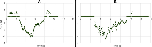
Figure 15 Sample plots of specific trials showing continuous force measurements experienced by the epicardial guide for (A) anterior access and (B) posterior access. Negative values correspond to compression forces which are of interest.