
 ?Mathematical formulae have been encoded as MathML and are displayed in this HTML version using MathJax in order to improve their display. Uncheck the box to turn MathJax off. This feature requires Javascript. Click on a formula to zoom.
Abstract
Solution-processed OLEDs offer a promising and affordable technology for solid-state lighting and superior self-luminous display panels. Herein, an imidazo[1,5-a]pyridine (ImPy)-based fluorophore decorated with an aromatic π-system anthracene is synthesized by a one-pot condensation approach. From the theoretical study, the energy difference between HOMO and LUMO is 3.1 eV. The molecule shows excellent thermal stability and electrochemical stability. It exhibits efficient intramolecular charge transfer and displays a positive solvatochromic photoluminescence emission band ranging from 528 nm in hexane to 586 nm in acetonitrile with large Stokes’ shift of ∼11,000 cm−1. The OLEDs made of this emitter displayed good device performance with luminous efficiency of 4.4 cd A–1, power efficiency of 2.2 lm W–1 and external quantum efficiency of 3.2%. Additionally, this OLED emitted greenish-yellow light with CIE coordinate (0.34, 0.45) and possessed a low turn-on voltage of 7 V. The material also used in white LED fabrication and the fabricated white LED displayed an excellent color rendering index (CRI), the luminous efficiency of radiation (LER), and correlated color temperatures (CCT) of 89328 lm W–1 , and 4907 K, respectively with CIE coordinate (0.35,0.32).
1. Introduction
During the past two decades, there has been a large advancement in the field of organic electronic devices due to their widespread applications with novel functionalities.[Citation1–4] Due to their simple and inexpensive synthesis processes, and efficient charge transfer characteristics, the most alluring optoelectronic devices are made of π-conjugated organic materials. Organic optoelectronic devices are the most intriguing contenders for the constantly changing technological demand along with environmental safety. From Tang and VanSlyke’s pioneering research on organic light-emitting diodes (OLEDs) in 1987, great attention from both academia and industries has been devoted to analyzing and fabricating OLEDs because of their reliability, effectiveness, and chromatic adaptability toward futuristic uses in flat panels and lighting environments.[Citation5–7] It received significant attention because of the enormous possibilities to be employed as backlighting resources for fluid crystal, flat-panel screens, solid-state light, and white OLEDs (WOLEDs).[Citation8–10] The advancement in the synthesis and application of three main color red, green, and blue luminescent materials has received much interest in pursuing superior wide-color spectrum panels.[Citation11, Citation12] Yellow emission is also significant besides the three fundamental colors.[Citation13] Yellow emission is necessary for RGBY-TVs, lithography laboratories, and traffic signal lights and may assist in achieving white OLEDs for high CRI for solid-state illumination.[Citation14] It does not harm the retina of the eye while improving the CRI of white OLEDs while used in solid-state lighting. Furthermore, communication systems and companies that prepare light-sensitive materials often employ monochromatic yellow light.[Citation15] However, there are only a few effective materials which emit pure yellow light. Thus, obtaining yellow emission in superior quality can be challenging because of the very constrained area of the yellow-light chromaticity in the Commission International de L'Eclairage (CIE) graphic. Since yellow light-emitting layers often provide low turn-on voltages and utilize less power without compromising brightness efficiency, longevity, or color purity in the devices, there is a continuing need for research and development into these layers. In the past two decades, the effective manufacture of OLED devices has been accomplished using the vacuum deposition approach.[Citation16] Their development is nevertheless restricted by difficult production procedures including extreme vacuum and high temperatures, and also expensive.[Citation17] Despite current advances, employing the vacuum deposition method to produce flat panel devices and device flexibility is still challenging. Gustafsson et al. created the initial adjustable OLED in 1992, utilizing a solution-processed method to overcome these problems.[Citation18] In contrast with the vacuum-evaporated OLEDs, one fascinating and economical technique that could be employed in premium solid-state sources of illumination and translucent screens is solution-processed OLEDs (s-OLEDs) due to the versatility in producing large-scale.[Citation10, Citation19, Citation20] LEDs are frequently employed in lighting sources, display technology, and visible light communication (VLC).[Citation21–23] As compared to incandescent and fluorescent lighting, the Gallium Nitride (GAN)-based LED is an efficient light source because of its low operational voltage, ability to operate in cold conditions, no heat emission, energy efficiency, eco-friendly, and long life span.[Citation24–26] In general, two contrasting colors (blue and yellow or greenish yellow) or three main colors (red, green, and blue) can be used to produce white light emission. Due to the absence of proper mixing of the three primary constituents in the white LED spectrum, conventional white LEDs have extremely low CRI and CCT.[Citation27] Efficient blue and yellow emitters with high luminosity efficiencies must be developed to further enhance the efficiency of white LED. One important route for making white LEDs is a hybrid inorganic/organic LED design, in which a blue emissive GAN-based LED is coated with a yellow organic compound and a red-emitting material with an absorbance band that is parallel to the inorganic LED structure's emission wavelength.[Citation28, Citation29] Some of the high-energy blue photons generated by the inorganic LEDs are converted into lower-energy yellowish-red light by mixing organic phosphor with the inorganic LEDs. The combination of blue, red, and yellow colors in a proper ratio can give high-quality white light. [Citation30]
For the fabrication of OLEDs, imidazole-based fluorophores are gaining wide interest due to their efficient charge transfer nature, its sp2 hybridized nitrogen atom of imidazole makes it electron-withdrawing in nature and two lone pairs of electrons make it electron-donating by nature.[Citation31] Due to the appropriate Lowest Unoccupied Molecular Orbital (LUMO) energy level of [1,5-a]IP, it can ease the electron injection in OLED devices.[Citation31] Anthracene is well known for its superior luminescence capability and efficient charge transfer ability when appended with other electron donors or acceptor moieties.[Citation32] Owing to its excellent fluorescence quantum efficiency and wide band gap in solution, anthracene derivatives are now recognized as an appealing fundamental component and base substance for OLEDs.[Citation33]
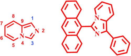
Therefore, in this work effort has been made to investigate the photophysical characteristics, OLED performance, and fabrication of white LED of an imidazo-anthacene-based yellow fluorophore by condensing the imidazo[1,5-a]pyridine (ImPy) as the basic component with phenyl and anthracene at the C1, C3 positions, respectively of the ImPy, as shown in Figure . The imidazole unit's electron-donating characteristics, coupled with the extended conjugation inherent in the anthracene unit, can facilitate intramolecular charge transfer (ICT) processes, and thereby impact the collective photophysical behavior. The extension of conjugation typically induces a red shift in both absorption and emission spectra. Anthracene's fluorescence attributes exhibit sensitivity to the surrounding environment's polarity, with alterations in solvent polarity potentially causing shifts in both emission wavelength and intensity. Aggregation due to π-π stacking interactions in the solid state or concentrated solutions leads to a redshift in emission and absorption spectra. When a molecule incorporates both imidazole and anthracene units, their combined influence generates synergistic effects on photophysical properties. Specifically, the interaction between imidazole and anthracene moieties can intricately modulate the overall electronic structure and emission characteristics.[Citation34–36] Chemical structure of the generated molecule has been characterized by employing several characterization tools, such as NMR, HRMS, and SCXRD. Quantum chemical calculations, photophysical analyses such as UV-Vis, photoluminescence (PL), solvatochromism, thermal analyses such as thermogravimetry analysis (TGA), differential scanning calorimetry (DSC), and cyclic voltammetry (CV) studies of ImPy-Ac have been conducted to verify its suitability as OLEDs and white LED.
Figure 1. Chemical structure of the synthesized fluorophore.
2. Results and discussion
2.1. Theoretical calculation
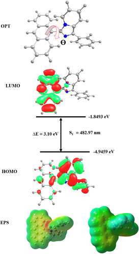
To acquire greater knowledge about the geometry and electronic properties of the fluorophore, accountable for fluorescence characteristics, a theoretical study was carried out in both gas and solvent phases using density functional theory (DFT) with B3LYP/6-31G (d, p) basis set.[Citation37, Citation38] The optimized geometry, HOMO/LUMO energy levels, and electrostatic potential (ESP) are shown in Figure . The optimized structure shows a rigid conformation that can successfully avoid the clustering of particles in the solid state, and minimize energy loss through the non-radiative transition and aggregation-caused quenching by preventing intramolecular interaction.[Citation39, Citation40] From the optimized geometry the dihedral angle (θ) between the anthracene unit and the imidazole unit is 62° and it indicates that the molecule is non-coplanar with a twisted structure. The highest occupied molecular orbital (HOMO) is mainly distributed in the electron-donating imidazole unit and the pyridine moiety. The LUMO is found on the electron-accepting anthracene ring. The HOMO and LUMO energy levels are −4.94 eV and −1.84 eV, respectively. The band gap (Eg) is 3 eV and it is well matched with the experimental CV data. An ESP map was also used to study the distribution of ground-state electronic clouds. The most negative potential (red cloud) is found in the electron-deficient nitrogen atom (–N = ) of the pyridine ring and the positive potential (blue cloud) is detected in anthracene and the pyrrole-type nitrogen ring. The green and yellow region of the compound in the ESP map is the neutral electrostatic potential. The atom coordinates and vertical transitions are given in the supplementary information (Table ST5 and ST6). By using time-dependent DFT (TD-DFT), the UV-Vis spectra of the fluorophore have been obtained. The simulated absorption spectra of the fluorophore in the gas phase and THF phase are displayed in Fig. S6. The molecule shows two absorption bands in simulated UV-Vis spectra in both the gas phase and the THF phase. The absorption band near 300 nm corresponds to the π-π* transition in the aromatic imidazole moiety, and the band above 300 nm is due to the intramolecular charge transfer transition. The theoretical finding is well agreed with the experimental test. From TD-DFT the S1 and T1 energy levels are 2.567 and 0.776 eV and their difference (ΔEST) is 1.791 eV. The ground state dipole moment was estimated from the optimized structure that is 3.29 D. To know more about the transition in the excited state natural transition orbitals (NTO) calculations were conducted for the first 8 singlet and triplet excited states with particle-hole pair contribution which is presented in Fig. S4..[Citation41] From the S0 →S1 transition the hole is localized in the imidazole pyridine unit and the phenyl ring whereas the particle or electron was found in the anthracene unit. In this transition, the charges are partly localized in different units of the molecule, so this shows the charge transfer (CT) state. In the case of the S0 →S2 transition both the hole and particles are concentrated in the anthracene ring; this shows the locally excited state (LE). The S4 and S3 states are mixed states, both LE and CT states.
Figure 2. Optimized molecular geometry, HOMO/LUMO energy levels, and electrostatic potential map of ImPy-Ac.
2.2. Synthesis of 3-(anthracene-9-yl)-1-phenylimidazo[1,5-a]pyridine
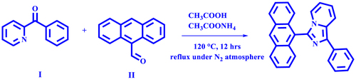
The synthesis of ImPy-Ac was carried out followed by the previously reported method.[Citation42] The combination of phenyl(pyridin-2-yl)methanone (500 mg, 2.73 mmol, 1 equivalent) (I), Anthracene-9-carbaldehyde (468.5 mg, 3 mmol, 1.1 equivalent) (II) and ammonium acetate (983.9 mg, 13.4 mmol, 5 equivalent) was stirred at 120 °C in glacial acetic acid (20 ml) in a round bottom flask with a reflux condenser in an inert environment (Scheme 1). Termination of the reaction has been monitored by thin-layer chromatography. The reaction mixture was transferred to cold water after 12 h and neutralized by liquor ammonia, then the compounds were extracted using dichloromethane. The organic phase was extracted and dried using anhydrous sodium sulfate and the solvent was evaporated using a rotary evaporator. The resulting material was purified utilizing silica gel column chromatography with a mixture of ethyl acetate and petroleum ether as the eluent (ethylacetate/pet ether 1:19). Yellow crystalline solid was extracted (yield = 30.13%) and characterized by 1H NMR (Fig. S1), 13C NMR (Fig. S2) and HRMS (Fig. S3). 1H NMR (400 MHz, CDCl3) δ 8.69 (s, 1H), 8.13 (d, J = 8.1 Hz, 4H), 8.05 (d, J = 9.4 Hz, 1H), 7.55 (t, J = 9.5 Hz, 7H), 7.44 (t, J = 7.6 Hz, 2H), 7.36 (t, J = 7.5 Hz, 1H), 7.19 (d, J = 7.2 Hz, 1H), 6.89 (t, J = 7.9 Hz, 1H), 6.44 (t, J = 6.8 Hz, 1H). 13C NMR (100 MHz, CDCl3) δ 137.11, 135.23, 135.17, 132.98, 131.92, 131.53, 131.02, 129.59, 128.81, 128.21, 127.10, 127.02, 126.74, 126.51, 125.69, 125.57, 124.68, 123.02, 122.27, 119.99, 119.04, 112.96. MS (m/z): 370.147 for C27H18N2, 371.147 for [M + H].
Scheme 1. Synthetic route of ImPy-Ac.
2.3. Thermal properties
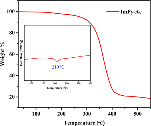
For the fabrication of OLED devices, thermal durability is a crucial factor.[Citation43] TGA and DSC were performed in a nitrogen environment to look at the thermal properties of the compound.[Citation44] DSC-TGA observations from 30 °C to 600 °C were performed at a scanning rate of 10 °C min–1. The produced emitter's DSC-TGA profiles are shown in Figure . The developed emitter has a considerably high melting point (Tm = 210 °C) matched with melting point temperature and no glass transition temperature was found as per the DSC profile. It also shows a very high thermal decomposition temperature (Td) (5% weight loss of initial weight) of approximately 271 °C which is confirmed by TGA analysis.
Figure 3. TGA curve and DSC curve under the N2 atmosphere of the fluorophore.
2.4. Crystal structure
The crystal structure of ImPy-Ac is verified through SCXRD and the compound is crystallized in a monoclinic structure. The molecules’ ORTEP diagram is shown in Figure , the crystallographic data are given in Table ST3, and the relevant bonding information is provided in Tables ST1 and ST2. CIF files of the structures have been deposited on the CCDC database with codes 2,297,482.
Figure 4. ORTEP diagram of the ImPy-Ac.
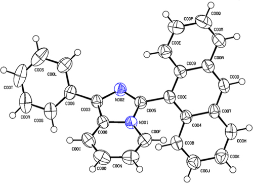
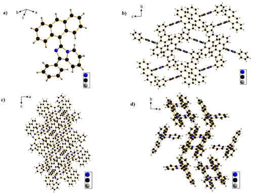
Single molecular geometry and molecular packings of the ImPy-Ac are revealed in Figure . From a single crystal structure, it was confirmed that ImPy-Ac has twisted geometry with a twisting angle (dihedral angle, N001-C005-C00C-C004, ω) of 62.58° between anthracene and imidazole ring and this well agreed with the theoretical study. The twisting nature of ImPy-Ac will suppress the formation of excimer in the OLED device and decrease the non-radiative transition. Moreover, molecular packings (Figure (b, c, and d)) suggest there are no π-π stacking and also negligible intermolecular interactions among the neighboring molecules. This suggests that OLED based on ImPy-Ac will be benefitted from aggregation-caused quenching at a high concentration which will help in suppressing non-radiative quenching (such as triplet–triplet annihilation (TTA) or triplet-polaron annihilation) and improving the device performance.[Citation45, Citation46]
Figure 5. Single molecular geometry (a) and molecular packings with the views from X-axis (b), Y-axis (c), and Z-axis (d) of ImPy-Ac crystal.
2.5. Optical properties
For a better understanding of fluorophores; photophysical characteristics, UV-Vis and PL spectroscopy were employed by using a 10–5 M solution of ImPy-Ac in THF and solid form. The UV-Vis spectrum presented in Figure and Table summarizes the pertinent information. The UV spectra in THF show two absorption peaks, the low wavelength and high energy absorption band below 270 nm may be due to π-π* transition in the anthracene and imidazole aromatic ring.[Citation47] The high wavelength low energy absorption peak above 300 nm is attributed to intramolecular charge distribution from anthracene to the imidazole unit. The optical band gap of the molecule is determined by diffuse reflectance spectra (DRS) using the Kubelka–Munk function.[Citation48] The optical band gap of the compound is 3.206 eV which is well agreed with the theoretical calculation. The PL spectra in Figure show greenish-yellow emission maxima at 548 nm in the THF solution. But in the case of thin film and solid PL spectra, a small red shift was observed due to aggregation form in a solid state.[Citation49] The excitation spectra of the solid state have been depicted in Fig. S5b. The S1 energy level from the onset value of the fluorescent spectrum is 2.5 eV. Phosphorescence spectrum (77 K PL spectra) was also measured to estimate the triplet energy level as displayed in Fig. S5f and the triplet energy level from the onset value of the spectrum is 2.3 eV. Photoluminescence quantum yield (PLQY) is an essential component for OLED, thus it is measured by integrating sphere and 74.6% (Fig. S5c).
Figure 6. UV-vis spectra in dilute THF solution (10−5 M) (b) Diffuse reflectance spectra (DRS) measured using a solid compound.
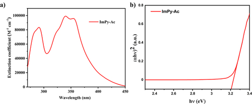
Figure 7. PL spectra of (a) ImPy-Ac solution in THF (10−5 M), (b) solid ImPy-Ac (c) Thinfilm.
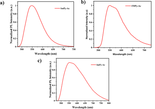
Table 1. Photophysical properties of ImPy-Ac.
2.6. Fluorescence lifetime
The fluorescence lifetime was examined for a deeper comprehension of the properties of the compound in their excited states. Time-correlated single photon counting (TCSPC) was utilized to evaluate the decaying of excitation of the fluorophores using the proper laser diodes by matching with the emission maximum.[Citation50] Fig S5d shows the decay curve and Table represents the information on fluorescence lifetime. Using equation (1), the lifespan of the produced luminophore was determined.
(1)
(1) where I0 is the offset value (I0 = 0), A1 is the scalar quantity acquired from the curve fitting, t is the time in ns, and τ is the exponential decay time. The lifespan of the fluorophore was 2.31 ns.
Table 2. Electrochemical properties of ImPy-Ac.
2.7. Solvatochromism
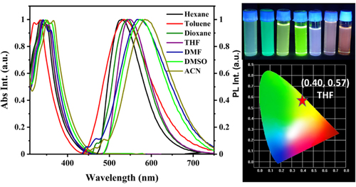
Solvatochromic using various solvents was also carried out to comprehend how molecules interact with solvents in the ground and excited states to investigate the intramolecular charge transfer by changing the solvent from non-polar to polar solvent. The spectra of emission and absorption in different solvents are presented in Figure and the excitation spectra are presented in Fig. S5a. The absorption spectra show a small bathochromic shift by changing the solvent from nonpolar to polar but a large bathochromic shift in the PL spectra from nonpolar to polar solvent was observed. It indicates a positive solvatochromism, i.e. ICT occurs in the excited state of the molecule. PL spectra shifted to a longer wavelength, a redshift of nearly 58 nm from low polarity solvent hexane to high polarity solvent acetonitrile (ACN). PL emission peaks widened and the full-width half maxima (FWHM) also increased, which clearly explained the CT excited states of the compound. Emission spectra shifted to longer wavelengths in high polar solvents due to (a) structural rearrangement in the excited state and (b) stabilization in polar solvents due to photo-induced ICT.[Citation51, Citation52] The observed weak emission between 450 nm–500 nm in the presence of highly polar solvents may be attributed to distinct molecular interactions or the formation of aggregates within the solvent medium.[Citation53, Citation54] Furthermore, a gradual increase in Stokes’ shift was found with an increasing solvent polarity which can be correlated with the Lipert-Mataga plot. The Lippert-Mataga plot, which describes the connection seen between solvents and dipole moments of the solute in the ground state (S0) and the lowest excited state (S1), is shown in Fig S5e.[Citation55] The Lippert-Mataga plot shows Stokes’ shift vs orientation polarizability (Δf) of the compound in different solvents.[Citation56] According to Fig S5e, orientation polarizability (Δf) and Stokes’ shift have a direct proportionality or straight-line relationship. It is also seen that the stokes shift of the compound has a strong correlation with the Lippert Mataga parameter with an R2 value of 0.97 and slope of 1447. The excited state dipole moment was calculated from the Lippert-Mataga plot by taking the earlier reported equation and found to be 12.2 D.[Citation57–59] The corresponding data are noted in Table ST4.
Figure 8. Absorption and emission spectra of ImPy-Ac in different solvents and CIE coordinates.
2.8. Electrochemical properties
The CV study was carried out by employing 0.1 M tetrabutylammonium perchlorate (Bu4NClO4) as an electrolyte support in DMF solvent with a scanning rate of 100 mV s–1. Figure depicts the CV study and Table provides an overview of the relevant electrochemical data. This demonstrates the different oxidation and reduction activities of the emitter, and this demonstrates its ability to transport a bipolar carrier. Using de Leeuw et al.'s equations (2) and (3), we determined the HOMO and LUMO energy levels based on the onset potentials.[Citation60]
(2)
(2)
(3)
(3)
Figure 9. Cyclic voltammograms of ImPy-Ac.
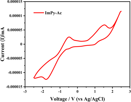
Table 3. Electroluminescent performance of ImPy-Ac.
From the above calculation, HOMO and LUMO are −5.02 and −3.59 eV, respectively, with a 1.43 eV electrochemical band gap between the two energy levels.
2.9. Fabrication of white LED
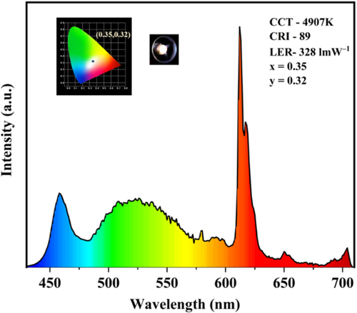
Utilizing the compounds’ greenish yellow emission, it was employed as organic phosphors for a white LED (LED coating) commercial application. By combining with an appropriate mass ratio of a previously reported red organometallic phosphor (Eu(II) complex) by our group and the yellow compound ImPy-Ac with a blue LED chip, a white LED was manufactured.[Citation29] The 1:2 mixture of synthesized fluorophore, the red phosphor was mixed with PMMA polymer, and coated on a commercial In-based blue LED chip for the fabrication of white LED. The EL spectra of the fabricated white LED are shown in Figure . The spectra show a warm white light emission with CRI value 89, CCT 4907 K, LER of 328 lm W–1, and CIE coordinate of (0.35,0.32) which is nearly matched with the NTSC standard value of white light emission.
Figure 10. EL spectra and CIE Coordinate of fabricated white LED.
2.10. Electroluminescence:
The electroluminescent characteristic of the fluorophore ImPy-Ac was examined by constructing s-OLED having the subsequent device configuration, ITO (150 nm)/PEDOT: PSS(30 nm)/CBP: Emitter X wt% (20 nm)/TPBi (30 nm)/LiF(1 nm)/Al (150 nm), with the emitter concentration (1,3,5 and 100 wt%). Figure shows graphical representations of the device construction and the matching energy level diagram. The host material, 4,4′-bis-(N-carbazolyl)−1,1′-biphenyl (CBP), the hole-injection layer (HIL), and the electron-transporting/hole-blocking layer (ETL/HBL) were all included in the device. Poly-(3,4-ethylenedioxythio-phene)-poly-(styrenesulfonate) or PEDOT:PSS acted as the HIL. Aluminum (Al) and lithium fluoride (LiF) were used for the cathode and electron-injection layer, correspondingly. Figures and provide an overview of OLED electroluminescent capabilities, and Table lists electroluminescence data. The electroluminescent bands of ImPy-Ac OLED are shown in Figure . Lower concentration (1, 3, and 5 wt%)-doped devices in CBP (host) produced greenish-yellow illumination and reached their maximal EL values at nearly 524 nm.
Figure 11. Schematic diagram of ImPy-Ac-based yellow OLED with energy level diagram and chemical structure of materials used.
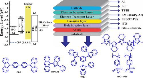
Figure 12. (a) current density vs voltage (b) luminescence vs voltage (V) (c) current efficiency (cd A–1) vs luminescence (cd m–2) (d) Power efficiency (lm W–1) vs luminescence (cd m–2).
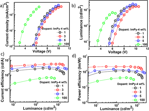
Figure 13. Electroluminescence spectra of ImPy-Ac.
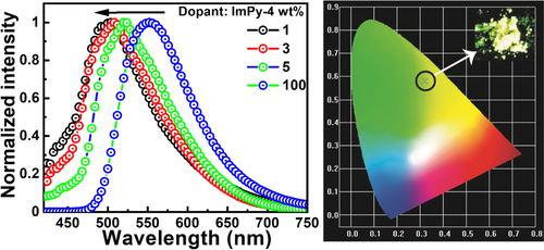
The doped OLED's emission nearly matched with the emitter's thin film and solution PL emission spectra while the solid PL spectra did not well match with EL emission which can be atrributed to the aggregate formation in the solid state, exciton formation, and dopant effects in the OLED device.[Citation16, Citation61] At a lower ratio (3 wt%), the produced excitons are successfully transported to the emitter. A noticeable reduction in host emission is seen when the emitter concentration is increased from 1 to 5 wt%. Whereas an OLED device having 100% of the emitters (neat without a host) displays a red-shifted greenish-yellow emission peak at 552 nm. The quenching is caused by aggregation (ACQ), which denotes the lower emission yield and the bathochromic shift in the emission.[Citation62]
The current efficiency (CE), power efficiency (PE), and electroluminescence (EL) spectra of ImPy-Ac OLEDs are shown in Figure , which show that they follow the pattern of decreased efficiency with low luminescence in the case of non-doped (100 wt% emitters) devices. A large current density is observed for the device with a complete emitter (100%), suggesting a substantial buildup and performance declines as a consequence of charge unbalance (Figure (a)). Among all these, the 3 wt% doped devices showed the maximum external quantum efficiency of 3.2%, power efficiency of 2.2 lm W–1, the current efficiency of 4.9 cd A–1, with CIE coordinate (0.34, 0.45) with turn-on voltage 7 V, and a luminescence of 1856 cd m–2. The device can act as an appropriate charge carrier for both holes and electrons. This might be caused by comparatively minimal obstacles for hole and electron injection from the HTL and EIL, respectively, into the active layer.
3. Conclusion
An imidazo[1,5-a]pyridine (ImPy)-anthacene-based fluorophore was developed for potential application in the fabrication of yellow OLED and white LED. From the theoretical study, it is found that the molecule shows appropriate HOMO–LUMO separation and the band gap is 3.1 eV. The thermally stable fluorophore shows greenish-yellow emission in both solution and solid-state having CIE coordinate (0.34, 0.45) with a positive solvatochromism and efficient ICT. The luminophore has been employed as a dopant in the fabrication of both doped and non-doped in solution-processed multilayer OLED devices. The electroluminescence efficiency of the doped devices is superior to that of the non-doped devices. The 3 wt% doped device shows a maximum EQE of 3.2%, PE of 2.2 lm W–1, the current efficiency of 4.4 cd A–1 with maximum luminescence of 1856 cd m–2 at an ELmax of 524 nm. Additionally, the fluorophore is used in the fabrication of white LED exhibiting excellent LER, CRI, and CCT of 328 lm W–1, 89m and 4907 K respectively with CIE coordinates (0.35,0.32) close to NTSC standard value for white color.
Supplemental Material
Download MS Word (1.6 MB)Disclosure statement
No potential conflict of interest was reported by the author(s).
Additional information
Funding
Notes on contributors

Bhabana Priyadarshini Debata
Bhabana Priyadarshini Debata is a Ph.D. research scholar under the guidance of Prof. Sivakumar Vaidyanathan and Prof. Sabita Patel at the Department of Chemistry of NIT Rourkela. She received her M.Sc. degree from Sambalpur University. She has been researching the design and synthesis of small molecules based on blue organic fluorophores, their experimental and theoretical properties, and their OLED/white LED applications.

Jwo-Huei Jou
Jwo-Huei Jou has been a Professor at the Department of Materials Science and Engineering of the National Tsinghua University in Taiwan since 1992. He received his Ph.D. degree in Macromolecular Science and Engineering from the University of Michigan in the U.S.A. in 1986. Until 1988, he worked as a visiting scientist at IBM Almaden Research. He has been granted and has filed more than 99 OLED-related patents [in the U.S.A., Republic of China (ROC), Japan, Korea, and Canada], published 230 OLED-related journal papers, and written 3 textbooks and 16 book chapters and magazine articles. His main research interests include high-efficiency and circadian rhythm-friendly OLEDs, polymers, thin film stress, and expert system applications.

Sabita Patel
Dr. Sabita Patel received her Bachelor’s (1997) from the Goverment College Sundargarh (affiliated to Sambalpur University) and Master’s (1999) from Sambalpur University, Jyoti Vihar. After the completion ofher M.Phil degree in 2000 from Sambalpur University in Organic synthesis and Micellar Chemistry, she joined the research group of Prof. B. K. Mishra as a CSIR NET (JRF) Fellow for Ph.D. programme in Physical-Organic chemistry. She then moved to Dong-A University, Busan, South Korea for her postdoctoral research with Prof D. D. Sung (March 2008 to June2008). She joined NIT Rourkela as a lecturer in chemistry in 2008. Her research interest includes Physical Organic Chemistry, Functional surfactants for organic reactions drug delivery, and synthesis and application of functional chromophores/fluorophores. Recently, she has been engaged in the synthesis of donor–acceptor fluorophores (including AIE active molecule) for organic electronics.

Sivakumar Vaidyanathan
Sivakumar Vaidyanathan received his Bachelor’s (2000) and Master’s (2002) degrees in Chemistry from Muthurangam Government Arts College, Vellore (affiliated to the University of Madras) and his PhD in Solid-State Chemistry (2007) from the Indian Institute of Technology, Madras, with Prof. U. V. Varadaraju. Then, he moved to Prof. Duk Young Jeon’s group at the Korea Advanced Institute of Science and Technology, Republic of Korea, as a Brain Korea 21 postdoctoral research fellow (2007–2009). He also worked as a postdoctoral fellow at the Commissariat a` l’Energie Atomique (CEA), Saclay, France, for a year. After spending a decade at NIT Rourkela as a faculty member in the Department of Chemistry, he moved to the Department of Chemistry at the Indian Institute of Technology Hyderabad. His research focuses on lanthanide photochemistry and photophysics, molecular materials for OLEDs, Pure organic room temperature materials, phosphors for LEDs (solid-state lighting), and organic fluorophores for diverse applications.
References
- K.R. Naveen, J.H. Oh, H.S. Lee, and J.H. Kwon, Angew. Chemie Int. Ed 62 (32), e202306768 (2023).
- J. Zhang, Q. Wei, W. Li, H. Chen, X. Zhu, Y. Bai, N. Fei, L. Cao, Z. Zhao, A. Qin, B.Z. Tang, and Z. Ge, Aggregate 00, e410 (2023). https://doi.org/10.1002/agt2.410
- M.-J. Tsai, W.-L. Huang, L.-M. Chen, G.-L. Ruan, D. Luo, Z.-L. Tseng, and K.-T. Wong, J. Mater. Chem. C 11 (3), 1056–1066 (2023).
- M. Wang, D. Luo, T.-H. Yeh, Y.-H. Huang, C.-L. Ko, W.-Y. Hung, Y. Tang, S.-W. Liu, K.-T. Wong, and B. Hu, Adv. Opt. Mater 11 (8), 2202477 (2023).
- C.W. Tang, and S.A. Vanslyke, Appl. Phys. Lett 51 (12), 913–915 (1987).
- M.A. Baldo, S. Lamansky, P.E. Burrows, M.E. Thompson, and S.R. Forrest, Appl. Phys. Lett 75 (1), 4–6 (1999).
- S.R. Forrest, and M.E. Thompson, Chem. Rev 107 (4), 923–925 (2007).
- K.S. Yook, and J.Y. Lee, Adv. Mater 26 (25), 4218–4233 (2014).
- Y.J. Cho, S.K. Jeon, S.-S. Lee, E. Yu, and J.Y. Lee, Chem. Mater 28 (15), 5400–5405 (2016).
- L. Ying, C.-L. Ho, H. Wu, Y. Cao, and W.-Y. Wong, Adv. Mater 26 (16), 2459–2473 (2014).
- G. Gustafsson, Y. Cao, G.M. Treacy, F. Klavetter, N. Colaneri, and A.J. Heeger, Nature 357 (6378), 477–479 (1992).
- M.C. Gather, A. Köhnen, and K. Meerholz, Adv. Mater 23 (2), 233–248 (2011).
- C.-C. Wu, Y.-T. Lin, K.-T. Wong, R.-T. Chen, and Y.-Y. Chien, Adv. Mater 16 (1), 61–65 (2004).
- J.-H. Jou, S.-C. Fu, C.-C. An, J.-J. Shyue, C.-L. Chin, and Z.-K. He, J. Mater. Chem. C 5 (22), 5478–5486 (2017).
- Z. Ahmed, and K. Iftikhar, Inorg. Chem 54 (23), 11209–11225 (2015).
- C.-L. Wu, C.-H. Chang, Y.-T. Chang, C.-T. Chen, C.-T. Chen, and C.-J. Su, J. Mater. Chem. C 2 (35), 7188–7200 (2014).
- C. Fan, and C. Yang, Chem. Soc. Rev 43 (17), 6439–6469 (2014).
- W.-C. Chen, C. Sukpattanacharoen, W.-H. Chan, C.-C. Huang, H.-F. Hsu, D. Shen, W.-Y. Hung, N. Kungwan, D. Escudero, C.-S. Lee, and Y. Chi, Adv. Funct. Mater 30 (25), 2002494 (2020).
- Y. Sun, B. Liu, B. Jiao, Y. Guo, X. Chen, G. Zhou, Z. Chen, and X. Yang, Mater. Chem. Front 5 (15), 5698–5705 (2021).
- W.-C. Chen, Y. Yuan, S.-F. Ni, Z.-L. Zhu, J. Zhang, Z.-Q. Jiang, L.-S. Liao, F.-L. Wong, and C.-S. Lee, ACS Appl. Mater. Interfaces 9 (8), 7331–7338 (2017).
- S. Tonzani, Nature 459 (7245), 312–314 (2009).
- C. Lee, C. Shen, C. Cozzan, R.M. Farrell, J.S. Speck, S. Nakamura, B.S. Ooi, and S.P. DenBaars, Opt. Express 25 (15), 17480–17487 (2017).
- P. Pust, P.J. Schmidt, and W. Schnick, Nat. Mater 14 (5), 454–458 (2015).
- S. Pimputkar, J.S. Speck, S.P. DenBaars, and S. Nakamura, Nat. Photonics 3 (4), 180–182 (2009).
- M.R. Krames, O.B. Shchekin, R. Mueller-Mach, G.O. Mueller, L. Zhou, G. Harbers, and M.G. Craford, J. Disp. Technol 3 (2), 160–175 (2007).
- S.P. DenBaars, D. Feezell, K. Kelchner, S. Pimputkar, C.-C. Pan, C.-C. Yen, S. Tanaka, Y. Zhao, N. Pfaff, R. Farrell, M. Iza, S. Keller, U. Mishra, J.S. Speck, and S. Nakamura, Acta Mater 61 (3), 945–951 (2013).
- M. Rajendran, R. Devi, S. Mund, K. Singh, and S. Vaidyanathan, J. Mater. Chem. C 9 (42), 15034–15046 (2021).
- F. Hide, P. Kozodoy, S.P. DenBaars, and A.J. Heeger, Appl. Phys. Lett 70 (20), 2664–2666 (1997).
- S. Mund, K. Singh, M. Panda, B.K. Biswal, U. Subuddhi, and S. Vaidyanathan, J. Mater. Chem. C 10 (29), 10645–10659 (2022).
- N. Narendran, Proc.SPIE 5941, 594108 (2005).
- J.D. Girase, A.B. Kajjam, D.K. Dubey, K.K. Kesavan, J.-H. Jou, and S. Vaidyanathan, New J. Chem 46 (35), 16717–16729 (2022).
- T. Shan, Y. Liu, X. Tang, Q. Bai, Y. Gao, Z. Gao, J. Li, J. Deng, B. Yang, P. Lu, and Y. Ma, ACS Appl. Mater. Interfaces 8 (42), 28771–28779 (2016).
- S.-L. Lai, W.-Y. Tong, S.C.F. Kui, M.-Y. Chan, C.-C. Kwok, and C.-M. Che, Adv. Funct. Mater 23 (41), 5168–5176 (2013).
- K.P. Patel, H. Lee, S.C. Kim, Y. Jeong, T. Kim, and J.Y. Lee, Dye. Pigment 219, 111504 (2023).
- N.N. Ayare, P.O. Gupta, M.C. Sreenath, S. Chitrambalam, I.H. Joe, and N. Sekar, Spectrochim. Acta Part A Mol. Biomol. Spectrosc 246, 119017 (2021).
- Y.-F. Sun, Z.-Y. Chen, L. Zhu, S.-H. Xu, R.-T. Wu, and Y.-P. Cui, Color. Technol 129 (3), 165–172 (2013).
- H. Li, Y. Guo, G. Li, H. Xiao, Y. Lei, X. Huang, J. Chen, H. Wu, J. Ding, and Y. Cheng, J. Phys. Chem. C 119 (12), 6737–6748 (2015).
- M. Khalid, R. Hussain, A. Hussain, B. Ali, F. Jaleel, M. Imran, M.A. Assiri, M. Usman Khan, S. Ahmed, S. Abid, S. Haq, K. Saleem, S. Majeed, and C. Jahrukh Tariq, Molecules 24 (11), 2096 (2019).
- C. He, H. Guo, Q. Peng, S. Dong, and F. Li, J. Mater. Chem. C 3 (38), 9942–9947 (2015).
- V. Somjit, C. Kaiyasuan, P. Thinsoongnoen, T. Pila, V. Promarak, and K. Kongpatpanich, Microporous Mesoporous Mater 328, 111452 (2021).
- R.L. Martin, J. Chem. Phys 118 (11), 4775–4777 (2003).
- G. Volpi, G. Magnano, I. Benesperi, D. Saccone, E. Priola, V. Gianotti, M. Milanesio, E. Conterosito, C. Barolo, and G. Viscardi, Dye. Pigment 137, 152–164 (2017).
- T. Ikeda, H. Murata, Y. Kinoshita, J. Shike, Y. Ikeda, and M. Kitano, Chem. Phys. Lett 426 (1), 111–114 (2006).
- A.W. Coats, and J.P. Redfern, Analyst 88 (1053), 906–924 (1963).
- Y. Tao, K. Yuan, T. Chen, P. Xu, H. Li, R. Chen, C. Zheng, L. Zhang, and W. Huang, Adv. Mater 26 (47), 7931–7958 (2014).
- M. Cai, D. Zhang, and L. Duan, Chem. Rec 19 (8), 1611–1623 (2019).
- X. Cao, D. Zhang, S. Zhang, Y. Tao, and W. Huang, J. Mater. Chem. C 5 (31), 7699–7714 (2017).
- Y. Kim, H.M. Hwang, L. Wang, I. Kim, Y. Yoon, and H. Lee, Sci. Rep 6 (1), 25212 (2016).
- S. Zhuang, R. Shangguan, H. Huang, G. Tu, L. Wang, and X. Zhu, Dye. Pigment 101, 93–102 (2014).
- D. Phillips, R.C. Drake, D.V. O’Connor, and R.L. Christensen, Instrum. Sci. Technol 14 (3–4), 267–292 (1985).
- X. Qiu, S. Ying, C. Wang, M. Hanif, Y. Xu, Y. Li, R. Zhao, D. Hu, D. Ma, and Y. Ma, J. Mater. Chem. C 7 (3), 592–600 (2019).
- J. Tagare, D.K. Dubey, J.-H. Jou, and S. Vaidyanathan, Dye. Pigment 160, 944–956 (2019).
- A.D. Campbell, K. Ellis, L.K. Gordon, J.E. Riley, V. Le, K.K. Hollister, S.O. Ajagbe, S. Gozem, R.B. Hughley, A.M. Boswell, O. Adjei-sah, P.D. Baruah, R. Malone, L.M. Whitt, R.J. Gilliard, and C.J. Saint-Louis, J. Mater. Chem. C 11 (40), 13740–13751 (2023).
- Y. Li, Y. Wang, X. Feng, and Y. Zhao, Phys. Chem. Chem. Phys 24 (42), 26297–26306 (2022).
- R.K. Gajula, S. Mohanty, M. Chakraborty, M. Sarkar, and M.J. Prakash, New J. Chem 45 (10), 4810–4822 (2021).
- X.-L. Chen, R. Yu, Q.-K. Zhang, L.-J. Zhou, X.-Y. Wu, Q. Zhang, and C.-Z. Lu, Chem. Mater 25 (19), 3910–3920 (2013).
- R. Kumar Konidena, K.R. Justin Thomas, D. Kumar Dubey, S. Sahoo, and J.-H. Jou, Chem. Commun 53 (86), 11802–11805 (2017).
- S. Zhang, W. Li, L. Yao, Y. Pan, F. Shen, R. Xiao, B. Yang, and Y. Ma, Chem. Commun 49 (96), 11302–11304 (2013).
- C. Peebles, C.D. Wight, and B.L. Iverson, J. Mater. Chem. C 3 (46), 12156–12163 (2015).
- D.M. de Leeuw, M.M.J. Simenon, A.R. Brown, and R.E.F. Einerhand, Synth. Met 87 (1), 53–59 (1997).
- E. Ravindran, and N. Somanathan, J. Mater. Chem. C 5 (30), 7436–7440 (2017).
- L. Zhu, H. Zhang, X. Peng, M. Zhang, F. Zhou, S. Chen, J. Song, J. Qu, and W.-Y. Wong, Dye. Pigment 194, 109627 (2021).