
 ?Mathematical formulae have been encoded as MathML and are displayed in this HTML version using MathJax in order to improve their display. Uncheck the box to turn MathJax off. This feature requires Javascript. Click on a formula to zoom.
Abstract
In this paper, we propose a new approach to create a compact autostereoscopic aerial multi-view display. It employs a transmission type retroreflector, i.e. a slit mirror array (SMA), and a digital micromirror device (DMD). The retroreflector’s unique capability generates a floating image on the opposite side in a mirror-symmetric position. The SMA creates a real image of the DMD and the array of light-emitting diodes (LEDs) positioned in front of the SMA. LEDs’ real images form an array of viewpoints, enabling users to experience diverse perspectives of the three dimensional image. We successfully validate the proposed system using five LEDs with full-resolution 4-bit depth viewpoint images. We also discuss the SMA and DMD parameters’ impact on perceived images.
1. Introduction
Three-dimensional (3D) displays provide depth perception to users by reproducing the depth cues of the human visual system such as stereo parallax, motion parallax, vergence, and accommodations. Among various techniques, this study addresses an autostereoscopic multi-view 3D display system. The autostereoscopic multi-view displays present distinct perspective images visible from corresponding viewpoints, enabling stereo and motion parallax along with the associated vergence response.
A popular conventional approach to multi-view displays is spatial multiplexing. By using optical components like a parallax barrier, lenticular sheet, microlens array, prism mask, and diffraction optics [Citation1–4], different sections of a display panel are projected to different viewpoints at once, presenting 3D images. Because the display panel resolution is divided into multiple views, the observed perspective from each viewpoint has only a fraction of the total pixels of the original display panel, limiting its applications to high-resolution systems. Although the use of multiple projectors can increase the view resolution [Citation5–8], the configurations are usually expensive and bulky.
Temporal multiplexing is another approach that preserves the image resolution for each perspective view. A high-speed display panel rapidly alters the perspective view images while the optics forms the corresponding viewpoints in synchronization. Since each perspective view image is displayed with full resolution of the panel, the observed 3D images do not suffer from the resolution loss. For the sequential optical forming of the viewpoints, various techniques including the vibrating lenticular sheets or parallax barriers [Citation9,Citation10], and the rotating reflector or vertical diffuser [Citation11–14] have been proposed. They, however, involve the mechanical movement of the optics, which causes various problems in practical implementations. The use of additional panels as an electrically controllable dynamic viewpoint forming optics has been proposed [Citation15,Citation16], but they usually require extensive calculation for the optimum patterns for the multiple display panels and suffer from luminance reduction and moire noises.
Temporal multiplexing using an array of point light sources can be an attractive approach. In this approach, each point light source is turned on to illuminate the display panel sequentially. The optics forms the real image of the point light sources in the eye pupil plane, presenting the perspective view images to the corresponding viewpoints without mechanical movement or resolution loss. Several techniques have been proposed based on this approach, for the near-eye display applications [Citation17–19] and the far-eye display applications [Citation20,Citation21].
Recently, aerial displays have attracted growing attention. In aerial displays, a real image of the display panel is created using either a combination of the half mirror and the reflection-type retroreflector [Citation22–25] or the transmission type retroreflector that performs the retro-reflection only in the transverse directions [Citation26–35]. Although what is observed in the image plane of the panel is 2D, not 3D with continuous depth, the image floating in the air gives an immersive and 3D-like experience. Unlike other floating displays, which create a virtual image of the display panel behind a 45° half mirror or inside the asymmetric diffusive holographic optical element [Citation36,Citation37], the aerial display forms a real image of the panel toward the user’s side. This feature enables interaction with the user or placement of the image among the real-world objects in front of the system.
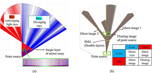
In this paper, we propose a novel aerial multi-view display that combines the point light source array configuration of the temporal multiplexing multi-view display with the real image forming optics of the aerial display. Figure depicts the proposed system. The proposed system consists of an array of LEDs, a digital micromirror device (DMD) panel, and a transmission type retroreflector plate. The LEDs are turned on sequentially to illuminate the DMD panel, which displays the perspective view images in synchronization. The light reflected from the DMD panel is collected by the transmission type retroreflector, generating the real images of the LEDs and the DMD panel on the user’s side at their mirror symmetric positions with respect to the plate.
Figure 1. Proposed system.
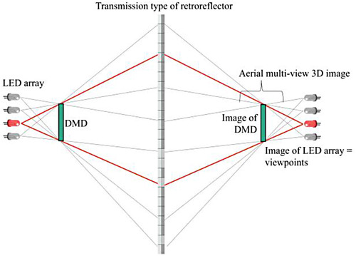
The real images of the LEDs serve as the viewpoints in the proposed system, such that the user in the viewpoint plane sees the aerial multi-view 3D images around the image plane of the DMD panel. The aerial nature of the image floating on the user’s side enhances depth perception and enables touch interaction without obstacles. Although there are previous studies on 3D aerial displays, they use spatial multiplexing based multi-view display technique [Citation38–40], which suffers from resolution loss. Our proposed system uses temporal multiplexing, displaying 3D aerial images with the full resolution of the DMD without any mechanical movement. In the following sections, we explain the principle, implementation, and experimental results of the proposed system in detail.
2. Principles of the proposed system
2.1. Transmission type retroreflector
A transmission type retroreflector is an optical plate that performs the retro-reflection only along the transverse axes of the plate. The light rays incident on the plate are reflected by the microstructure of the plate such that their transverse directional components are reverted while the longitudinal components are maintained without any change. A light beam diverging from an object point is converted into the converging beam by the transmission type retroreflector plate, forming the real image of the object at its mirror-symmetric position with respect to the plate. Therefore, the transmission type retroreflector can serve as an imaging device like usual lenses.
However, it possesses characteristics that differentiate it from conventional lenses, as illustrated in Figure . In the usual lens case, the magnification of the image is dependent on the object distance following the Gaussian lens law. In the transmission type retroreflector case, however, the image distance is the same as the object distance and thus the magnification of the image is always unity regardless of the object distance. Therefore, the transmission type retroreflector optically relays the objects at different distances to the other side of the plate, maintaining their size and distances. Another feature of the transmission type retroreflector is the depth order reversal. In the usual lens imaging, the real images of the objects at different depths are formed, maintaining their order. The real image A′ of the object A left to the object B in Figure is formed by the lens at the left of the real image B′ in the image space. In the transmission type retro-reflector case, however, their order is reversed as shown in Figure due to the mirror-symmetric imaging property.
Figure 2. Comparison of image formation between the lens and transmission type retroreflector. (a) Image after the lens. (b) Image after the transmission type retroreflector.
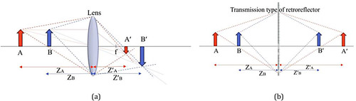
This unitary magnification and the depth order reversal property of the transmission type retroreflector plate are exploited in the proposed system to form the real image of the LED array in the viewpoint plane while forming the real image of the DMD panel in the space between the viewpoints and the plate.
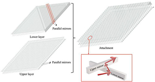
There are various device structures of the transmission type retroreflectors. In our study, a two-layer mirror array structure called the slit mirror array (SMA) is used. As depicted in Figure , each layer has numerous bi-reflecting mirror strips which are aligned in parallel to each other with hundreds of micrometer intervals. By stacking two mirror layers with orthogonal orientations, the SMA device effectively works as a corner reflector array, performing the transmission type retro-reflection.
Figure 3. SMA structure.
Unlike the ideal transmission type retroreflector, the SMA does not have 100% optical efficiency. Some of the light rays are not retro-reflected, forming the ghost images or DC light. In each layer, if the light ray encounters odd number of reflections between the neighboring mirror strips, its direction is reverted, while the original direction is maintained if it has even number of reflections.
Figure illustrates this point. Since two layers are stacked with orthogonal orientations, there are four combinations, i.e. even-even, even-odd, odd-even, and odd-odd types of reflection. Among them, only odd-odd reflections contribute to the desired floating image, while even-odd and odd-even reflections form the ghost images, respectively. The even-even part corresponds to the direct view of the object through the SMA. Figure shows the ray tracing simulation results obtained using MATLAB. In the simulation, every ray is represented by its position and direction which are subsequently updated through a series of reflections inside the SMA, resulting in the final trajectory shown in Figure . In the 2D simulation shown in Figure (a), the light rays diverging from a point source are incident on the single layer of the SMA. As shown in Figure (a), the rays that encounter odd number of reflections (red color) are retro-reflected in that axis, converging at the same transverse position as the point source on the opposite side of the plate. Meanwhile, the light rays that undergo the even number of reflections (blue color) proceed as the diverging light rays. In the 3D simulation with two layers shown in Figure (b), it is seen that the odd-even and even-odd number of reflections create two ghost images, and the even-even reflections serve as the direct view of the point source object through the plate. To separate these ghost images and direct view from the desired floating image, we tilt the SMA by 45° with respect to the optical axis of the incident light in our implementation, as proposed in previous studies [Citation41].
Figure 4. Different reflection types within two mirrors.
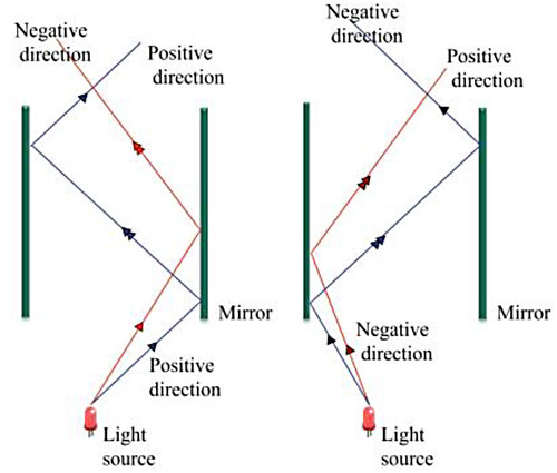
Figure 5. Ray tracing simulation of SMA. (a) 2D simulation of one mirror layer. (b) 3D simulation of both mirror layers.
2.2. The working principle of the proposed system
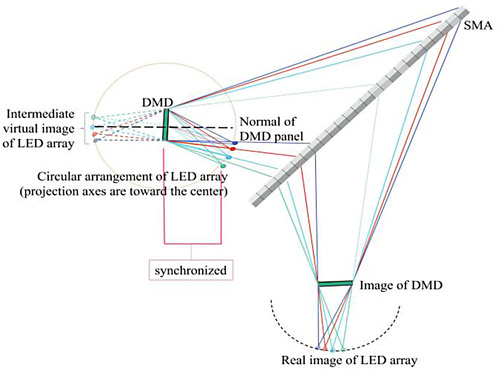
Figure shows the detailed configuration of our proposed aerial multi-view display. An LED array in a circular arrangement illuminates the DMD sequentially, and the DMD presents the corresponding perspective views of the desired 3D image in synchronization. The SMA tilted by 45° forms the real images of the DMD panel and the LED array on the user’s side, separating the ghost images and the direct view of the system from the desired images. The real image of each LED works as the viewpoint such that the eye located at the viewpoint sees the corresponding perspective view in the real image plane of the DMD. Due to the 1:1 magnification property of the SMA, the arrangement of the LED array and the DMD is maintained in the real image space after the SMA. The circular arrangement of the LED array guarantees that the light cone encompasses the DMD panel regardless of the number of LEDs, achieving uniform illumination on the DMD surface across the LEDs.
Figure 6. Detailed configuration of the proposed system.
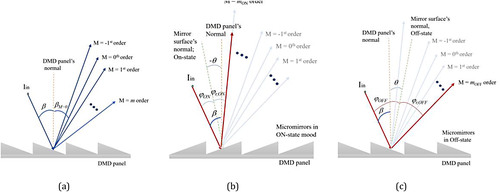
The light emanating from each LED is reflected by the DMD and then retro-reflected by the SMA to form the real image of the LED which works as the viewpoint. To determine the spatial position of the viewpoints, the position of the LED’s reflection by the DMD, i.e. the intermediate virtual image of the LED behind the DMD, needs to be obtained first. As depicted in Figure (a, b), DMD comprises binary pixel mirrors whose tilt angle is controlled to be either −θ ( = ON state) or +θ (=OFF state) with respect to the DMD surface normal. This configuration produces a blazed grating with a grating pitch of p. Note that due to its blazed grating structure, the light reflected from the DMD includes multiple diffractions around the strongest diffraction order, whose angle can be approximated to the reflection angle by the DMD pixel mirror. In this section, we limit our discussion to the reflection angle of the DMD pixel mirror. We will reserve a detailed exploration of the blazed structure and its impact on light diffraction for the discussion section.
Figure 7. Intermediate virtual image of an LED formed by a single pixel mirror of DMD. (a) ON state mirror. (b) OFF state mirror. (c) Angular difference between ON and OFF state pixel mirror images.
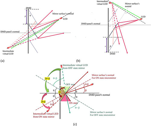
Figure (a, b) depicts the image formation of an LED via a single binary pixel mirror in its ON and OFF state, respectively. In each state, the pixel mirror forms the image of the LED at a symmetric position with respect to the mirror surface. When the LED is located at an angle β with respect to the DMD normal, the ON/OFF images of the LED are separated by (2θ + β) + (2θ − β) = 4θ angle, as illustrated in Figure (c).
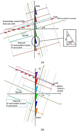
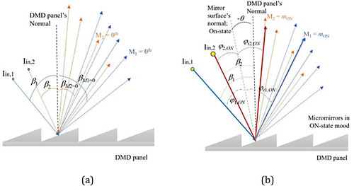
Figure (a, b) and Videos S1–S2 (online Supplemen-tal Material) depict the image formation by multiple pixel mirrors in ON or OFF state. In Figure (a, b), (x, z) and (x′, z′) are coordinate systems where z and z′ represent the DMD normal and pixel mirror normal, respectively. For an LED object at , each pixel mirror forms its image at the same transverse location at
, regardless of its position in the DMD plane. However, their longitudinal distances from the LED, i.e. z′ axis distances between the LED and the pixel mirrors are different, and each pixel mirror forms the LED images at different distances, i.e.
. Therefore, as shown in Figure (a, b), the LED images formed by multiple pixel mirrors lie in a common line
but are separated longitudinally. The longitudinal separation between the LED images formed by neighboring pixel mirrors is
, and the entire spread of the LED image in the longitudinal direction is given by
, where N is the number of pixel mirrors. Note that the existence of the longitudinal spread of the LED images is not ideal but its magnitude is small. In our implementation, the longitudinal spread is only about
which is negligible.
Figure 8. Calculation of the intermediate virtual LEDs’ position to determine the amount of blurriness. (a) ON state. (b) OFF state.
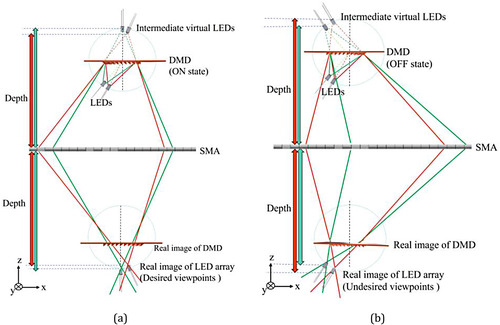
As illustrated in Figure (a, b), our proposed system is made up of the LED array in a circular arrangement in front of the DMD. Each LED illuminates the DMD surface in a time-sequential manner, and the DMD displays the binary bit-planes of the corresponding viewpoint image in synchronization. The ON and OFF state pixel mirrors of the DMD form the intermediate virtual LED images behind the DMD. The SMA creates the floating real image of the DMD and the LED array in a parity arrangement. As shown in Figure (a, b), the final LED array images corresponding to the ON and OFF state pixel mirrors are separated by 4θ, where the one formed by the ON state pixel mirrors is considered as the desired viewpoint array in the proposed method. When the eye is placed at each desired viewpoint, the corresponding image displayed by the DMD can be seen with the full resolution of the DMD.
Figure 9. LED array projecting on DMD in both states. (a) ON state. (b) OFF state.
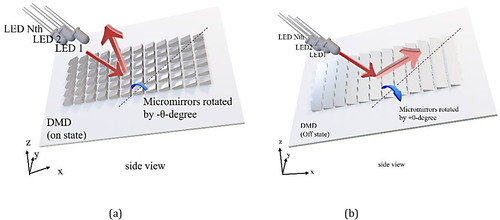
Figure 10. Viewpoints formation. (a) ON state. (b) OFF state.
3. Experimental result
Figure shows the experimental setup. We use 5 LEDs with a 4° separation in a circular arrangement with respect to the center of the DMD.
Figure 11. Experimental setup.
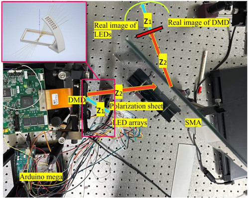
The distance between the LED and the DMD is 65 mm. Both the DMD and the LED array were mounted on a homemade 3D-printed zig shown in the inlet of Figure . The DMD used in our implementation is the Texas Instruments DLPLCR6500EVM model, which has 1920 × 1080 resolution and a 9523 Hz maximum refresh rate for the binary patterns. The binary tilt angle of the DMD pixel mirror is . A polarizing sheet was added right after the LED array to attenuate the luminance of the LED. For the SMA, a glass version of the ASKA3D plate [Citation42] is used. The SMA is located at 150 mm distance from the DMD with a
inclination. For the viewpoint image rendering, the V-Ray plugin for Autodesk 3ds Max is used. During the rendering, the V-Ray camera rotated around a 3D object and captured the viewpoint images with a 4° angular separation. The bit depth of the original rendered images was then adjusted to 4, using MATLAB, to represent 16 gray levels in each viewpoint image. The LED array and DMD were synchronized using an Arduino Mega 2560 board by sending the trigger signals to both devices. All results were captured using a Galaxy Ultra S21 camera.
Figure shows the synchronization scheme used in our implementation. At each frame (=viewpoint image), the Arduino board sends the trigger signal to turn on an LED and to display the corresponding viewpoint image. The LED is turned on for 1700 µsec, and the DMD displays 4 bit-planes of the viewpoint image during that time. The sub-frames’ time periods for the 4 bit-plane were 105, 210, 420, and 840 µsec, respectively, which adds up to 1575 µsec. In our implementation, the separation between the frame trigger was adjusted to 1700 µsec which is slightly larger than 1575 µsec to avoid any crosstalk caused by the signal and the device delays.
Figure 12. Time diagram for synchronization.

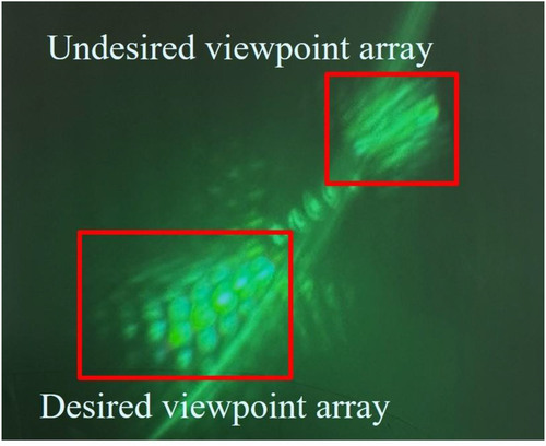
Figure shows the formation of the real image of the DMD panel and the viewpoints on the user’s side. In Figure (a), a diffuser is placed at the same distance as the DMD from the SMA. The clear rectangle shown in Figure (a) confirms the real image formation of the DMD panel in front of the SMA following the expectation. In Figure (b), a curved diffuser is placed in the LED image plane while the DMD displays only ON or OFF patterns. In the lower left part of Figure (b), 5 spots are visible which demonstrates the real image formation of the 5 LEDs in the user’s side.
Figure 13. Experimental results. (a) Image of the DMD panel. (b) Desired and undesired viewpoint array with a faint image of the LED array in between. (c) The angular separation of desired and undesired viewpoint from a single LED.
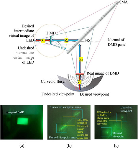
In Figure (b), another light is visible which corresponds to the undesired viewpoint array mentioned in the previous section. Note that faint points between the desired and undesired viewpoints are the LED images formed by the reflection at the planar frame around the active pixel matrix area of the DMD. The angular difference between the desired viewpoint and the undesired one is measured to be 48° as shown in Figure (c) where only a single LED is turned on, which agrees well with the expectation.
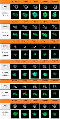
Figure and Videos S3–S8 (online Supplemental Material) show the displayed multi-view 3D images. In Figure , each picture was taken at the corresponding viewpoint. The image at each viewpoint represents the corresponding view of the 3D image without noticeable crosstalk. Note that the slight color variation across the viewpoints is observed in Figure . We believe that this variation came from the camera setting at the time of capturing and it is not visible in the video results shown in Videos S3–S8. These Videos were captured while moving the camera across the viewpoints. As seen in Videos S3–S8, the motion parallax of the 3D image is reproduced well, confirming the feasibility of the proposed system.
Figure 14. Experimental results.
4. Discussion
4.1. Image intensity variation across the viewpoints
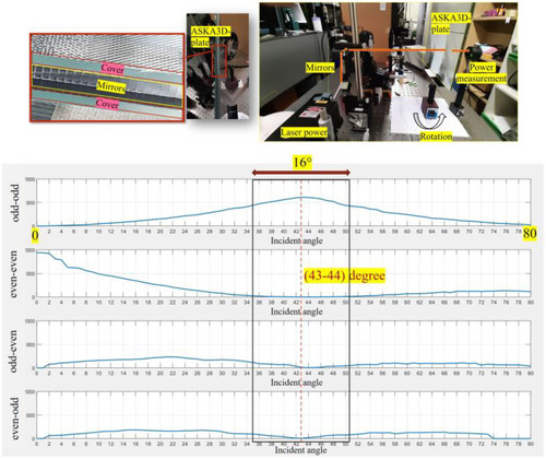
The experimental results of our implementation show a slight variation in image intensity across viewpoints. This variation comes from the angular dependence of the SMA optical efficiency. In the proposed system, the light from individual LEDs reaches the SMA at different incident angles, which leads to different image intensities for the viewpoints. Figure shows the MATLAB simulation results when parallel light rays are incident on the SMA with varying angles. In the simulation, the SMA is modeled as a stack of two orthogonal mirror strip array layers with the 0.5 mm separation and 1.4 mm height of the mirror strip. The incident light rays experience one of the four reflection types, i.e. odd (first layer)-odd (second layer), even-even, odd-even, and even-odd, when they pass through the two layers of the SMA. Refer to Appendix A for the reflection type identification for each light ray. Among the 4 reflection cases, only the odd-odd reflection gives the desired transverse retro-reflection, contributing to the 3D image formation of the proposed method. As shown in Figure , the 27° incident angle gives the highest odd-odd efficiency while keeping the other reflections at a minimum. In the actual SMA plate used in our experiment, i.e. the ASKA3D plate, there are cover layers made up of borosilicate glass with a refractive index of 1.5168. Therefore, the 27° incident angle inside the plate is equivalent to 43° in the air. We performed an experiment to verify this simulation result. In the experiment, the light power of 4 different reflection types was measured at varying rotation angles of the SMA plate. The experimental result in Figure shows the maximum odd-odd reflection at around 43° angle, confirming the accuracy of the simulation. In our experimental implementation, five LEDs produce an angle of 16°, which is equal to the 10.47° in the mirror layers. As a result, the image’s intensity seen from different perspectives changes within the range from 65% to 98% in the mirrored layers, as indicated within the black enclosure in Figures and . For uniform intensity across viewpoints, the current implementation can be improved by adjusting the intensity of the individual LED using pulse width modulation (PWM).
Figure 15. Simulation result: ratio of different reflection types.
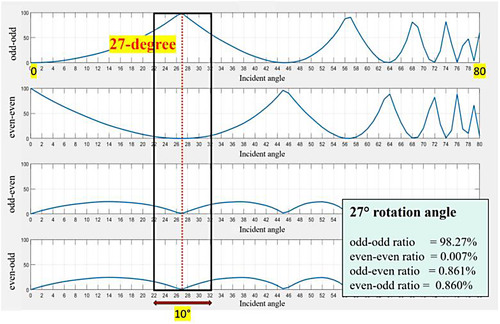
Figure 16. Experimental verification: ratio of different reflection types.
4.2. Image blur
Despite the favorable features of the SMA, it causes a slight blur in the images. Figure is a comparison between the image formed by a lens and the SMA, which indicates that the image formed by the SMA is blurry. Figure illustrates the path of light rays within the mirror space of the SMA. In the ideal case shown in Figure (a), the light rays enter and exit from the SMA at the same transverse, i.e. x position, making a sharp image in the mirror-symmetric position of the original point source. In the actual SMA, however, there is a small shift between the incident and exiting transverse positions, as shown in Figure (b), which leads to an out-of-focus image in the image plane. This maximum shift in the transverse position is given by the separation between the mirror strips. Given that light rays diverge in both positive and negative directions, the image of a single point source can be blurred up to twice the mirror separation, explaining the blurriness of the 3D images observed in our experimental implementation. We believe that this blur could be reduced by decreasing the SMA’s mirror separation from current 0.5 mm to a smaller value.
Figure 17. Image quality comparison between a lens and SMA.
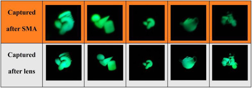
Figure 18. Comparison of the focused and blurry images. (a) Focused image. (b) Blurred image.

4.3. Effect of the diffraction by the DMD
In Figure , we show the results of the same experiment as in Figure , but without the polarization filter situated in front of the LED array. The absence of this filter causes replicated viewpoints to be visible. These replicated viewpoints, visible with reduced intensity, negatively affect the proposed system’s performance by causing crosstalk between the perspective images.
Figure 19. Non-desired diffraction orders are observed when the polarization sheet is not used.
These additional viewpoints are created by the diffracted light from the DMD. The DMD consists of the micro mirror pixels slanted by either +θ (OFF) or −θ (ON) angles. The slanted pixel mirror array structure of the DMD makes it work as a blazed grating, causing the diffraction [Citation43]. Figure shows the blazed grating diffraction of the DMD. When the light is incident on the grating with an angle β with respect to the DMD normal as shown in Figure (a), the diffraction orders are formed at
(1)
(1) where
is the diffraction angle of the M-th order with respect to the DMD normal. As the micro pixel mirror is slanted by +θ (OFF) or −θ (ON) angles, the maximum intensity is found at the diffraction order closest to the mirror reflection angle of the individual micro pixel mirror [Citation43], i.e.
in Figure (b) and (c). Note that the incident angles β and φ are measured to be positive toward left from the referenced axes and the reflected or diffracted angles
and
are positive toward the right in Figure . Approximating that
and
, which is true as the angular difference between the diffraction orders is small due to the relatively large pixel pitch
in our implementation, the strongest diffraction order of the DMD can be simply thought as the mirror reflection of the micro pixel mirror.
Figure 20. (a) Diffraction orders of the DMD. The strongest diffraction order in (b) ON state and (c) OFF state.
When multiple light beams are incident on the DMD as shown in Figure , their diffractions are distributed with their respective orders. Again, the maximum diffractions are found at the orders that coincide with the reflection angles of the micro pixel mirror. Therefore, the system design and analysis in Section 2.2 that consider only the mirror reflection can be justified. Although they have smaller intensity, there exist other diffraction orders as well. These other diffraction orders are converged by the transmission-type retroreflector on to the image of the DMD and then diverge to form the additional viewpoints shown in Figure . In our implementation, we found that by attenuating the LED light using a polarizer, these additional viewpoints are sufficiently suppressed without causing noticeable crosstalk.
Figure 21. (a) Diffraction order distribution for two incident beams, (b) strongest diffraction orders for two beams in the ON-state mode.
4.4. Longitudinal spread of viewpoints
As stated in Section 2.2, the intermediate virtual image of the LED placed behind the DMD has a longitudinal spread of 4.89 mm along the normal pixel mirror. Considering the pixel mirror angle, i.e. , the lateral spread of the LED image on the user’s side is estimated to be
mm and
mm, respectively. In our experimental implementation, the LEDs are placed with sufficient separation so that the longitudinal spread of the intermediate virtual image of the LED does not cause overlapping of the final viewpoints.
4.5. Comparison with other multi-view displays
The proposed system presents aerial 3D images floating on the user side of the device. Unlike most of the conventional aerial displays using reflection-type or transmission type retroreflectors [Citation22–35] that only float the 2D images, the proposed system presents multi-view 3D images, giving more natural imagery to the users. When compared with conventional 3D aerial displays that combine the spatial-multiplexing multi-view technique and the retroreflector [Citation38–40], the proposed method has an advantage in resolution as it uses time-multiplexing without sacrificing the native resolution of the display panel. While the multi-view displays without the retroreflectors present 3D images only around the display panel, the proposed system forms the floating 3D images well apart from the physical display panel, giving a higher visual effect to the user.
However, the current implementation of the proposed system still has many challenges to overcome when compared with other recent multi-view displays. The first is the image size. Large image sizes are important for providing an immersive 3D experience. Recent multi-view displays based on the LCD panel and the pixel-wise grating [Citation44–49] or lenticular lens easily achieve the large image size over 65 in. [Citation50]. To the contrary, the image size of the proposed system is limited by the highspeed DMD panel, which is only 0.65 in. in our current implementation. We believe that the image size can be increased by either adopting magnifying optics before the transmission-type retroreflector or replacing the DMD with a large, high-refresh-rate LCD panel without its backlight unit in the proposed system.
The second limitation is the system form factor. Unlike the conventional multi-view displays, which maintain a flat and thin form factor [Citation44–50], the proposed system requires a volumetric form factor due to the use of a transmission-type retroreflector slanted at 45°. However, this relatively large form factor is common for all aerial displays. We believe that the proposed system can be adopted in many applications where the aerial nature of the presented images is important, like in other conventional aerial displays [Citation22–35]. Moreover, the recently developed on-axis transmission-type retroreflector technique [Citation51] can be applied to the proposed system, removing the requirement of the 45° tilt and reducing the overall form factor.
Lastly, the resolution of our current implementation is degraded by the transmission-type retroreflector and the DMD diffractions. We think that the use of the large-screen fast LCD panel and the imaging quality enhancement of the retroreflector would help the resolution enhancement, making the best use of the inherent advantage of the proposed time-multiplexing scheme, i.e. the resolution preservation regardless of the number of views.
5. Conclusion
In this paper, we propose a novel aerial multi-view display using an SMA and LED array. The LED array illuminates the DMD in a time-multiplexing manner, and the SMA forms the aerial 3D image and the viewpoint on the user side. In our experimental implementation, the aerial 3D images with five different perspectives were displayed successfully with the full resolution of the DMD. The proposed method has the potential to provide more full-resolution perspectives with both horizontal and vertical parallax if a faster DMD is utilized.
Supplemental Material
Download MP4 Video (186 KB)Supplemental Material
Download MP4 Video (134.1 KB)Supplemental Material
Download MP4 Video (136.8 KB)Supplemental Material
Download MP4 Video (85.4 KB)Supplemental Material
Download MP4 Video (211.3 KB)Supplemental Material
Download MP4 Video (109.1 KB)Supplemental Material
Download MP4 Video (1.3 MB)Supplemental Material
Download MP4 Video (1.4 MB)Disclosure statement
No potential conflict of interest was reported by the author(s).
Additional information
Funding
Notes on contributors

Sahar Kheibarihafshejani
Sahar Kheibarihafshejani earned her Bachelor of Engineering in Electronic and Communication Engineering from Bu-Ali Sina University, Iran, in 2017. She continued her academic journey by completing her Master's degree in Information and Communication Engineering at Inha University, South Korea, in 2021. Currently, she is pursuing her Ph.D. in the same field at Inha University, with research interests focusing on autostereoscopic 3D display systems using holography and light field technology.

Jae-Hyeung Park
Jae-Hyeung Park received his Bachelor of Science, Masters in Science and Ph.D from Seoul National University in 2000, 2002, and 2005, respectively. He joined Samsung Electronics in 2005 and worked on the development of motion-blur reduction techniques for liquid crystal displays. From 2007 to 2012, he was a faculty member of Chungbuk National University, and from 2013 to 2023, he was with Inha University. In 2024, he joined the faculty of Seoul National University as an associate professor. He has been working on the acquisition, processing, and display of three-dimensional information using holography and light field techniques, and his more recent research focuses on AR and VR near-eye-displays.
References
- L. Lipton, Foundations of the Stereoscopic Cinema (Van Nostrand Reinhold, 1982). <http://www.stereoscopic.org>.
- D.F. McAllister (Ed.), Stereo Computer Graphics and Other True 3D Technologies, ISBN 0-691-08741-5 (Princeton University Press, Princeton, 1993).
- A. Schwerdtner and H. Heidrich, Dresden 3D Display (D4D), in Proceedings of SPIE 3295, Stereoscopic Displays and Virtual Reality Systems V (30 April 1998). doi:10.1117/12.307165.
- D. Fattal, Z. Peng, T. Tran, S. Vo, M. Fiorentino, J. Brug, and R.G. Beausoleil, A multi-directional backlight for a wide-angle, glasses-Free three-dimensional display, Nature 495 (7441), 348–351 (2013). doi:10.1038/nature11972.
- Holografika. <www.holografika.com>.
- T. Balogh and P. T. Kov´acs, Real-time 3D light field transmission, in Proceedings of SPIE 7724, Real-Time Image and Video Processing 2010, 772406 (4 May 2010). doi:10.1117/12.854571.
- S. Yoshida, fVisiOn: 360-degree viewable glasses-free tabletop 3D display composed of conical screen and modular projector arrays, Opt. Express 24, 13194–13203 (2016).
- W. Matusik, and H. Pfister, 3D TV: a scalable system for real-time acquisition, transmission, and autostereoscopic display of dynamic scenes, ACM Trans. Graph 23 (3), 814–824 (August 2004). ISSN 0730-0301. doi:10.1145/1015706.1015805.
- E. Goulanian and A. F. Zerrouk, U.S. Patent NO.7,944,465 (May 17, 2011).
- L. Bogaert, Y. Meuret, S. Roelandt, A. Avci, H.D. Smet, and H. Thienpont, Demonstration of a multiview projection display using decentered microlens arrays, Opt. Express 18, 26092–26106 (2010).
- O.S. Cossairt, J. Napoli, S.L. Hill, R.K. Dorval, and G.E. Favalora, Occlusion-capable multiview volumetric three-dimensional display, Appl. Opt. 46, 1244–1250 (2007). doi:10.1364/AO.46.001244.
- J. Geng, A volumetric 3D display based on a DLP projection engine, Displays 34 (1), 39–48 (2013). ISSN 0141-9382. doi:10.1016/j.displa.2012.11.001.
- J. Kim, Y. Lim, K. Hong, H. Kim, H.-E. Kim, J. Nam, J. Park, J. Hahn, and Y.-J. Kim, Electronic tabletop holographic display: design, implementation, and evaluation, Appl. Sci. 9 (4), 705 (2019). doi:10.3390/app9040705.
- W.-X. Zhao, H.-L. Zhang, Q.-L. Ji, H. Deng, and D.-H. Li, Aerial projection 3D display based on integral imaging, Photonics 8 (9), 381 (2021). doi:10.3390/photonics8090381.
- D. Lanman, M. Hirsch, Y. Kim, and R. Raskar, Content-adaptive parallax barriers: optimizing dual-layer 3D displays using low-rank light field factorization, ACM Trans. Graph 29, 163 (2010).
- G. Wetzstein, D. Lanman, M. Hirsch, and R. Raskar, Tensor displays: compressive light field synthesis using multilayer displays with directional backlighting, ACM Trans. Graph 31, 80 (2012).
- W. Han, J. Han, Y.-G. Ju, J. Jang, and J.-H. Park, Super multi-view near-eye display with a lightguide combiner, Opt. Express 30, 46383–46403 (2022).
- T. Ueno, and Y. Takaki, Super multi-view near-eye display to solve vergence–accommodation conflict, Opt. Express 26, 30703–30715 (2018).
- S. Lim, H. Jeon, M. Jung, C. Lee, W. Moon, K. Kim, H. Kim, and J. Hahn, Fatigue-free visual perception of high-density super-multiview augmented reality images, Sci. Rep. 12 (1), 2959 (2022). doi:10.1038/s41598-022-06778-4.
- H. Kakeya, A full-HD super-multiview display with time-division multiplexing parallax barrier, Dig. Tech. Pap. Soc. Inf. Disp. Int. Symp 49 (1), 259–262 (2018).
- Y. Watanabe, and H. Kakeya, A super-multiview display with horizontal and vertical parallax by time division and color multiplexing, SID Symp. Digest Tech. Pap. 51, 1017–1020 (2020).
- H. Yamamoto, Y. Tomiyama, and S. Suyama, Floating aerial LED signage based on aerial imaging by retro-reflection (AIRR), Opt. Express 22, 26919–26924 (2014).
- H. Kikuta, M. Yasugi, and H. Yamamoto, Consideration of image processing system for high visibility of display using aerial imaging optics, Opt. Rev. 31, 144–155 (2024).
- S. Sakane, D. Kudo, N. Mukojima, M. Yasugi, S. Suyama, and H. Yamamoto, Formation of multiple aerial LED signs in multiple lanes formed with AIRR by use of two beam splitters, Opt. Rev. 30, 84–92 (2023).
- S. Sakane, S. Suyama, and H. Yamamoto, Reducing thickness of long-distance aerial display system in AIRR using Fresnel lens, Opt. Rev. 30, 657–663 (2023).
- I. Nakao, T. Sakamoto, and M. Yamaguchi, See-through aerial display using a dihedral corner reflector array and hologram mirrors, Appl. Opt. 60, 9896–9905 (2021).
- N. Koizumi, and A. Sano, Optical system to display mid-air images on a glossy plane and remove ground images, Opt. Express 28, 26750–26763 (2020).
- H. Yamamoto, H. Kajita, N. Koizumi, and T. Naemura, EnchanTable: displaying a vertically standing mid-air image on a table Surface using reflection, in Proceedings of the 2015 International Conference on Interactive Tabletops & Surfaces (ITS ‘15), Madeira, Portugal, pp. 397–400 (2015). doi:10.1145/2817721.2823476.
- Y. Matsuura and N. Koizumi, Scoopirit: a method of scooping mid-air images on water surface, in Proceedings of the 2018 ACM International Conference on Interactive Surfaces and Spaces (ISS ‘18), Tokyo, Japan, pp. 227–235 (2018). doi:10.1145/3279778.3279796.
- Y. Osato, and N. Koizumi, Compact optical system displaying mid-air images movable in depth by rotating light source and mirror, Computers & Graphics 91, 290–300 (2020). ISSN 0097-8493. doi:10.1016/j.cag.2020.08.006.
- H. Kajita, N. Koizumi, and T. Naemura, SkyAnchor: optical design for anchoring mid-air images onto physical objects, in Proceedings of the 29th Annual Symposium on User Interface Software and Technology (UIST ‘16), Tokyo, Japan, pp. 415–423 (2016). doi:10.1145/2984511.2984589.
- H. Kim, I. Takahashi, H. Yamamoto, S. Maekawa, and T. Naemura, MARIO: mid-air augmented reality interaction with objects, Entertainment Comput. 5 (4), 233241 (2014). ISSN 1875-9521. doi:10.1016/j.entcom.2014.10.008.
- N. Hashimoto and K. Murofushi, Wide viewing angle 3D aerial display using micro-mirror array plates and aerially-coupled 3D light sources, in ACM SIGGRAPH 2020 Posters (SIGGRAPH ‘20), New York, NY, USA, Article 37, pp. 1–2 (2020). doi:10.1145/3388770.3407396.
- N. Hashimoto and K. Hamamoto, Aerial 3D display using a symmetrical mirror structure, in ACM SIGGRAPH 2018 Posters (SIGGRAPH ‘18), New York, NY, USA, Article 31, pp. 1–2 (2018). doi:10.1145/3230744.3230746.
- M. Takenawa, T. Kikuchi, Y. Yahagi, S. Fukushima, and T. Naemura, ReQTable: square tabletop display that provides dual-sided mid-air images to each of four users, in ACM SIGGRAPH 2022 Emerging Technologies (SIGGRAPH ‘22), Article 8, pp. 1–2 (2022). doi:10.1145/3532721.3535563.
- M. Park, H. Jeon, D. Heo, S. Lim, and J. Hahn, 360-degree mixed reality volumetric display using an asymmetric diffusive holographic optical element, Opt. Express 30, 47375–47387 (2022). doi:10.1364/OE.476965
- T. Nakamura, T. Yano, K. Watanabe, Y. Ishii, H. Ono, I. Tambata, N. Furue, and Y. Nakahata, 360-degree transparent holographic screen display, in ACM SIGGRAPH 2019 Emerging Technologies (SIGGRAPH ‘19), Article 1, pp. 1–2 (2019).
- N. Zhang, T. Huang, X. Zhang, C. Hu, and H. Liao, Omnidirectional 3D autostereoscopic aerial display with continuous parallax, J. Opt. Soc. Am. A 39, 782–792 (2022).
- H.-L. Zhang, H. Deng, H. Ren, X. Yang, Y. Xing, D.-H. Li, and Q.-H. Wang, Method to eliminate pseudoscopic issue in an integral imaging 3D display by using a transmissive mirror device and light filter, Opt. Lett. 45, 351–354 (2020).
- S. Kheibarihafshejani and J. Park, Superimposition of two integral imaging systems for depth enhancement by using polarization grating and dihedral corner reflector, in Frontiers in Optics + Laser Science 2022 (FIO, LS), Technical Digest Series (Optica Publishing Group, 2022), paper JTu4A.74.
- S.P. Hines. US Patent No. 6,817,716 B1 (16 November 2004).
- Asukanet Co., Ltd. <https://aska3d.com/en/index.html>.
- B. Smith, B. Hellman, A. Gin, A. Espinoza, and Y. Takashima, Single chip lidar with discrete beam steering by digital micromirror device, Opt. Express 25, 14732–14745 (2017).
- J. Shi, W. Qiao, J. Hua, R. Li, and L. Chen, Spatial multiplexing holographic combiner for glasses-free augmented reality, Nanophotonics 9, 243 (2020).
- W. Wan, W. Qiao, D. Pu, R. Li, C. Wang, Y. Hu, H. Duan, L.J. Guo, and L. Chen, Holographic sampling display based on metagratings, iScience 23, 100773 (2020).
- J. Hua, E. Hua, F. Zhou, J. Shi, C. Wang, H. Duan, Y. Hu, W. Qiao, and L. Chen, Foveated glasses-free 3D display with ultrawide field of view via a large-scale 2D-metagrating complex, Light Sci. Appl. 10, 213 (2021).
- J. Shi, W. Qiao, J. Hua, R. Li, and L. Chen, Spatial multiplexing holographic combiner for glasses-free augmented reality, Nanophotonics 9, 3003–3010 (2020).
- <https://www.continental.com/en-us/press/press-releases/continental-leia-3d-lightfielddisplay/>.
- <https://www.leiainc.com>.
- <https://lookingglassfactory.com/portrait>.
- D. Min, M.-H. Choi, and J.-H. Park, Compact in-line floating display system using dihedral corner reflector array, Opt. Express 29 (2), 1188–1209 (2021).
Appendix A:
Reflection type identification
Figure A1. Positive direction, an odd number of reflections.
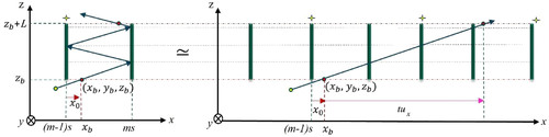
The SMA is made of parallel mirrors in each layer. A light ray that is incident on the bottom surface of the SMA experiences multiple reflections between two neighboring mirrors before exiting the SMA from its top surface. The number of the reflections can be calculated from the position and direction of the incident ray.
Suppose that the SMA layer is made of parallel mirrors with a separation of s and the height L. All mirrors are oriented along the y axis as shown in Figure so that the x-axis position of the m-th mirror is given ms. Consider a light ray that enters the bottom surface of the SMA layer at the position (xb, yb, zb) with an unit direction vector (ux, uy, uz) where xb is between (m − 1)s and ms and uz > 0. The multiple reflections between (m − 1)-th and m-th mirrors shown in the left part of Figure A.1 can be unfolded as shown in the right part of Figure A1. Note that we explain the only one case where xb > 0 and ux > 0 for simplicity, other cases can also be analyzed in the same way. Denoting the local x position of the incident light ray from the (m − 1)-th mirror as , the number of reflections Nr that the ray experiences before exiting the top surface of the SMA layer is given by
(A1)
(A1) where t is given by
. This process is repeated for two layers of the SMA, enabling the reflection type identification among odd-odd, odd-even, even-odd, and even-even cases.