
Abstract
We developed a high-performance CdSe/ZnS quantum-dot light-emitting diode (QLED) incorporating a hole injection layer (HIL) composed of a solution-processed vanadium oxide (VO) and molybdenum oxide (MoO) mixture. The QLED with a VO:MoO ratio of 1:1 in the HIL demonstrated a current efficiency of 62.0 cd/A, representing a 60% improvement over the QLED utilizing poly(3,4-ethylenedioxythiophene) polystyrene sulfonate (PEDOT:PSS) as the HIL. Besides improved performance, the substitution of the highly reactive PEDOT: PSS with chemically stable metal oxides in HIL fabrication is anticipated to enhance device reliability. The highest occupied molecular orbital level of the VO:MoO ratio of 1:1 HIL was higher than that of HILs with other mixing ratios. Additionally, the VO:MoO ratio of 1:1 HIL exhibited higher oxidation number states compared to HILs with other mixing ratios. These characteristics contributed to the superior performance of the QLED with the VO:MoO ratio of 1:1 HIL. Our approach, which employs chemically stable metal oxides as HIL materials for high-performance QLEDs, can advance future QLED technology.
1. Introduction
As electronic information becomes more integrated into daily life, the interface between humans and electronic systems grows increasingly important. A critical component of this interface is the electronic display, facilitating visual interaction with digital content. Organic light-emitting diodes (OLEDs) dominate this technology, offering impressive performance and widespread adoption in electronic devices [Citation1,Citation2]. However, the demand for advancements beyond OLEDs remains. Quantum-dot light-emitting diodes (QLEDs) emerge as the frontrunner among next-generation display technologies [Citation3–5]. The emission spectra of QLEDs are shaped by the quantum confinement effect, resulting in sharper emission spectra and a larger color gamut compared to OLEDs [Citation6,Citation7]. Additionally, the controllability of QLED colors through quantum dot (QD) size adjustment simplifies fabrication when contrasted with OLEDs, requiring changes in emission materials to achieve different colors.
Research on QLEDs is still in its nascent stages compared to that of OLEDs. Consequently, significant issues must be addressed for QLEDs to surpass OLEDs and become the dominant display technology. One crucial challenge is enhancing device efficiency. Numerous studies have aimed to improve the efficiency of QLEDs in terms of electron and hole charge balance within QD emission layers (EMLs) [Citation8–12]. Typically, electron injection into QLEDs is easier than hole injection, leading to a potential charge imbalance that can degrade QLED performance. As a result, achieving charge balance has been a pivotal research focus. Poly(3,4-ethylenedioxythiophene) polystyrene sulfonate (PEDOT:PSS), widely used as a hole injection layer (HIL) material in high-performance QLEDs, exhibits favorable hole injection properties [Citation13–15]. However, it also possesses some drawbacks, such as damaging underlying anode materials due to its high chemical reactivity.
Efforts to fabricate high-performance QLEDs by adopting metal oxide HILs have been ongoing, aiming to replace PEDOT:PSS HILs. For instance, metal oxide HILs have been explored due to their lack of damaging effects on underlying layers and increased resistance to environmental damage compared to PEDOT:PSS HILs, making them promising candidates for high-performance HIL materials [Citation16–18]. Reports on QLEDs with solution-processed vanadium oxide (VO) HILs [Citation19–26] and molybdenum oxide (MoO) HILs [Citation27–33] have also emerged. Among these, QLEDs with VO HILs demonstrated fairly good performance. However, the performance of QLEDs with metal oxide HILs still falls short of surpassing QLEDs with PEDOT: PSS HILs. Hence, to address the performance challenges associated with QLEDs utilizing metal oxide HILs, we propose adopting HILs composed of mixed metal oxide materials. This study investigated mixed metal oxide HILs comprising VO and MoO. Specifically, we analyzed their properties and assessed device performance based on varying mixing ratios. Through this investigation, we aim to manipulate the HIL properties and determine the optimal conditions for achieving high-performance QLEDs.
2. Experiments
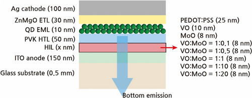
Bottom-emission QLEDs were fabricated on glass substrates employing a stack structure featuring a bottom anode and a top cathode. The device layers comprised a glass substrate, an indium tin oxide (ITO) anode, an HIL, a poly(9-vinylcarbazole) (PVK) hole transporting layer (HTL), a CdSe/ZnS QD EML, a ZnMgO electron transporting layer (ETL), and an Ag cathode (refer to Figure ). On the 0.5-mm-thick glass substrate, a 150-nm-thick ITO anode was deposited via reactive sputtering and patterned using photolithography. Various materials were spin-coated onto the anode to serve as the HIL, including 25-nm-thick PEDOT:PSS, 10-nm-thick VO, 8-nm-thick MoO, and 8-nm-thick mixed metal oxide layers. The atomic mixing ratio of the mixed metal oxide layers ranged from 1:0.1 to 20 of VO:MoO. Then, a 50-nm-thick PVK HTL was spin-coated onto the HIL, followed by the spin-coating of a 10-nm-thick CdSe/ZnS QD EML onto the HTL. A 30-nm-thick ZnMgO ETL was then spin-coated onto the EML. Finally, a 100-nm-thick Ag cathode was deposited onto the ETL via vacuum thermal evaporation and patterned using a metal shadow mask. The thickness values of PVK HTL, QD EML, ZnMgO ETL, and PEDOT:PSS HIL were measured using an ET-200 surface profiler (Kosaka Laboratory, Japan). The thickness values of metal oxide HIL were extracted from the X-ray photoelectron spectroscopy (XPS) depth profile data.
Figure 1. The schematic of the structure of TQLEDs.
MoO, VO, and ZnMgO were synthesized in-house. To synthesize MoO, the bis(acetylacetonato) dioxomolybdenum(VI) precursor was dissolved in anhydrous 2-methoxyethanol to form a precursor 0.01 mol solution. This solution was then subjected to microwave irradiation at 2.54 GHz for 60 s. Subsequently, the treated solution was cooled to room temperature and filtered through a polyvinylidene fluoride membrane filter with 0.45-μm pores [Citation34]. To synthesize VO, the vanadium(V) triisopropoxide oxide precursor was dissolved in isopropyl alcohol to create a precursor solution with 0.01 mol concentration. This solution was stirred for 10 min at 600 rpm using an agitator. Subsequently, hydrolysis was conducted by adding pure water, followed by an additional stirring for 20 min at 600 rpm [Citation35]. ZnMgO with a magnesium content of 10-wt% was synthesized via the sol–gel method using zinc acetate dihydrate and magnesium acetate tetrahydrate as precursors, with dimethyl sulfoxide serving as the solvent [Citation36]. Tetramethylammonium hydroxide pentahydrate (TMAH) served as the oxidizing agent and was dissolved in anhydrous ethyl alcohol. The TMAH solution was then added to the zinc and magnesium precursor solution and stirred. Afterward, ethyl acetate was mixed with the stirred solution, resulting in the precipitation of ZnMgO. The ZnMgO precipitate was separated through centrifugation at 12,000 rpm for 3 min. The precipitated ZnMgO was then dispersed in ethyl alcohol and used for the ETL coating process.
The characteristics of the fabricated QLEDs were analyzed using a current density – voltage – luminescence (J – V – L) measuring system consisting of a computer-controlled source meter (Keithley 2450, Tektronix, USA) and a spectrophotometer (PR 650, JADAK, USA). The bonding states of HIL materials were examined through XPS analysis, and their energy band properties were evaluated through ultraviolet photoelectron spectroscopy (UPS) and ultraviolet–visible (UV-Vis) transmittance spectroscopy measurements.
3. Results and discussion
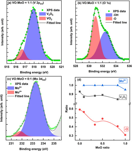
The XPS analysis was conducted on the metal oxide HIL materials to determine their bonding states. Figure synthesizes the XPS results. Particularly, Figure (a) demonstrates that the VOs within the VO:MoO HILs comprised V2O5 and VO2 states. Deconvolution of the V 2p3/2 peak revealed distinct peaks at 517.93 and 516.66 eV corresponding to V2O5 and VO2, confirming the presence of VO with varying oxidation states [Citation37,Citation38]. Additionally, Figure (b) confirms the O 1s peak, which could be deconvoluted into peaks at 530.97 and 532.41 eV attributed to oxygen from – O and – OH bonds, indicating the presence of a significant amount of – OH bonds in the VO:MoO HILs [Citation39]. Figure (c) displays the Mo 3d5/2 peak from the MoO HILs deconvoluted into peaks at 231.83 and 233.29 eV corresponding to Mo4+ and Mo6+, verifying the existence of MoO with varying oxidation states [Citation38,Citation40]. The majority of Mo exhibited Mo6+ states, implying that MoO primarily comprised the MoO3 state, albeit with a minor portion of the MoO2 state. Figure (d) depicts the bonding state ratios according to the MoO mixing ratio in the VO:MoO HILs. The bonding state ratios were calculated from the XPS peak areas, where the Mo6+ ratio was determined as the Mo6+ peak area divided by the sum of the Mo6+ peak area and the Mo4+ peak area. Similarly, the V2O5 ratio was calculated as the V2O5 peak area divided by the sum of the V2O5 peak area and the VO2 peak area, while the – O ratio was determined as the – O peak area divided by the sum of the – O peak area and the – OH peak area. The V2O5 ratio was the highest for the 0.5 MoO ratio, corresponding to the VO:MoO = 1:1 case, among the VO:MoO mixture HILs. In these mixtures, Mo bonding exclusively occurred in the Mo6+ states. Interestingly, only pure MoO HILs exhibited Mo4+ states and Mo6+ ratios less than 1.0. Overall, the quantity of – O states decreased as the MoO mixing ratio increased. Specifically, for the VO:MoO = 1:1 HIL, the – O state ratio was approximately 0.5. The HIL of VO:MoO = 1:1 demonstrated overall favorable bond states; the Mo was entirely in the MoO3 state, the V2O5 ratio was highest among the other VO:MoO mixtures, and the – O ratio was higher than others, except for extremely low MoO mixing ratio cases.
Figure 2. XPS peak analysis of (a) V 2p5/2 peak and (b) O 1s peak of VO:MoO = 1:1 film, (c) Mo 3d5/2 peak of MoO film, and (d) peak ratio variations according to MoO mixing ratio. Peaks in Figure (a–c) were deconvoluted using Gaussian functions.
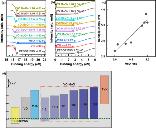
The energy bands were analyzed using UPS and UV-Vis transmittance spectroscopy [Citation12]. UPS results from the secondary electron cutoff region and the highest occupied molecular orbital (HOMO) region are depicted in Figure (a,b), respectively. Optical bandgap energies were extracted from Tauc plots obtained via UV-Vis transmittance spectroscopy, and their values according to the MoO mixing ratio are detailed in Figure (c). As illustrated in the figure, the bandgap energy increases as the MoO ratio increases. Figure (d) graphs the bandgap energies, utilizing a fixed vacuum level for all layers. The green dotted line in the diagram represents the HOMO level of the VO:MoO = 1:1 HIL. Notably, the HOMO of the VO:MoO = 1:1 HIL is the highest among all the HILs measured, underscoring the suitability of VO:MoO = 1:1 metal oxide as a HIL material, owing to the low hole injection barrier from the anode into the HIL. This low injection barrier is advantageous for achieving electron–hole balance in QLEDs. The values in Figure (a) signify the work function values of each layer. In Figure (b), the values denote the HOMO level positions relative to the Fermi level of each layer. The HOMO level position relative to the vacuum level was estimated by adding the work function obtained from Figure (a) to the HOMO level position obtained from Figure (b). The lowest unoccupied molecular orbital (LUMO) level was estimated by adding the band gap energy obtained from Figure (c) to the HOMO level. Utilizing these HOMO and LUMO levels, the energy bands portrayed in Figure (d) are derived [Citation41].
Figure 3. (a) Secondary electron cutoff and (b) HOMO regions of the UPS spectra of HILs, (c) bandgap energy of VO:MoO HILs according to the MoO mixing ratio, and (d) energy bands of HILs and PVK HTL. A fixed vacuum level for all layers was used for this diagram. The green dotted line indicates the HOMO level of the VO:MoO = 1:1 HIL.
To evaluate hole injection capability, hole-dominant devices without ETLs were fabricated using an identical structure and fabrication as the QLEDs, except for the absence of ETLs. Figure (b) depicts the device structure. Eliminating the ETL reduces the electron injection from the cathode, thereby inducing hole dominance within the devices. This approach facilitated the evaluation of hole injection and transport performance through the current density curves of the hole-dominant devices. Figure (a) demonstrates the current density curves corresponding to the Mo mixing ratio. Remarkably, at the 0.5 MoO ratio, VO:MoO = 1:1, the current density was the highest, indicating superior hole injection and transport performance. This observation may be attributed to the elevated HOMO level of the VO:MoO = 1:1 HIL, as depicted in Figure (d).
Figure 4. (a) Current density – bias voltage curves of hole-dominant devices according to the MoO mixing ratio in VO:MoO HIL materials and (b) schematic illustrating the device structure of the hole-dominant devices.
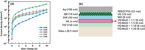
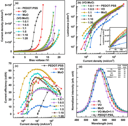
Figure illustrates the characteristics of the fabricated QLED. Figure (a) specifies the current density curves as a function of bias voltage according to the HIL materials. The current-on voltages of QLEDs with metal oxide HILs were higher than those of QLEDs with PEDOT:PSS HIL. This higher current-on voltage can be attributed to the insulating nature of metal oxide HIL materials. Figure (b,c) display the luminance curves and current efficiency curves as a function of current density, respectively. Notably, the QLED with the VO:MoO = 1:1 HIL exhibited the highest luminance and current efficiency, which can be attributed to the proper energy band positions of the VO:MoO = 1:1 HIL material. The maximum current efficiency of the QLED with the VO:MoO = 1:1 HIL reached 62.0 cd/A, marking a 60% improvement compared to the 38.8 cd/A current efficiency of the QLED with the PEDOT:PSS HIL. Figure (d) presents the EL spectra of the QLEDs according to the HIL materials, where the peak wavelengths of the QLEDs’ EL spectra red-shifted, and the FWHM values of the EL spectra increased compared to those of the PL spectrum. These red shifts and FWHM widening can be explained by the quantum-confined Stark effect [Citation6]. The discrepancy in HIL material properties can lead to differences in the EL peak wavelength based on the chosen HIL materials. Utilizing various HIL materials can alter the charge distribution within each layer, consequently affecting the electric field intensity across QDs. These variations in electric field intensity across QDs may lead to discrepancies in the EL peak wavelength, as reflected in Figure (d).
Figure 5. (a) Current density – bias voltage curves, (b) luminance – current density curves, and (c) current efficiency – current density curves of QLEDs according to the HIL materials. (d) PL and EL spectra of QLEDs. The HIL materials of the QLEDs are indicated in the figure legends. Luminance – current density curves in linear scale are shown as an inset in Figure (c), and the table showing peak wavelength and FWHM values is represented as an inset in Figure (d).
4. Conclusions
A comprehensive study of QLEDs with solution-processed metal oxide HILs was conducted to replace the conventional PEDOT: PSS HIL and enhance device performance. VO and MoO were chosen as the metal oxide materials based on their reported abilities as HIL materials in previous research. To improve the properties of metal oxide HILs and achieve QLEDs with significantly higher performance than those with PEDOT:PSS HILs, we proposed adopting a mixture of VO and MoO as the HIL material. The dependence of metal oxide properties on the mixing ratio of VO and MoO was meticulously examined. The bonding states of VO were confirmed to include V2O5 and VO2 states, while MoO was predominantly in the MoO3 state for all mixtures of VO and MoO, except for pure MoO, which exhibited a small portion of lower oxidation states in addition to the main MoO3 state. Furthermore, a considerable amount of – OH bonded states were found in all metal oxide HIL materials. The energy band levels of the metal oxide HIL materials varied according to the MoO mixing ratio, with the VO:MoO = 1:1 HIL material exhibiting the highest HOMO level and oxidation numbers higher than those of other VO:MoO HILs. The findings indicate that the VO:MoO = 1:1 HIL was instrumental in achieving high-performance QLEDs. This expectation was validated by fabricating QLEDs with different VO:MoO mixing ratios, with the QLED featuring the VO:MoO = 1:1 HIL, displaying a current efficiency of 62.0 cd/A, a remarkable 60% improvement compared to the current efficiency of the QLED with PEDOT:PSS HIL.
In summary, we proposed a method to develop high-performance HILs by adopting a mixture of solution-processed metal oxides as the HIL and demonstrated the validity of this approach by achieving a 60% improvement in efficiency with the VO:MoO = 1:1 HIL. This result represents a significant advancement in developing practical high-performance QLED technologies.
Disclosure statement
No potential conflict of interest was reported by the author(s).
Additional information
Funding
Notes on contributors

Suyoung Kim
Suyoung Kim received an M.Sc. from the Department of Electronic Materials, Devices, and Equipment Engineering at Soonchunhyang University, Asan, South Korea, in 2024. He has been researching quantum-dot light-emitting diodes.

Chang-Kyo Kim
Chang-Kyo Kim received his Ph.D. degree from Vanderbilt University, TN, USA, in 1992. Presently, he is a professor in the Department of Electronic Materials, Devices, and Equipment Engineering, Soonchunhyang University, Asan, Korea, where he also serves as the Director of the Display New Technology Institute at Soonchunhyang University. His research interests include OLEDs, QLEDs, and microfabrication.

Honyeon Lee
Honyeon Lee earned his Ph.D. from the Department of Physics at KAIST, Daejeon, South Korea, in 1997. He then pursued research in display technologies at Hyundai Electronics, SK Hynix, and Samsung Electronics. Since 2006, he has served as a professor at the College of Engineering at Soonchunhyang University, Asan, South Korea. Currently, his research focuses on devices with quantum size effects, such as QLEDs and two-dimensional TFTs.
References
- S. Tiwari, M. Singh, S.K. Mishra, and A.K. Shrivastava, J. Nanoelectron. Optoelectron. 14, 1215 (2019).
- S.J. Zou, Y. Shen, F.M. Xie, J. De Chen, Y.Q. Li, and J.X. Tang, Mater. Chem. Front. 4, 788 (2020).
- E. Jang, and H. Jang, Chem. Rev. 123, 4663 (2023).
- Z. Chen, H. Li, C. Yuan, P. Gao, Q. Su, and S. Chen, Small Methods 8, 2300359 (2024).
- S. Lee, J. Kim, and H. Lee, Nanomaterials 13, 1780 (2023).
- H. Lee, and D. Kim, Nanomaterials 12, 3590 (2022).
- S. Sultana and M.S. Alam, 2015 IEEE International WIE Conference on Electrical and Computer Engineering, WIECON-ECE 2015 31 (2016).
- D. Kim, S. Lee, J. Kim, and H. Lee, IEEE Electron Device Lett. 44, 959 (2023).
- D.J. Kim, and H.N. Lee, Mol. Cryst. Liq. Cryst. 651, 155 (2017).
- D. Kim, O. Kwon, M. Kim, and H. Lee, Org. Electron. 108, 106593 (2022).
- D. Kim, H. Lee, D. Kim, and H. Lee, The Proceedings of AM-FPD ‘17 57, 03DC01 (2017).
- D.-J. Kim, and H.-N. Lee, Jpn. J. Appl. Phys. 58, 106502 (2019).
- D.H. Song, S.H. Song, T.Z. Shen, J.S. Lee, W.H. Park, S.S. Kim, and J.K. Song, RSC Adv. 7, 43396 (2017).
- E. Salsberg, and H. Aziz, Org. Electron. 69, 313 (2019).
- S. Wu, S. Han, Y. Zheng, H. Zheng, N. Liu, L. Wang, Y. Cao, and J. Wang, Org. Electron. 12, 504 (2011).
- W.S. Chen, S.H. Yang, W.C. Tseng, W.W.S. Chen, and Y.C. Lu, ACS Omega 6, 13447 (2021).
- R. Vasan, H. Salman, and M.O. Manasreh, MRS Adv., 305–310 (2016).
- J.M. Caruge, J.E. Halpert, V. Wood, V. Buloví, and M.G. Bawendi, Nat. Photonics 2, 247 (2008).
- H. Lee, Y. Kwon, and C. Lee, J. Soc. Inf. Disp. 20, 640 (2012).
- Y. Zhang, W. Li, K. Xu, Q. Zheng, J. Xu, X. Zhang, H. Li, and L. Liu, Phys. Status Solidi A 215, 1800047 (2018).
- S.H. Song, J.I. Yoo, H. Bin Kim, Y.S. Kim, S. Soo Kim, and J.K. Song, Opt. Laser. Technol. 149, 107864 (2022).
- H. Bin Cho, J.Y. Han, H.J. Kim, N.S.M. Viswanath, Y.M. Park, J.W. Min, S.W. Jang, H. Yang, and W. Bin Im, ACS Appl. Mater. Interfaces 15, 29259 (2023).
- F. Xie, W.C.H. Choy, C. Wang, X. Li, S. Zhang, and J. Hou, Adv. Mater. 25, 2051 (2013).
- S.M. Lee, D. Shin, N.K. Cho, Y. Yi, and S.J. Kang, Curr. Appl. Phys. 17, 442 (2017).
- Y. Zhang, W. Li, K. Xu, P. Kang, L. Liu, L. Wang, B. Wei, and X. Zhang, Opt. Laser. Technol. 113, 239 (2019).
- X. Jiang, Y. Ma, Y. Tian, A. Wang, A. Wang, S. Zhang, S. Wang, and Z. Du, Org. Electron. 78, 105589 (2020).
- Q. Fu, J. Chen, C. Shi, and D. Ma, ACS Appl. Mater. Interfaces 5, 6024 (2013).
- H. Xiao, B.A. Rungo, S. Wang, X. Li, and H. Liu, Org. Electron. 85, 105868 (2020).
- H. Lee, S.W. Cho, K. Han, P.E. Jeon, C.N. Whang, K. Jeong, K. Cho, and Y. Yi, Appl. Phys. Lett. 93, 043308 (2008).
- Y.J. Lee, J. Yi, G.F. Gao, H. Koerner, K. Park, J. Wang, K. Luo, R.A. Vaia, and J.W.P. Hsu, Adv. Energy Mater. 2, 1193 (2012).
- C. Zheng, F. Li, Q. Zeng, H. Hu, and T. Guo, Thin. Solid. Films 669, 387 (2019).
- J.H. Li, J. Huang, and Y. Yang, Appl. Phys. Lett. 90, 173505 (2007).
- T. Matsushima, Y. Kinoshita, and H. Murata, Appl. Phys. Lett. 91, 253504 (2007).
- M. Kim, B.H. Kwon, C.W. Joo, M.S. Cho, H. Jang, Y. ji Kim, H. Cho, D.Y. Jeon, E.N. Cho, and Y.S. Jung, Nat. Commun. 13, 75 (2022).
- S.B. Heo, M. Kim, J.H. Yu, Y. Yi, and S.J. Kang, Curr. Appl. Phys. 19, 657 (2019).
- B. Hwang, Y. Eun, G.P. Jang, J.H. Yang, M.Y. Ha, D.G. Moon, and C.K. Kim, Phys. Status Solidi A 219, 2100856 (2022).
- E. Hryha, E. Rutqvist, and L. Nyborg, Surf. Interface Anal. 1022–1025 (2012).
- F. Xie, W.C.H. Choy, C. Wang, X. Li, S. Zhang, and J. Hou, Adv. Mater. 25, 2051 (2013).
- V.R. Sreelakshmi, A. Anu Kaliani, and M. Jithin, J. Mater. Sci.: Mater. Electron. 33, 9525 (2022).
- J. Choi, and L. Thompson, Appl. Surf. Sci. 93, 143 (1996).
- H. Ishii, K. Sugiyama, E. Ito, and K. Seki, Adv. Mater. 11, 605 (1999).