
 ?Mathematical formulae have been encoded as MathML and are displayed in this HTML version using MathJax in order to improve their display. Uncheck the box to turn MathJax off. This feature requires Javascript. Click on a formula to zoom.
Abstract
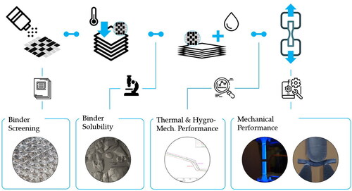
Preforming processes can be used for automated manufacturing of fiber reinforced polymers. Different technologies are used for processing of dry textile fabrics into 2D or 3D preforms. Due to missing tack of dry fabrics, auxiliary binder systems are used for fixation of the fabrics onto a substrate material and in order to achieve sufficient adhesion between layers. In this study, seven reactive and non-reactive tackifying agents have been dissolved in neat resin samples of three epoxy resin systems, showing different degrees of solubility and a variation on neat resin tensile properties (ΔσAVG = 20%) as well as a reduction on thermal properties (up to ΔTg = −18 °C). Subsequently, fiber reinforced polymers were manufactured using Liquid Resin Infusion techniques in order to characterize the influence of binder systems on water absorption (cs,max = 1.38 wt%) and Interlaminar Shear Strength (ILSS). It was shown that ILSS properties are negatively affected by non-reactive tackifying agents (up to −27%).
Graphical Abstract
1. Introduction
Fiber reinforced polymers (FRP) are manufactured by embedding man-made (e.g. glass fibers; carbon fibers, etc.) or natural reinforcement fibers (e.g. flax fibers, hemp fibers, etc.) in a polymer matrix system. In order to accommodate for the applied loads, fibers are aligned in pre-defined fiber orientations and quantity. The use of continuous fiber reinforced composites and their superior weight-specific mechanical properties allows for the engineering of tailored materials, while keeping them lightweight at the same time. As a result of these potentials, fiber-reinforced polymer composites are used in the aerospace, automotive, transport, and construction sectors [Citation1]. Liquid Resin Infusion (LRI) and Out-of-Autoclave (OoA) processes in general have become a popular manufacturing alternative to the cost-intensive autoclave procedure, in order to meet the growing demand for high performance composite components in various industries [Citation2, Citation3]. Within the majority of these processes, low-viscosity, thermosetting matrices are utilized to impregnate dry fiber preforms. In both manual and automated composite preforming processes several layers of dry reinforcement fabrics are stacked, according to a predefined stacking sequence. In order to achieve the optimal mechanical performance in the final composite part, fiber orientations of the reinforcement fabrics have to be precisely met and maintained. Automated manufacturing technologies respectively reduce the risk of fiber misplacement and manual rework [Citation4, Citation5] and a variety of different automated fiber deposition technologies are available, in order to produce load-path oriented and near-net shape preforms [Citation6]. Especially, the Dry Fiber Placement (DFP) technology has recently gained increasing interest throughout the various industrial sectors, due to its high material properties, flexibility and the possibility of producing composite components with low fiber undulations and reduced fiber areal weights (FAW) [Citation7].
1.1. Preforming processes – state of the art
In the context of composite lightweight engineering, one can distinguish between prepreg and preforming manufacturing methodologies. While the automated manufacturing of composite components with unidirectional (UD) pre-impregnated semi-finished products will lead to homogenous and superior part quality, due to reduced undulation and a high fiber volume fraction, the automated processing of UD prepreg materials is also linked to high capital investment, such as autoclave and automated processing technologies, as well as refrigerated storage capacities. However, for the majority of industries, in which composite materials are relevant, processing of dry fibers and fabrics with subsequent resin impregnation is of increasing interest, due to various benefits, such as higher design freedom and material flexibility (a.o.). According to the literature, a preform is defined as a non-impregnated fiber structure with a given orientation and load-path oriented fiber alignment results in a near-net-shape geometry [Citation8]. It can be stated that methodologies for preform manufacturing are divided into direct and sequential processes [Citation8]. Direct preforming processes generally create three-dimensional geometries and integral structures [Citation9] and the utilization of auxiliary binder systems is not necessarily required. Among others, radial braiding [Citation10], 3D weaving, Tailored Fiber Placement (TFP) [Citation11, Citation12] are some of the most common direct preforming methods for continuous FRPs. During sequential preforming, layers of semi-finished products are initially cut to size and subsequently stacked, according to a predefined ply book and the fixation or joining of the layers can be realized using embroidery or binder technology [Citation13]. When using the embroidery technology, the stacked layers are formed into a near-net-shaped geometry and are fixed together with a sewing yarn [Citation14]. When using tackifying agents for layer fixation, an auxiliary material is placed in between two adjacent textile layers. The stack is then heated upon the activation temperature of the auxiliary binder system and consolidated into shape (e.g. hot pressing). After adequate consolidation and removal from the draping process, the preforming step is finalized and ready for subsequent processing and resin impregnation.
One preforming approach, which is recently acquiring increasing relevance is the Dry Fiber Placement process, as a subcategory of the Automated Fiber Placement (AFP) process [Citation15]. This is due to the fact of minimized scrap rates and the possibility to produce load-path oriented fiber orientations within a preform. Most commonly, robotic AFP systems are used for deposition of spread or slit fiber materials. Generally, it can be distinguished between the layup of pre-impregnated tape materials (AFP), thermoplastic tapes (TAFP) [Citation16] and the deposition of spread, non-impregnated but bindered semi-finished products (DFP) [Citation17]. Based on the presence of matrix material in prepreg and thermoplastic semi-finished products during AFP and TAFP, tape fixation is realized due to the adhesive behavior of the matrix material after thermal heat input [Citation18]. Dry fiber materials on the other hand do not possess an inherent tack and auxiliary tackifying agents are required for fiber fixation [Citation19]. Due to the growing interest in DFP processes and its industrial application the availability of bindered tow materials with different tackifying agents has increased. In previous studies it was shown that preform and composite properties can be affected by fiber placement processes [Citation2, Citation20]. Furthermore, Grisin et al. [Citation21] have described the manufacturing of fixedTow [Citation22] and bindered materials [Citation23]. In general, it can be stated that binder technology and its application in sequential preforming processes is critical for high-performance composite components and was therefore subject of numerous studies.
1.2. Impact of binder systems on composite performance
Various authors have studied the effects of tackifying agents on the impregnation behavior of preforms as well as the resin rheology and mechanical performance of fiber reinforced plastic components, mainly driven by matrix-dominant properties. Ringwald [Citation24] and Shih et al. [Citation25] state that the activation process of tackifying agents, in particular the effect of activation temperature, consolidation pressure and duration, can affect the preform permeability. Shih et al. [Citation25] state that inadequate binder activation (e.g. insufficient activation temperature or duration) or excessive amount of binder material [Citation26] will lead to accumulation of binder material in the interface region between two adjacent reinforcement layers, leading to a blockage of resin flow channels, hence affecting the corresponding mechanical behavior of the composite laminate. On the other hand, Dickert et al. [Citation26] report that the presence of tackifying agents can cause a spacing effect within a preform, resulting in enhanced permeability by the creation of macroscopic flow channels. However, this effect is strongly dependent on the binder particle size [Citation26, Citation27]. Additional studies on the solubility behavior of different powder binders and their effect on rheological effects have been studied by Schmidt et al. [Citation28] and Brody [Citation29], showing different degrees of binder solubility. The tensile strength of composite components is dominated by the tensile properties of the reinforcing fibers. For that reason, studies on tensile composite properties in regards to the effects of binder system are rare and it has been shown that binder systems have little effect on composite tensile properties [Citation28, Citation30, Citation31]. Considering compression properties, various authors have come to different conclusions. Schmidt et al. [Citation28] have shown that the compression modulus in fiber direction is increased by the presence of binder systems and compression strength is increased with elevated binder fractions. Tanoglu and Seyhan [Citation32] on the other hand point out that with elevated binder fractions (≤ 3 wt%) compressive behavior is reduced, which is supported by the findings of Geßler et al. [Citation30]. Schulz et al. [Citation33] have investigated the bending properties of composite laminates with a variety of different tackifying agents (Binder Areal Weight (BAW): 4–10 wt%.). It was shown that bending modulus and strength were reduced by 10–15 wt% by all of the binder systems tested. The interlaminar shear strength (ILSS) is a quality criterion, which describes the adhesion of adjacent layers within a composite part. The ILSS test acc. DIN EN ISO 14130 is a measurement of the resistance of composite laminates under shear forces parallel to the layers of the laminate and thus the adherent interface. Since tackifying agents are placed exactly in between two adjacent layers, it can be assumed that the binder system has a major effect on these properties. Shih and Lee [Citation25] have analyzed the impact of the PT500 binder on ILSS properties (resin PR500). For common binder fractions (5–10 wt%), ILSS values show no significant difference to the reference specimens, which is supported by the findings of Girdauskaite [Citation34], while Hillermeier and Seferis [Citation35] state that the use of PT500 led to a reduction of mechanical properties (BAW: 5.7 wt%; resin RTM6). Further studies have been carried out by Brody and Gilespie [Citation29], Tanoglu [Citation36] as well as Bulat et al. [Citation37]. All authors conclude that the application of auxiliary tackifying agents will lead to reduced mechanical properties.
1.3. Scope
The various studies concerning the different effects of tackifying agents reveal that the utilization of auxiliary binder systems need to be carefully addressed in order to achieve adequate composite performance. The main aim of this study is to investigate further thermal and mechanical effects of a variety of different binder systems used in different preforming processes. The majority of past studies have focused on the direct comparison of two binder materials with similar physical appearance (e.g. particulate tackifying agents). Novel tackifying agents, such as SAERfix EP or EPIKOTE MGS PR685, have not been addressed in recent scientific studies so far. However, due to the lack of thermal binder activation processes for SAERfix EP and EPIKOTE MGS PR685, reduced application and handling complexity as well as resin compatibility, those two tackifying agents are of high practical relevance and were thus considered in this study. Furthermore, the commonly used binder system AIRTAC 2E was also not analyzed within previous studies. Therefore, this study includes the analysis of seven reactive and non-reactive binder types with different binder formats, including three powder binders, one textile veil, one adhesive film, one hot-melt-binder and one spray adhesive, as it can be seen in , including novel tackifying agents. Next to their physical appearance, the tackifying agents can be distinguished by means of their chemical composition, activation temperature and their field of application. For that reason, binder solubility was analyzed at distinct curing temperatures, using three different epoxy resins. The selection of the amine cured epoxy resins was based on their specific curing cycles and respective glass transition temperatures (Tg). Therefore, the impact on the glass transition temperature was studied using Differential Scanning Calorimetry (DSC). Additionally, water absorption and its impact on the ILSS behavior was studied and compared to non-conditioned specimens. Finally, tensile testing of neat resin binder samples was carried out.
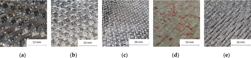
Figure 1. Tackifying agents; (a) Powder binder, e.g. E5390; (b) Textile veil, e.g. PA1541; (c) Adhesive film, e.g. SAER; (d) Hot-melt binder, e.g. PR685; (e) Spray adhesive, e.g. AIR2E.
2. Materials and methods
2.1. Materials
2.1.1. Fabrics
HEXForce G0827 BB1040 [Citation38] carbon fabric was purchased from HEXCEL Composites SASU (Dagneux, France). It is a unidirectional plain weave fabric with a fiber areal weight of 160 g/m2, containing 3k TORAYCA FT300B carbon fibers (198 tex, density: 1.76 g/cm³) in warp direction (97 wt.%) and EC5 5.5 × 2 glass fibers in weft direction (3 wt.%).
2.1.2. Tackifying agents
lists seven different binder systems, which were considered for further assessment. The selection of tackifying agents was based on the criteria listed in Section 1.3 and shall therefore cover a wide range of application. Reactive tackifying agents are based on Bisphenol A and can therefore participate in the cross-linking of the selected epoxy resins due to their similar chemical composition. Non-reactive tackifying agents are composed from a different polymeric material (e.g. a thermoplastic copolyamide) and will therefore not participate in the cross-linking process.
Table 1. Description of tackifying agents characterized within this study.
EPIKOTE 05311 [Citation39], EPIKOTE 05390 [Citation40] and Araldite LT3366 [Citation41] are supplied as white powder with varying grain size distributions (E5311: 90–125 µm; E5390: 50–90 µm; LT3366: 160–200 µm) [Citation22]. Spunfab PA1541 [Citation42] was purchased as a copolyamide veil from Spunfab Ltd. (Cuyahoga Falls, USA) with a binder areal weight of 13 g/m2. The self-adhesive veil SAERfix EP [Citation43] was purchased from SAERTEX GmbH (Saerbeck, Germany). SAERfix EP is compatible with epoxy resins due to chemical cross-linking in the course of curing. HEXION EPIKOTE Resin MGS PR685 [Citation44] is a high-viscous resin component, based on Bisphenol A. At room temperature PR685 shows a high viscosity (≫ 30 000 mPas). For application, the binder has to be heated up in a pneumatic hot-melt glue gun BÜHNEN HB700 K spray from Bühnen GmbH (Bremen, Germany) [Citation45] and is applied at elevated temperatures above 100 °C (2000–3200 mPas). AIRTAC 2E [Citation46] was purchased from AIRTECH Europe Sàrl (Haneboesch, Luxembourg) and is a rubber-based spray adhesive for temporary fixation of consumables and fabrics. AIRTAC 2E is commercially available in aerosol cans and is tacky at room temperature (RT) once the solvents have evaporated.
2.1.3. Resin systems
EPIKOTE Resin MGS RIMR135 and the corresponding hardener EPIKURE Curing Agent MGS RIMH137 from HEXION GmbH (Esslingen, Germany) [Citation47], Biresin CR120 with the hardener Biresin CH120-6 from SIKA AG (Bad Urach, Germany) [Citation48] and Resoltech 1500 with the hardener 1504 from Resoltech Advanced Technology Resins (Rousset, France) [Citation49] are considered for further characterization. Those three low-viscosity, amine curing epoxy resins are suited for LRI processes. Mixing ratios are stated in the respective technical data sheets (TDS) and are identical for all resins with 100:30 ± 2 wt.% (resin: hardener). Curing was accomplished within 24 h at room temperature, followed by resin-specific post-cure cycles according to the respective TDS ().
Table 2. Curing cycles applied for different epoxy resins.
2.2. Manufacturing of neat resin specimen
In order to analyze the solubility of tackifying agents within different epoxy resins, neat resin (NR) samples were produced with a binder fraction of 5 wt%. Neat resin samples of 10 g were manufactured and binder fractions were subsequently added and manually stirred for 3 min at room temperature. A pipette is used for extraction of a resin drop, which is applied onto a slide for subsequent microscope analysis. The aforementioned procedure is not applicable for all binder types, since AIRTAC 2E is supplied in an aerosol can and needs to be sprayed into the mixing bucket beforehand. The epoxy sample is poured in afterwards. The samples are degassed for 5 min at 50 mbar absolute pressure and subsequent curing of binder/epoxy resin samples at elevated temperatures was carried out in a convection oven UF260plus from Memmert GmbH (Büchenbach, Germany) [Citation50]. Different samples are cured at varying temperatures. The curing temperature was increased from room temperature to 120 °C in 20 °C increments.
For mechanical characterization of neat resin specimen and the effect of tackifying agents, a binder fraction of 2 wt.% was set. Due to agglomeration effects for PA1541 at a binder fraction of 5 wt%, the binder ratio was reduced to 2 wt% in order to ensure comparability within the NR test series. Mixtures with an overall amount of 100 g were prepared and corresponding fractions of resin, hardener and binder were measured using the digital scale TGD 50-3C [Citation51] from KERN&SOHN GmbH (Balingen-Frommer, Germany). For mixing and homogeneous dispersion of the binder resin mixture, the centrifugal mixer Mazerustar KK-250S [Citation52] from Kurabo Industries Ltd. (Osaka, Japan) was used. For a homogeneous dispersion of binder particles and yarns, the binder was initially dissolved in the resin component using pre-set program 4 [Citation52], which is specified for mixing and degassing. After subsequent addition of the hardener, the neat resin binder mixture was again centrifuged (program 4). The superimposed revolution and rotation of the mixing containers allows simultaneous blending and degassing. Therefore, further degassing was not required.
Mechanical characterization of neat resin samples acc. to DIN EN ISO 527-2 [Citation53] requires specific dog bone specimen with an overall length of 170 mm and a thickness of 4.0 ± 0.2 mm (Specimen Type 1 A). Silicone casting molds were manufactured according to the dimension stated in DIN EN ISO 527-2 using the casting silicon KDSV-25 from R&G Faserverbundwerkstoffe GmbH (Waldenbuch, Germany) [Citation54]. The neat resin binder mixtures were carefully poured into the mold and cured at room temperature. Visual inspection did not indicate pore formation. After RT curing, the specimens were taken from the silicon mold and post-cured according the corresponding TDS using the heating cabinet UF260plus. Grinding of the specimens to the required thickness was carried out using the rotary sander DP-U3 with a granulation of 125.
2.3. Preform manufacturing
Assyt Bullmer Premiumcut ST from Bullmer GmbH (Mehrstetten, Germany) was used for cutting of the G0827 fabric. In order to achieve a specimen thickness of 2 mm for testing of interlaminar shear strength, 12 layers of carbon fabric are required. Tackifying agents were applied manually with a targeted binder areal weight of 5 wt.%, which is considered as industrial standard providing sufficient tack and processability at minimal BAW. Powder binders (E5390, E5311, LT3366) were manually applied using a sieve container and visually checked for homogeneous distribution quality, while SAER and PA1541 were applied with the given binder areal weight and binder distribution. AIR2E and PR685 were manually applied using the given aerosol cans (AIR2E) and a hot-melt glue gun BÜHNEN HB700 K spray. The distribution quality was checked visually. Preform stacks were subsequently activated in the heating cabinet UF260 plus at elevated temperatures (ET) for 20 min (E5311 and PA1541: 110 °C; E5390: 100 °C; LT3366: 200 °C) using a caul plate for consolidation (100 N). For AIR2E, SAER and PR685 no activation at ET was necessary and respective preform consolidation was carried out at RT.
2.4. Manufacturing of CFRP specimen via LRI
Vacuum Assisted Resin Infusion (VARI) was chosen for resin impregnation of the preform materials and the VARI setup can be seen in . During VARI processing, the resin pot is generally left at atmospheric pressure (approx. 1 atm), while the resin outlet is connected to the vacuum vent. Once the resin inlet is opened, the resulting pressure gradient within the VARI setup draws the resin through the preform.
Figure 2. Manufacturing of CFRP specimen via LRI (a) Schematic VARI set-up (b) Experimental VARI-setup.
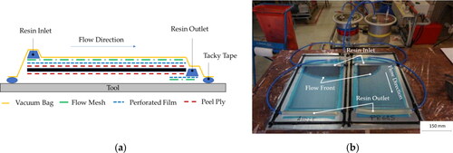
Resoltech 1500 and the corresponding hardener 1504 from Resoltech Advanced Technology Resins (Rousset, France) were used for the manufacturing of the CFRP specimens and were manually mixed according to the respective mixing ratio. The resin-hardener mixture was degassed for 5 min at 11 mbar absolute pressure prior to RT infusion. Ambient conditions were recorded and documented at all times (25.2 °C; 42.5% rH; 964 hPa). After successful infusion of the CFRP specimens (330 mm x 240 mm x 2 mm), curing was carried out at room temperature conditions for 24 h. Subsequent post-curing was executed according to the corresponding TDS at 3 h at 50 °C, 3 h at 100 °C and 3 h at 150 °C. Different samples for mechanical testing were cut on a water-cooled rotary saw (DIN EN ISO 14130 [Citation55]). Conditioning (DIN EN ISO 175 [Citation56]) and fiber volume determination were carried out according to DIN EN 2564 [Citation57] ().
Table 3. Description of CFRP specimen.
2.5. Microscopic analysis
For microscopic analysis of specimen cross-sections and neat resin samples, they were first embedded in Epofix Resin from Struers GmbH (Willich, Germany). Grinding and polishing was carried out on the rotary sanding machine Tegramin30 [Citation58] (Struers GmbH, Willich, Germany). Water-based wet grinding was done with the grinding disc MD-Gekko and varying SiC films (120; 220; 320), while polishing was done with diamond suspension DiaPro Allegro 9 μm and DiaPro Dac 3 μm (Struers GmbH, Willich, Germany) on different polishing discs MD Largo and MD Dac. Final surface finish was done with a Si-Suspension OPS Non Dry and a rotary polishing cloth MD Chem from Struers GmbH (Willich, Germany). Inbetween the different grinding and polishing steps, the samples were cleaned in a water-based ultrasonic bath Emmi 20 HC [Citation59] from EMAG Technologies (Mörfelden-Walldorf, Germany). Micrographs were obtained using the Metallux 3 stereo metallurgical microscope from Ernst Leitz Wetzlar GmbH (Wetzlar, Germany).
2.6. Differential scanning calorimetry (DSC)
In this study, the effects of different tackifying agents on thermal properties were analyzed via Differential Scanning Calorimetry. With the help of calorimetry, the heat quantity is analyzed that is necessary for physical or chemical transformation of a material and can be used for determination of the glass transition temperature Tg. The temperature range in which the transition occurs is called glass transition area and starts at the Onset Point (TOnset). Tg and TOnset are both dependent on the chemical structure as well as the degree of cross-linking. The three epoxy resins RIM 135/RIMH137, Biresin CR120/CH120-6 and Resoltech 1500/1504 were used for DSC analysis. According to Section 2.2 different binder materials with a binder fraction of 5 wt% have been added and the specimens have been cured in a convection oven Memmert UF260 Plus with the corresponding cure cycle. Six DSC samples for every binder resin mixture and the neat resin have been prepared with a sample weight of 12 mgs. Differential Scanning Calorimetry analysis has been carried out using the DSC2920 from TA Instruments (NewCastle, USA). In order to delete the thermal background, two DSC cycles from room temperature to 180 °C at a heating rate of 10 °C per minute are executed with a cooling cycle at 20 °C per minute in between. For the determination of the Tg, the second DSC cycle was analyzed using the half height analysis algorithm.
2.7. Water absorption test
In order to analyze the effect of binder systems on water absorption and the potential degradation of mechanical properties, FRP specimens were conditioned in distilled water according to DIN EN ISO 175. Prior to water storage, the specimens were conditioned at 50 °C for 24 h, cooled within an exsiccator for 3 h and the initial mass m1 was documented with a digital scale TGD 50-3C from KERN&SOHN GmbH (Balingen-Frommer, Germany). Every 24 h the specimens were extracted from the water bath and the corresponding mass mi was documented until no further water absorption was evident (saturation). For analysis of the water absorption, three specimens per FRP batch were measured and the average value was determined.
2.8. Mechanical testing
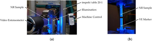
The tensile properties of the neat resin binder samples were evaluated according to DIN EN ISO 527-2 using the tensile testing machine Hegewald & Peschke Inspekt table 20-1 and the corresponding software LabMaster from Hegewald & Peschke Meß- und Prüftechnik GmbH (Nossen, Germany) was used for data documentation and visualization with a measuring resolution of 50 Hz. Each specimen type was tested at least six times. For strain measurement a video extensometer (VE) with a telecentric objective (focal length 334 mm) was used (see ). Testing speed was set to 1 mm/min according to DIN EN ISO 527-2.
Figure 3. Tensile testing of neat resin samples acc. DIN EN ISO 527-2 (a) Test set-up (b) Detailed view of valid test specimen.
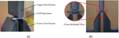
Interlaminar Shear Strength testing was carried out for composite samples according to DIN EN ISO 14130 using the Hegewald & Peschke Universalprüfmaschine Inspekt table 20-1 (Hegewald & Peschke Meß- und Prüftechnik GmbH, Nossen, Germany) testing machine with a set traverse speed of 1 mm/min. A minimum of 6 samples were tested for dry and conditioned specimens (see ). For determination of the interlaminar shear strength the first maximum Fmax,1 of the load curve is used within EquationEq. (1)
(1)
(1) , with a given specimen width
and thickness
according to DIN EN ISO 14130.
(1)
(1)
Figure 4. ILSS testing acc. DIN EN ISO 14130 (a) Test set-up before load application (b) Detailed cross-sectional view.
3. Results and discussion
3.1. Binder solubility
Micrographs for every resin/binder combination were analyzed at different curing temperatures. Representative micrographs can be seen in and . Due to comparable solubility behavior, LT3366 was chosen as characteristic illustration for powder binder solubility (). The same applies to the solubilities for SAER and PR685, for which PR685 was chosen as characteristic illustration and can be seen in . E5311 does not dissolve at room temperature, as a high quantity of binder particles can be detected in the micrographs. With increasing temperature, the number of visible particles is significantly reduced and particle edges rounded. At elevated temperature at 120 °C nearly no residue is apparent. Best solubility can be seen in the Resoltech resin. At 60 °C only few particles are left and vanish at 120 °C. E5390 shows similar behavior. At room temperature binder particles can be detected. When the curing temperature is increased, the remaining particles decrease and at 120 °C the binder is completely dissolved within the epoxy resins. LT3366 does not dissolve at room temperature, as it can be seen in . Particle edges can be seen in every epoxy resin mixture. At elevated temperatures (60 °C) first changes in appearance are obvious. Less particles can be detected and edges are rounded. At 120 °C this observation is even more evident, since only few particles remain in the resins. Furthermore, a halo around the particles is visible. It is assumed that the halo results from dissolved binder. The self-adhesive veil SAER is compatible with epoxy resins and supposed to participate in the chemical cross-linking during the curing process. At elevated temperatures, these binder fragments completely dissolve in the resins, so that no residue is detectable. PR685 is a hot melt binder, consisting of a high viscous resin component only and is supposed to participate in the chemical cross-linking. Micrographs at RT and elevated temperatures reveal that the PR685 shows good solubility in all epoxy resins (). The fact that even at RT no binder residue is apparent confirms that the PR685 participates in the chemical crosslinking.
Figure 5. Reactive binder solubility analysis (a) LT3366 (b) PR685.
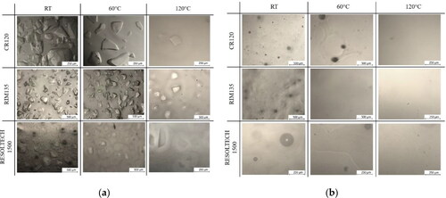
Figure 6. Non-reactive binder solubility analysis (a) PA1541 (b) AIR2E.
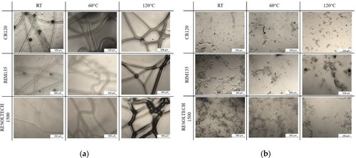
The non-reactive, thermoplastic binder veil PA1541 is not expected to dissolve in the neat epoxy resin samples. When looking at the micrographs () the assumption is verified. No dissolution can be observed at room temperature or at elevated temperatures. Especially at RT and 60 °C a clear outline of the veil structure is evident. The micrograph at 120 °C shows a slight difference in appearance.
Similar to PA1541, the spray adhesive AIR2E is expected not to dissolve in the neat resin samples due to its rubber-based composition. As it can be seen in the micrographs () at RT and ET, the AIR2E does not dissolve or change its appearance in any of the three epoxy resins.
For the assessment of binder solubility, a distinction in four different degrees of solubility is selected, based on morphological changes in the binder residue. Solubility implies that no or only few particles or binder residue are visible in the micrographs at room temperature, as it can be seen for SAER and PR685 (). Solubility for PR685 was expected within the RIM135 resin. Both, tackifying agent as well as epoxy resin, are provided from HEXION GmbH. The TDS of PR685 states that the binder consists of a high-viscous resin component only and is especially suitable for dissolution in HEXION’s LRI matrix systems [Citation44]. However, this study reveals that PR685 is also well soluble within other amine curing epoxy resins, such as CR120 and RES1500. Partial solubility states that after heat application/curing at elevated temperatures binder particles disappear or the quantity of particles is significantly reduced, as it can be seen for E5311 and E5390. Binder materials can be classified as critically soluble, when particle edges are clearly rounded and the remaining quantity of particles in the micrograph is reduced at elevated temperature, as it can be seen for LT3366. Insolubility states that even at elevated temperatures binder residue are still clearly detectable in the neat resin sample, e.g. PA1541 and AIR2E (). The thermoplastic threads of PA1541 at elevated temperatures (e.g. 120 °C) appear wider and not as sharp as in the graphs with lower temperature. This can be explained by the melting temperature of PA1541, which lies between 87 and 100 °C. These morphological changes can therefore be explained by melting of the veil and not by dissolving in the resins.
3.2. Thermoanalytical characterization
It is to be expected that the neat binder materials and their solubility behavior will have an impact on the thermal properties and the glass transition temperature Tg of the epoxy resins. lists the glass transition temperature of the resin systems used. Benchmark measurement series of six reference samples have been analyzed via DSC for every resin/binder mixture and were used for further comparison. The binder/resin samples are compared against the corresponding neat resin sample to make a statement about the effects of different tackifying agents on the glass transition temperature ().
Table 4. DSC analysis of neat resin samples.
Looking at the effect of the tackifying agents on the thermal behavior of the RIM135 resin it can be stated that all binder systems show only little influence on the Tg behavior with the exception of AIR2E which reduces the Tg to 77.34 °C (ΔTg = −9.06 °C). For the epoxy resin SIKA Biresin CR120/CH 120-6, higher deviations can be observed. The Tg was reduced by approx. 4.5 °C for E5311 and PA1541 and with E5390 and PR685 Tg reduction is about 8.88 °C and 11.87 °C respectively. Highest deviation can be observed from AIR2E with a ΔTg of −17.63 °C leading to an absolute Tg of 103.90 °C. The majority of the reactive and non-reactive binder materials reveal no significant impact on the thermal properties of the Resoltech 1500 resin. As illustrated in and E5311, E5390, LT3366, SAER, PR685 and PA1541 have a minor effect on the Tg with a ΔTg of ±2 °C. The rubber-based spray adhesive AIRTAC 2E reveals a ΔTg of −9.41 °C resulting in a Tg of 131.42 °C.
Figure 7. DSC analysis neat resin samples and effect of tackifying agents.
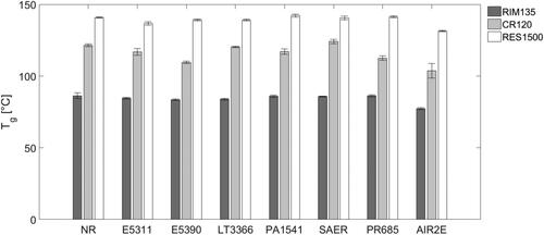
Differential Scanning Calorimetry analysis shows that especially the non-reactive tackifying agent AIR2E significantly affects the thermal properties of all neat resin epoxy samples that have been characterized. An average reduction of ΔTg of −12.04 °C was measured, which might be linked to the non-soluble rubber particles (see ).
3.3. Water absorption
Conditioning in distilled water according to DIN EN ISO 175 of the CFRP specimens covered a period of 49 days. Within the first 10 days, a significant increase of the water content can be noted, which flattens afterwards and reaches a saturated state after approximately another 30–40 days. As it can be seen in , the conditioned specimens with the tackifying agent PR685 has the highest saturated water absorption cs (1.38 wt%), while especially the powder binders E5311 (0.84 wt%), E5390 (0.86 wt%) and LT3366 (0.79 wt%) show a reduced water content, when compared to the neat resin sample (1.01 wt%). lists relevant parameters, such as saturated water absorption cs, diffusion coefficient D (acc. EquationEq. (2)(2)
(2) ) and time until saturation TM∞, which were obtained according to Fick’s Law.
(2)
(2)
Figure 8. Conditioning acc. DIN EN ISO 175 of 8 different CFRP specimens.
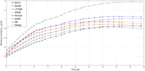
Table 5. Water absorption test analysis acc. Fick’s Law.
The analysis of the water absorption test reveals that particulate tackifying agents exhibit reduced saturated water absorption cs. The punctual application pattern of powder binders results in a non-closed binder surface, therefore the diffusion is reduced, when compared to other bindered specimens. On the other hand, the thermoplastic binder veil PA1541 exhibits a continuous web of thermoplastic yarns, as it can be seen in , which causes enhanced water diffusion within the interlayer area. The enhanced saturated water absorption of PR685 might be caused by the enhanced binder fraction and should be analyzed in future studies. The rubber-based spray adhesive AIR2E does not participate in the chemical cross-linking of epoxy resins. Therefore, binder residue will remain within the interlayer region of the FRP specimens. When compared to particulate tackifying agents, the moisture uptake of AIR2E specimens is enhanced and might be caused by the dense surface coverage of the AIR2E binder application (see ).
3.4. Neat resin characterization
and reveal that the tensile strength of neat resin samples is significantly affected by the presence of auxiliary binder systems. The highest impact can be observed, when powder binders are dispersed to the neat resin mixture. Especially E5390 leads to highest reductions of the tensile strength for CR120 (−52.29%) and RES1500 (−41.82%), while LT3366 leads to significant reduction for RIM135 (−45.48%). When assessing the tensile strength of RIM135 it can be noted that the tackifying agents AIR2E, PA1541, PR685 and SAER barely affect the mechanical properties. For CR120, similar results can be observed for AIR2E and PR685, while for RES1500 the tackifying agents SAER and AIR2E show no significant impact. When addressing the elongation at break in , similar observations can be found. Especially powder binder systems seem to affect the fracture strain for all neat resin samples the most. In general, it can be stated that binder systems seem to shift the fracture behavior to a more brittle fracture behavior. Similar findings were observed by Schmidt et al. [Citation28]. The brittle behavior can be explained due to non-dissolved binder residue within the neat-resin samples. These inhomogeneities will lead to local mechanical property gradients and a reduced elongation at break. The E-Modulus is the property which is least affected by tackifying agents. The E-modulus is captured from the gradient between 0.05 and 0.25% elongation. In this area, barely any effects are detected, as illustrated in .
Figure 9. Ultimate tensile strength acc. DIN EN ISO 527.
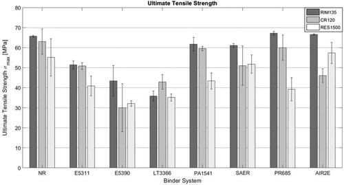
Figure 10. Elongation at break acc. DIN EN ISO 527.
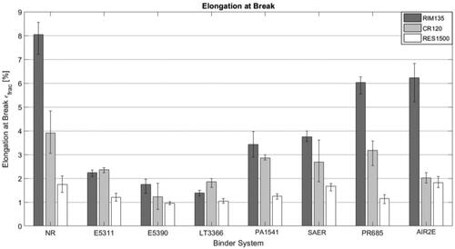
Figure 11. Young’s modulus E of neat resin samples and effect of tackifying agents.
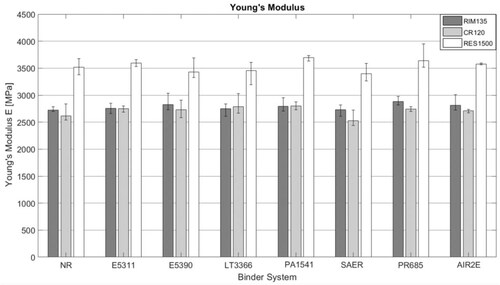
Table 6. Analysis of neat resin tensile properties acc. DIN EN ISO 527.
3.5. Composite characterization
The assessment of interlaminar shear strength for composite laminates was carried out according to DIN EN ISO 14130. ILSS values were measured in both, dry and conditioned state and are compared in . Conditioning was carried out in order to assess the influence of water absorption on the mechanical properties. The majority of load curves show a significant drop in force, which indicates a shear failure within the layers of the composite laminate and therefore a reduction of ILSS properties. However, the load curves of PR685 and PA1541 did not show distinct drops in load, which leads to a higher standard deviation. Based on manual application with a pneumatical hand device, precise dosing of PR685 was not feasible. Due to the elevated binder content in the PR685 samples (BAW ∼ 15 wt%), a direct comparison is not valid. However, this finding reveals that for industrial application of binder technology within structural high-performance components, adequate dosing technology is a decisive factor in order not to compromise the mechanical composite properties, which is supported by further studies [Citation60].
Figure 12. Graphical ILSS assessment acc. DIN EN ISO 14130.
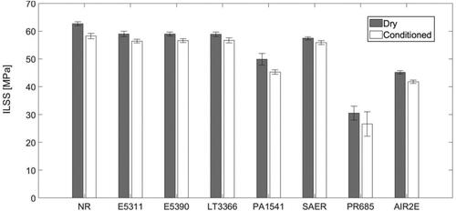
As illustrated in , the presence of tackifying agents leads to a reduction of ILSS properties for all binder systems which have been assessed. Powder binder systems and SAER seem to have a minimal effect on interlaminar shear strength. PA1541, PR685 and AIR2E significantly affect the ILSS properties, while PR685 leads to highest reductions. It needs to be stated that for PA1541 the highest absolute loads have been recorded. The fact that PA1541 leads to an increase in specimen thickness, results in reduced shear stress values. Moreover, it needs to be mentioned that the overall binder amount for PR685 is elevated (∼15 wt%), therefore it is reasonable to assume that the reduced ILSS values are due to the elevated binder fraction. also shows that the ILSS properties for conditioned specimens are reduced for all binder systems that have been analyzed. In general, ILSS values are reduced between 2 and 5 MPa, when conditioned in distilled water acc. DIN EN ISO 175.
Table 7. ILSS assessment acc. DIN EN ISO 14130.
In general, it can be stated that no correlation between the neat resin properties (Section 3.4) and the ILSS properties was identified.
When the ILSS properties between reactive and non-reactive binder materials are distinguished, a clear tendency can be observed. In average reactive binder agents lead to a reduction of ILSS values by 6.59% (10.06% after conditioning), while non-reactive tackifying agents cause a reduction of ILSS by 24.17% (30.52% after conditioning). Similar findings have been observed by other authors [Citation29, Citation35, Citation37, Citation61, Citation62]. The significant reduction of ILSS properties of non-reactive tackifying (PA1541 and AIR2E) agents can be explained due to the present binder residue within the interlayer region of the ILSS specimens. The continuous thermoplastic veil PA1541 and the areal application of AIR2E lead to inhomogeneities that enhance microcracking and furthermore promotes moisture absorption, which further reduces ILSS properties upon conditioning.
4. Conclusions
In the present study, different reactive and non-reactive tackifying agents and their respective effect on composite performance has been studied. Binder solubility in three different epoxy resins was studied via micrograph assessment, indicating solubility for reactive tackifying agents, especially at elevated temperatures. For PR85 and SAER solubility was also verified at room temperature. For the non-reactive tackifying agents PA1541 and AIR2E no solubility was evident at both, room temperature and elevated temperature. Thermal properties have been analyzed via Differential Scanning Calorimetry, revealing that the non-reactive tackifying agent AIR2E reduces the glass transition temperature of all epoxy resins (RIM 135: −9 °C; CR120: −18 °C; RES1500: −9 °C). Furthermore, the water absorption of cured CFRP specimens was analyzed according to DIN EN ISO 175 and it was shown that all specimens reach saturation at approximately 1 wt%, while PR685 leads to elevated water absorption (∼ 1.4 wt%). Additionally, the effect of the different binder systems on neat resin mechanical properties was analyzed according to DIN EN ISO 527, indicating that tensile strength was reduced for the different powder binder systems (E5311, E5390 and LT3366). Similar behavior was observed for elongation at break and it can be stated that for all tackifying agents assessed, the fracture behavior shifts to a more brittle behavior. Ultimately, interlaminar shear strength (ILSS) was studied according to DIN EN ISO 14130. It was evident that PA1541, PR685 and AIR2E led to a significant reduction of the ILSS properties. Similar behavior was found for conditioned specimens, while all of the conditioned specimens exhibit slightly reduced properties.
Conclusively, it can be noted that both reactive and non-reactive tackifying agents affect composite performance, while non-reactive tackifying agents seem to have a higher impact. Especially, the utilization of AIR2E should be reconsidered in high-performance composite applications, due to significant impacts in thermal and mechanical properties.
In order to minimize the decline of thermal and mechanical properties of composite components, the binder fraction during preform processes has to be reduced to a minimum. Another possibility for binder effect reduction is the appropriate selection of a tackifying agent according to the resin system being used. Furthermore, the selective in-line application of binder systems during preforming processes could result in superior overall composite performance. However, the resulting local property gradients and their effects on overall composite performance need to be studied in detail.
Disclosure statement
No potential conflict of interest was reported by the authors.
Data availability statement
The data that support the findings of this study are available from the corresponding author, FH, upon reasonable request.
Additional information
Funding
References
- Szcesny M, Heieck F, Carosella S, et al. The advanced ply placement process – an innovative direct 3D placement technology for plies and tapes. Adv Manuf Polym Compos Sci. 2017;3(1):2–9.
- Aziz AR, Ali MA, Zeng X, et al. Transverse permeability of dry fiber preforms manufactured by automated fiber placement. Compos Sci Technol. 2017;152:57–67.
- Meinhardt T, Harismendy I, Heieck F. LOWFLIP – tailored Snap-Cure prepregs for novel composite production processes. Proceedings of the 17th European Conference on Composite Materials 2016, Munich, Germany, June 26–30th, 2016.
- Nguyen MH, Vijayachandran AA, Davidson P, et al. Effect of automated fiber placement (AFP) manufacturing signature on mechanical performance of composite structures. Compos Struct. 2019;228:111335.
- A roadmap to automated composites. [cited 2022 Jan 25]. https://www.cgtech.com/images/pdf/Roadmap-to-Automated-Composites.pdf.
- Björnsson A. Enabling automation of composite manufacturing through the use of off-the-shelf solutions [PhD thesis]. Linköping (Sweden): Linköping University, 2014.
- Composites World. [cited 2022 Jan 25]. https://www.compositesworld.com/articles/dry-fiber-placement-surpassing-limits
- Cherif C. Textile werkstoffe für den leichtbau. Berlin (Heidelberg): Springer Berlin Heidelberg, 2011.
- Schnabel A, Grundmann T, Kruse FF, et al. Automatisiertes textiles preforming. Lightweight Des. 2009;2(3):44–47.
- Kyosev Y. Braiding technology for textiles. Waltham (MA): Woodhead Publishing; 2014.
- Schmucker WJ. TFP-RTM-Bindertechnologie in hochbelasteten kohlefaserbauteilen. Lightweight Des. 2010;3(1):38–42.
- Carosella S. Analyse und verbesserung des faserablegeverfahrens tailored fibre placement zur kostenoptimierten preformherstellung. Verl. Dr. Hut, München, 2015.
- Klingele J, Greb C, Linke M, et al. Auftrag und aktivierung von bindern. Lightweight Des. 2011;4(6):54–61.
- Fernández Eguibar D. Selective stitching on composite skin-stiffener bonding for improved damage tolerant structures. Verl. Dr. Hut, München, 2019.
- Lukaszewicz DH-J, Ward C, Potter KD. The engineering aspects of automated prepreg layup: history, present and future. Compos B Eng. 2012;43(3):997–1009.
- Zenker T. T-AFP – Thermoplastic automated fiber placement for the manufacturing of structures. Luftfahrttechnisches Handbuch, 2021, Under Review.
- Veldenz L, Francesco MD, Astwood S, et al. Characteristics and processability of bindered dry fibre material for automated fibre placement, Munich. Proceedings of the 17th European Conference on Composite Materials 2016, Munich, Germany, June 26–30, 2016.
- Schledjewski R, Yadav N. Safe and efficient heating – how to identify the best performing heating method for thermoplastic tape placement. Proceedings of the SAMPE Europe Conference 2019, Nantes, France, September 17–19, 2019.
- Veldenz L, Francesco MD, Giddings P, et al. Material selection for automated dry fiber placement using the analytical hierarchy process. Adv Manuf Polym Compos Sci. 2018;4(4):83–96.
- Croft K, Lessard L, Pasini D, et al. Experimental study of the effect of automated fiber placement induced defects on performance of composite laminates. Compos A Appl Sci Manuf. 2011;42(5):484–491.
- Grisin B, Carosella S, Middendorf P. Dry fibre placement: the influence of process parameters on mechanical laminate properties and infusion behaviour. Polymers. 2021;13(21):3853.
- Helber F, Schrick B, Carosella S, et al. Tailored preform production with customizable UD materials for hybrid material design. Proceedings of the SAMPE Europe Conference 2017, Stuttgart, Germany, November 14–16, 2017.
- Helber F, Szcesny M, Carosella S, et al. Tack and binder solubility investigations on reactive and Non-Reactive binder systems. Proceedings of the SAMPE Europe Conference 2019, Nantes, France, September 17–19, 2019.
- Ringwald H. Entwicklung und charakterisierung von binderaktivierungsverfahren zur herstellung von carbonfaserverstärkten kunststoffen [PhD thesis]. Stuttgart (Germany): München, University of Stuttgart, 2014.
- Shih C-H, Lee LJ. Tackification of textile fiber preforms in resin transfer molding. J Compos Mater. 2001;35(21):1954–1981.
- Dickert M, Berg DC, Ziegmann G. Influence of binder activation and fabric design on the peremeability of non-crimp carbon fabrics. Proceedings of Eleventh Internatinal Conference on Flow Processing in Composite Materials – FPCM11 – Auckland, July 9–12, 2012.
- Rimmel O, Becker D, Mitschang P. Maximizing the out-of-plane-permeability of preforms manufactured by dry fiber placement. Adv Manuf Polym Compos Sci. 2016;2(3–4):93–102.
- Schmidt S, Mahrholz T, Kühn A, et al. Powder binders used for the manufacturing of wind turbine rotor blades. Part 1. Characterization of resin-binder interaction and preform properties. Polym Compos. 2018;39(3):708–717.
- Brody JC, Gillespie JW. Reactive and non-reactive binders in glass/vinyl ester composites. Polym Compos. 2005;26(3):377–387.
- Geßler A. Textile integrationstechniken zur herstellung vorkonfektionierter verstärkungsstrukturen für FVK INTEX. Zusammenfassender Schlussbericht, München, 2002.
- Beier U. High-performance fibre-reinforced composites prepared by a novel preform manufacturing routine [PhD thesis]. Univ. Lehrstuhl für Polymere Werkstoffe, University of Bayreuth, Bayreuth, 2010.
- Tanoğlu M, Seyhan A. Compressive mechanical behaviour of E-glass/polyester composite laminates tailored with a thermoplastic preforming binder. Mater Sci Eng: A. 2003;363(1-2):335–344.
- Schulz J, Kühne E, Wielage B. Einsatz der preformtechniken zur produktivitätssteigerung bei der verarbeitung von faserverbundkunststoffen. Proceedings of the 17. Symposium Verbundwerkstoffe und Werkstoffverbunde, 2009, Bayreuth, Germany, April 1–3, 2009.
- Girdauskaite L, Krzywinski S, Rödel H, et al. Local structure fixation in the composite manufacturing chain. Appl Compos Mater. 2010;17(6):597–608.
- Hillermeier RW, Seferis JC. Interlayer toughening of resin transfer molding composites. Compos A Appl Sci Manuf. 2001;32(5):721–729.
- Tanoğlu M, Seyhan AT. Investigating the effects of a polyester preforming binder on the mechanical and ballistic performance of E-glass fiber reinforced polyester composites. Int J Adhes Adhes. 2003;23(1):1–8.
- Bulat M, Heieck F. Binder application methods for textile preforming processes. LTH Faserverbund-Leichtbau, 2014, FL 21 200–02.
- HEXCEL Fibers SASU, Roussillon, France. Product Data Sheet HexForce G0827 BB1040, 2018.
- HEXION Stuttgart GmbH, Esslingen, Germany, Technical Data Sheet EPIKOTETM Resin 05311, 2006.
- HEXION Stuttgart GmbH, Esslingen, Germany, Technical Data Sheet EPIKOTETM Resin 05390, 2006.
- Huntsman Advanced Materials (Switzerland) GmbH, Basel, Switzerland, Technical Data Sheet Araldite® LT 3366, 2011.
- Hänsel Verbundtechnik GmbH, Iserlohn, Germany, Technical Datasheet PA 1541, 2013.
- SAERTEX GmbH & Co. KG, Saerbeck, Germany, Safety Data Sheet SAERfix® EP, 2017.
- HEXION Stuttgart GmbH, Esslingen, Germany, Technical Data Sheet EPIKOTETM Resin MGS PR 685, 2017.
- Bühnen GmbH & Co. KG, Bremen, Germany, Operating Manuel HB 700K Spray, 2008.
- AIRTECH EUROPE Sarl, Differdange, Luxembourg, Safety Data Sheer AIRTAC 2E, 2015.
- HEXION Stuttgart GmbH, Esslingen am Neckar, Germany. Technical Information EPIKOTE Resin, MGS RIMR135, 2014.
- SIKA Deutschland GmbH, Bad Urach, Germany, Product Data Sheet Biresin, CR120, 2021.
- Resoltech Advanced Technology Resins, Rousset, France, Safety Data Sheet 1500, 2020.
- Memmert GmbH, Schwabach, Germany, Product Specification UF260plus, 2021.
- KERN & Sohn GmbH, Balingen, Germany, Operating Manual TGD, 2018.
- KURABO Advanced Technology Division, Osaka, Japan, MAZERUSTAR Catalogue, 2021.
- DIN EN ISO 527-2, Plastics – Determination of tensile properties – Part 2: test conditions for moulding and extrusion plastics. ISO 527-2: 2012.
- R&G Faserverbundwerkstoffe GmbH, Waldenbuch, Germany, Safety Data Sheet Siliconkautschuk. KDSV-25, 2015.
- DIN EN ISO 14130, Fibre reinforced plastic composites – Determination of apparent interlaminar shear strength by short beam-method. ISO 14130, 1997.
- DIN EN ISO 175 ; Plastics – Methods of test for the determination of the effects of immersion in liquid chemicals. ISO 175, 2010.
- DIN EN 2564, Aerospace series – Carbon fibre laminates – Determination of the fibre, resin and void contents. German and English version, EN 2564, 2018.
- Struers GmbH, Willich, Germany, Betriebshandbuch Tegramin-25/-30 (Nr.16037025); revision C, 2018.
- EMAG Technologies, Mörfelden-Walldorf. Germany, Operating Instructions EMMI20 HC, 2019.
- Schmidt S, Mahrholz T, Kühn A, et al. Powder binders used for the manufacturing of wind turbine rotor blades. Part 2. Investigation of binder effects on the mechanical performance of glass fiber reinforced polymers. J Compos Mater. 2019;53(16):2261–2270.
- Tanoglu M, Robert S, Heider D, et al. Effects of thermoplastic preforming binder on the properties of S2-glass fabric reinforced epoxy composites. Int J Adhes Adhes. 2001;21(3):187–195.
- Henning K. Wirtschaftliche Herstellung von Faserverbundbauteilen mit Hilfe automatisiert hergestellter textiler Preforms [PhD thesis]. RWTH Aachen, Aachen, Germany, 2008.