
Abstract
Synthesis of chiral films in chiral liquid crystal is reported. The monomers (3, 3′-hexylsilane-2, 2′-bithiophene and 3,6-bis(3, 4-ethylenedioxythienyl)pyridazine) in cholesteric liquid crystal (CLC) electrolyte solution were elecropolymerised by the application of voltage to yield a thin film. Circular dichroism measurements display the Cotton effect for the films. The polymers show a fingerprint texture very similar to that of the CLC. The structure developed during polymerisation was preserved even after washing. Note that no chiral molecule reacted chemically with the monomer during polymerisation. The electrolyte functioned as a chiral matrix. This simple method can be defined as asymmetric polymerisation in chiral environment.
1. Introduction
Optically active polymers have been synthesised by many approaches, such as substitution of an optically active groups into the polymer.[Citation1–11] Optically active polyanilines were produced by doping of chiral camphor sulfonic acid.[Citation12,Citation13]
Electrochemical polymerisation is an effective method to yield semi-conducting polymers.[Citation14,Citation15] The π-conjugated polymers have been studied with respect to applications in electrochromic devices and as transparent electrodes. The product of the reaction is obtained in the form of a film. The film is adhered on the electrode surface. However, it is difficult to control the higher order structure and macroscopic morphology of the electrochemically synthesised polymer. Furthermore, polymer films synthesised by electrochemical polymerisation do not show optical activities, generally. However, the polymer synthesised by electrochemical polymerisation using cholesteric liquid crystal (CLC) as an electrolyte solution shows CD.[Citation16]
In this study, electrochemical polymerisations of achiral 3,3′ -hexylsilane-2,2′-bithiophene (abbreviated as HMSBT) and 3,6-bis(3,4-ethylenedioxythienyl)pyridazine (BET) are carried out in CLC as an asymmetric matrix to obtain electro-optically active semi-conducting polymer films from achiral monomers.
The addition of small amounts of the chiral inducer helped in the formation of the cholesteric phase with a helical aggregation structure from the achiral nematic liquid crystal phase. In this study, the CLC electrolyte solution is obtained by adding small amounts of the chiral compound of cholesterol oleyl carbonate as a chiral inducer to a large volume of nematic liquid crystal. The liquid crystallinity of the cholesteric LC electrolyte solution has been confirmed to be maintained after the addition of tetrabutyl ammonium perchlorate (TBAP) as a supporting electrolyte, the monomer, and the chiral inducer. The cholesteric LC can be regarded as a solvent because it exhibits fluid properties, and a range of compounds are soluble. The mixture of cholesteric LC solution can be used as an electrolyte for electrochemical polymerisation in place of a normal liquid system such as TBAP in acetonitrile solution.
We perform electrochemical polymerisations of HMSBT and BET in the chiral liquid crystal as an asymmetric matrix. The preparation of CLC containing a supporting salt and monomer, polymerisation of the monomer in CLC, and the characterisation of chiroptical activity are presented.
Scheme. 1. Synthesis of BET for electrochemical polymerisation
2. Experimental
2.1. Techniques
Infrared spectroscopic measurements were carried out using a Jasco 550 Fourier infrared spectrometer. Optical texture observations were made by polarising optical microscopy (POM) using a Nikon ECLIPS E 400 POL polarising microscope equipped with a Linkam TM 600PM heating- and-cooling stage. Temperature control during polymerisation was achieved using a custom-made cooling stage based on a Peltier element. UV–VIS–NIR optical absorption spectra were obtained with a JASCO V-640 (Japan). The CD spectra, optical rotator dispersion (ORD) of the polymers were obtained with a JASCO J-730 (Japan) with the ORD measurement option. Electrochemical doping was performed with the μ Auto Lab III potentiostat (the Netherlands) versus the Ag/Ag+ reference electrode.
2.2. Materials
4-Cyano-4′-n-hexylcyanobiphenyl (6CB) was purchased from Merck Ltd. The indium-tin-oxide (ITO) glass of 9 Ω/cm2 was purchased from Furruchi Chemical (Japan).
2.3. Monomer synthesis
In this study, 3, 3′-hexylmethysilylene-2,2′-bithiophene (HMSBT) and BET were employed as monomers. HMSBT can be prepared by a similar reaction reported by Nakanishi et al.[Citation15]
Reaction between 3,4-(ethylenedioxy)thiophene (EDOT), n-butyllithium, and tributylstannyl chloride was carried out to yield 2-(tributylstannyl)-3,4-(ethylenedioxy) thiophene. A reaction of maleic hydrazide and phosphorus pentabromide gave 3,6-dibromopyridazine. Next, the Migita-Kosugi-Stille coupling reaction between 2-(tributylstannyl)-3,4-(ethylenedioxy)thiophene and 3,6-dibromopyridazine with the aid of [Pd(PPh3)4] allows the production of BET as a monomer ().
2-(Tributylstannyl)-3,4-(ethylenedioxy)thiophene [Citation17]: A solution of EDOT (10 g, 71 mmol) in 80 mL of tetrahydrofuran (THF) was stirred under an argon atmosphere at −78°C. Equimolar amount of n-butyllithium in THF solution was added to the mixture with a pressure equalised funnel, and stirred for 30 min. Then, an equimolar molar amount of tributylstannyl chloride was added to the solution, and stirred for 3 h at room temperature. After the reaction, triethylamine (1.5 mL) and ethanol (20 mL) were added to the solution. The mixture was washed with water thoroughly. After the evaporation, the crude product was purified by column chromatography (silica gel, triethylamine and dichloromethane). Evaporation of the solvents from the mixture and removed unreacted EDOT under reduced pressure yield colourless oil. Y = 15% (4.9 g, 11 mmol). 1H NMR (400 MHz, δ from TMS, CDCl3): 6.57 (s, 1H), 4.16 (m, 4H), 1.62–xu49 (m, 6H), 1.37–1.28 (m, 6H), 1.11–1.06 (m, 6H), 0.89 (t, 9H, J = 7.2 Hz).
3,6-Dibromopyridazine: A solution of maleic hydrazide (0.95 g, 8.5 mmol) and phosphorus pentabromide (4.0 g, 9.3 mmol) were stirred for 2 h at 100°C. After the reaction, the mixture was cooled to room temperature. The reactant was dissolved in dichloromethane and washed with water/NaHCO3. The organic layer was evaporated. The crude product was purified by column chromatography (silica gel, dichloromethane). The material was dried under reduced pressure to yield the desired compound as a white solid. Y = 9.6% (0.19 g, 0.82 mmol). 1H NMR (400 MHz, δ from TMS, CDCl3), 7.53 (s, 2H), 13C NMR (100 MHz,g δ from TMS, CDCl3), 147.6, 133.3.
BET: A solution of 2-(tributylstannyl)-3,4-(ethylene- -dioxy)thiophene (0.65 g, 1.5 mmol), 3,6-dibromopyrida-zine (0.15 g, 0.65 mmol) in toluene (3.0 mL) was stirred at 80°C under an argon atmosphere. Then, the catalytic amount of tetrakis(triphenylphosphine)palladium (0) [Pd(PPh3)4](32 mg, 0.028 mmol) was added to the mixture, and stirred for 24 h at 90°C. After the reaction, the mixture was cooled to room temperature and washed with water thoroughly. The organic layer was extracted with dichloromethane. After the evaporation, the crude product was purified by column chromatography (silica gel, methanol) followed by recrystalisation from ethylacetate. After filtration, the material was dried under reduced pressure to yield the desired compound as a brown solid. Yield = 1.8% (4.2 mg, 0.012 mmol). 1H NMR (400 MHz, d from TMS, CDCl3), 8.05 (2H, m), 7.52 (2H, m), 4.38 (8H, m). TOF-MS, found m/z = 361.02 (M+H)+, calcd for C16H12N2O2S2 360.41.
2.4. Preparation of the chiral electrolyte containing a monomer
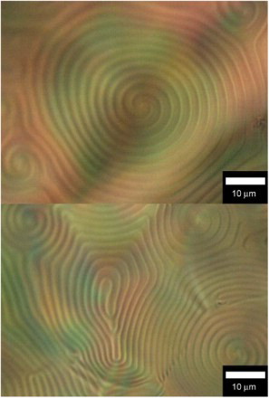
An electrolyte solution of HMSBT (0.9 wt%, monomer), 6CB (89.7 wt%, nematic LC), cholesterol oleyl carbonate (9.0 wt%, chiral inducer) and TBAP (0.4 wt%, supporting electrolyte) were prepared for cholesteric LC electrolyte solution containing monomer. The electrolyte in a vial was heated to ca. 80°C to completely dissolve the contents. (top) shows a POM image of the CLC electrolyte solution containing monomer before polymerisation. The fingerprint texture indicates the formation of cholesteric LC at room temperature. The distance between the stripes in the texture corresponds to a helical half-pitch. This observation confirms that electrochemical polymerisation can be performed at room temperature.
Fig. 1. POM images. (Top) CLC electrolyte solution containing HMSBT as a monomer (before polymerisation). (Bottom) CLC electrolyte solution after the electrochemical polymerisation.
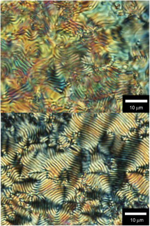
The preparation of the CLC containing BET was also carried out. Quantities used: BET 0.9 wt%, 6CB (88.5 wt%), TBAP (1.8 wt%) (top). Constituents of the electrolyte solutions are summarised in .
Table 1 Chemical structures of the monomers, the nematic LC, the chiral inducer, and the supporting electrolyte.
Fig. 2. POM images. (Top) CLC electrolyte solution containing BET as a monomer (before polymerisation). (Bottom) CLC electrolyte solution after the electrochemical polymerisation.
2.5. Polymerisation
The CLC electrolyte solution containing a monomer was sandwiched between ITO electrodes using a Teflon sheet (thickness ca. 0.1 mm) as a spacer. The CLC mixture was charged into the reaction cell using a capillary technique. The polymerisation cell was heated once to 80°C, and then gradually cooled to room temperature to obtain a good fingerprint texture. A constant voltage of 4 V was then applied to the cell, which did not affect the optical texture of the CLC mixture because the cell gap is wide enough. The surface temperature of the reaction cell was monitored to be 22°C by using a radiation thermometer.[Citation16]
After 20 min, a thin film of the insoluble and infusible blue polymer was deposited on the anode side of the ITO electrode. The film was carefully washed with hexane. The film was then dried. An optical texture of the electrolyte solution after the polymerisation of HMSBT is shown in (bottom). The fingerprint texture indicates that the cholesteric phase was maintained from beginning to finish of the electrochemical polymerisation. The electrochemical polymerisation was successfully carried out in the cholesteric liquid crystalline phase. The POM images of the CLC electrolyte solution containing BET after the polymerisation confirmed the maintenance of liquid crystallinity during the polymerisation of the BET ( (bottom)).
3. Results and discussion
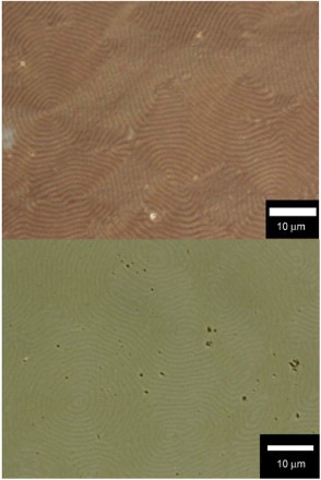
POM images of the polymers film thus obtained in the CLC are shown in ( HMSBT,
BET). The films exhibit fingerprint textures. The fingerprint textures of the polymer thus obtained were imprinted from the CLC electrolyte solution.
Fig. 3. POM image of the polymer film prepared in the CLC electrolyte solution. (Top) poly HMSBT, (bottom) poly BET.
The UV–VIS absorption spectra and CD of the poly HMSBT are shown in . The spectra were obtained by in situ measurements. The film was electrochemically doped or dedoped. The polymer in the reduced form (0 V) and an absorption band at 520 nm were observed due to π–π* transition of the main chain. The main chain absorption band is decreased with an increase in application voltage up to 0.7 V due to electrochemical doping (oxidation). In this case, the perchlorate ions in the acetonitrile solution play a role of accepter dopant and the ion was doped electrochemically to the polymer at certain potentials. The doping (oxidation) level can be tuned by the applied voltage. On the contrary, an absorption band at long wavelengths (>600 nm) is observed due to the generation of charge carrier polarons (radical cations).
Fig. 4. (Top) CD spectra of the polymer at 0–0.7 V. (Bottom) UV–VIS absorption spectra of poly HMSBT at 0–0.7 V.
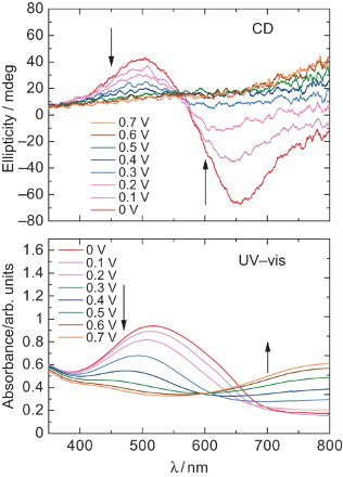
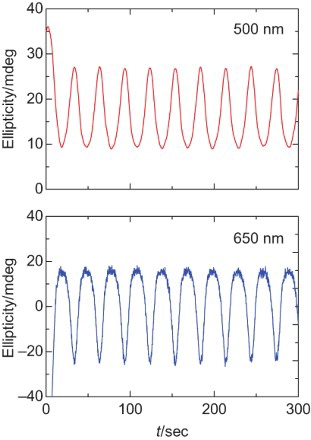
In the CD spectra, a positive signal at 500 nm and negative signal at 600 nm are observed at 0 V. The negative Cotton effect (negative to positive signal from long wavelength) can be due to the Davydov splitting. The splitting comes from the helical structure of the chiral plural chromospheres. The spectral form is changed to a mono-signate positive sign by an increase in the application voltage. This is because the electrochemical doping tunes the helicity of the polymer. The progress of the doping makes partly unwinding of the helical structure accompanied by the generation of polarons as the charge carrier. The polaron in the aromatic type conjugated polymers consists of a planar quinonoid structure. However, the chiroptical activity of the heavily doped polymer still remained, because the polymer in the heavily doped state shows a positive broad signal at the long wavelengths. shows a repeating change in the CD at 500 and 650 nm. This result indicates that repeating the electrochemical doping–dedoping process produces repeating change in the ellipticity. This phenomenon can be referred to as the electro-chiroptical effect. The expected chiroptical activity is not due to the chiral inducer used in this polymerisation because the Cotton effect of the chiral inducer is only observed at shorter wavelengths.
Fig. 5. Repeating change in ellipticity at 500 nm (top) and 650 nm (bottom) of poly HMSBT by applying voltage between 0 and 0.7 V.
This polymer having the chiral-semiconducting property shows electo-chiroptical chromism based on the generation of charge carrier by doping.
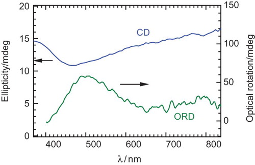
shows UV–VIS absorption spectra of poly BET of the as-prepared form after the polymerisation (doped) and the reduced form. The doped form (as prepared) shows an absorption band of polarons (doping band). The reduced form was prepared from the doped form by treatment with aqueous hydrazine; however, the reduction was incomplete because doping band still appears. Therefore, the reduced form can be of the lightly doped state. The absorption band at short wavelength due to π–π* transition decreased with the reduction process. Although the poly BET shows a fingerprint texture, the polymer exhibits no dynamically absorption change with the application of repeated voltage. This can be due to the fact that the BET as a monomer has no good solubility in the CLC electrolyte solution and low polymerisation activity during the polymerisation, resulting in no steady film being deposited on ITO. However, the poly BET shows chiroptical activity in the reduced form, as shown in . The polymer shows a negative signal in the CD, and positive optical rotation at around 500 nm. The chiroptical activities of the polymer can be confirmed; however, dynamic control by the electrochemical redox process could not be carried out. On the other hand, poly HMSBT shows a consistent change in CD by the electrochemical redox process. These results indicate that the film-forming property and electrical contact of the resultant polymer with the ITO electrode are important to for displaying the electro-chiroptical effect. Poly HMSBT has flexible alkyl chains in the monomer repeat unit. The alkyl-side chain improved the solubility in the CLC. The side chains did not disturb the imprinting process from the matrix CLC electrolyte solution during the electrochemical polymerisation process. Therefore, the structural form imprinting from the CLC was successfully carried out for the polymerisation of HMSBT.
Fig. 6. UV–VIS absorption spectra of poly BET of as prepared form (doped) and reduced form.
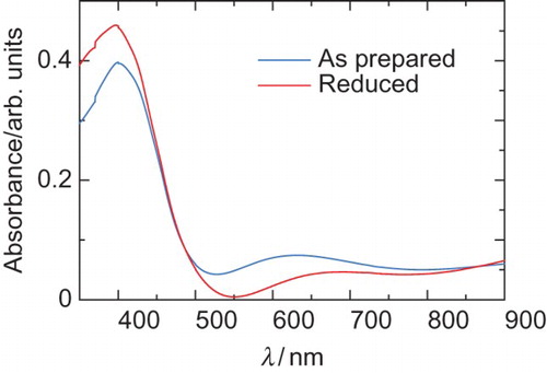
Fig. 7. CD and ORD of the poly BET prepared in CLC electrolyte solution.
4. Conclusions
The polymers form a characteristic morphology that transcribed the liquid crystal aggregation structure. The CLC medium used here provides a chiral pattern as a molecular template during polymerisation, and the polymer grows in the chiral matrix to form a screw structure by the electrochemical polymerisation process. The polymerisation mechanism in this method differs from chiral polymerisation which uses a chiral catalyst. This method, asymmetric electrochemical polymerisation, developed by the author based on the original idea [Citation16] can be defined as ‘matrix imprinting’ in liquid crystals. Furthermore, chiral molecular imprinting (MIP) in the molecular level would have occurred in this polymerisation. This polymer having the ‘chiral-semiconducting’ property shows electo-chiroptical chromism based on the generation of charge carrier.
Notes on contributors
Yusuke Nita received MSci (2014) in chemistry from University of Tsukuba in his native Japan. Hiromasa Goto received his Ph.D. from University of Tsukuba under the supervision of Professor Hideki Shirakawa (2000 Nobel Prize laureate). He was an Assistant Professor at U. Tsukuba (1997). He is a Professor in Graduate School of Pure and Applied Sciences, U. Tsukuba. He has developed synthesis of chiral polymers in liquid crystals since 2000. His current interests are liquid crystals, chiral chemistry, and polymer synthesis.
References
- Langeveld-Voss BMW, Janssen RAJ, Meijer EW. On the origin of optical activity in polythiophenes. J Mol Struct. 2000;521:285–301. doi: 10.1016/S0022-2860(99)00444-5
- Emiel P, Delmotte A, Janssen RA, Meijer EW. Chiroptical properties of poly 2, 5-bis[(S)-2-methylbutoxy]-1, 4-phenylene vinylene. Adv Mater. 1997;9:493–496. doi: 10.1002/adma.19970090609
- Teraguch M, Masuda T. Poly(diphenylacetylene) membranes with high gas permeability and remarkable chiral memory. Macromolecules. 2002;35:1149–1151. doi: 10.1021/ma011537f
- Langeveld-Voss BMW, Janssen RAJ, Christiaans MPT, Meskers SCJ, Dekkers HPJM, Meijer EW. Circular dichroism and circular polarization of photoluminescence of highly ordered poly 3,4-di[(S)-2-methylbutoxy]thiophene. J Am Chem Soc. 1996;118:4908–4909. doi: 10.1021/ja9600643
- Aoki T, Kokai M, Shinohara K, Oikawa E. Chiral helical conformation of the polyphenylacetylene having optically-active bulky substituent. Chem Lett. 1993;22:2009–2012. doi: 10.1246/cl.1993.2009
- Shinohara K, Aoki T, Kaneko T. Helical chirality of -conjugated main-chain induced by polymerization of phenylacetylene with chiral bulky pinanyl groups: effects of the flexible spacer and polymerization catalyst. J Poly Sci Part A: Polym Chem. 2002;40:1689–1697. doi: 10.1002/pola.10253
- Zhang Z, Fujiki M, Motonaga M, Nakashima H, Torimitsu K, Tang H. Chiroptical properties of poly3,4-bis[(S)-2-methyloctyl]thiophene. Macromolecules. 2002;35: 941–944. doi: 10.1021/ma010330j
- Moore JS, Gorman CB, Grubbs RH. Soluble, chiral polyacetylenes: syntheses and investigation of their solution conformation. J Am Chem Soc. 1991;113:1704–1712. doi: 10.1021/ja00005a039
- Tang H, Fujiki M, Sato T. Thermodriven conformational transition of optically active poly[2,7-9,9-bis[(S)-2-methyloctyl]fluorene] in Solution. Macromolecules. 2002;35:6439–6445. doi: 10.1021/ma020327f
- Nomura R, Tabei J, Masuda T. Biomimetic stabilization of helical structure in a synthetic polymer by means of intramolecular hydrogen bonds. J Am Chem Soc. 2001;123:8430–8431. doi: 10.1021/ja015688+
- Yashima E, Maeda K, Okamoto Y. A stereoregular polyphenylacetylene derivative bearing an amino group as a probe for chirality assignments of acids by circular dichroism. Chem Lett. 1996;25:955–956. doi: 10.1246/cl.1996.955
- Su S, Kuramoto N. Optically active polyaniline derivatives prepared by electron acceptor in organic system:?chiroptical properties. Macromolecules. 2001:34:7249–7256. doi: 10.1021/ma010747p
- Strounina E, Kane-Maguire L, Wallace G. Optically active sulfonated polyanilines. Synth Met. 1999;106:129–137. doi: 10.1016/S0379-6779(99)00121-6
- Schwendeman I, Hwang J, Welsh DM, Tarner DB, Reynolds JR. Combined visible and infrared electrochromism using dual polymer devices. Adv Mater. 2001;13:634–637. doi: 10.1002/1521-4095(200105)13:9<634::AID-ADMA634>3.0.CO;2-3
- Nakanishi T, Shirai Y, Yasuda T, Han1 L. Effect of branched alkyl chains attached at sp3 silicon of donor–acceptor copolymers on their morphology and photovoltaic properties. J Polym Sci Part A: Polym Chem. 2012;50: 4829–4839. doi: 10.1002/pola.26315
- Goto H. Doping-dedoping-driven optic effect of pi-conjugated polymers prepared in cholesteric-liquid-crystal electrolytes: doping-dedoping-driven optic effect of pi-conjugated polymers prepared in cholesteric-liquid-crystal electrolytes. Phys Rev Lett. 2007;98:253901. doi: 10.1103/PhysRevLett.98.253901
- Turbiez M, FreÁre P, Blanchard P, Roncali J. Mixed p-conjugated oligomers of thiophene and 3,4-ethylenedioxy-thiophene (EDOT). Tetrahedron Lett. 2000;41:5521–5525. doi: 10.1016/S0040-4039(00)00888-1