
 ?Mathematical formulae have been encoded as MathML and are displayed in this HTML version using MathJax in order to improve their display. Uncheck the box to turn MathJax off. This feature requires Javascript. Click on a formula to zoom.
ABSTRACT
Low thermal conductivity and excellent high-temperature stability make lanthanum zirconate (La2Zr2O7, LZO) a very promising material for high-temperature insulation applications. In this study, LZO porous ceramics with ultra-high porosity and an open-pore structure were prepared by the replica method using a polyurethane template. The flowability and coating quality of the ceramic slurry were optimized. When the dispersant content of the slurry was 0.6 wt% and the alcohol to water ratio was 1:1, the slurry had low surface tension and low viscosity, leading to good coating quality of the ceramic slurry on the sponge template. The pore size between hollow skeletons was 100–500 μm with the hollow structure of the skeletons forming secondary pores. LZO porous ceramics showed high porosity of 87.6%-96.0%, low thermal conductivity of 0.048–0.126 W/(m·K), and compressive strength of 0.13–0.74 MPa by adjusting the ceramic content. A high temperature insulation performance test showed that the temperature difference between the cold side and the hot side of the sample was over 1000°C, indicating the excellent thermal insulation properties of LZO porous ceramics. LZO porous ceramics had good high-temperature stability without sintering shrinkage at heat treatment temperatures below 1500°C.
1. Introduction
Porous ceramics are a new type of structural ceramic material with uniformly distributed micropores or pores and therefore have a well-developed specific surface and unique physical surface properties, combining the advantages of high porosity, low bulk density, a large specific surface area unique to porous materials, and high temperature resistance, corrosion resistance, high chemical stability, and dimensional stability unique to ceramic materials [Citation1,Citation2]. Due to its unique pore structure and the liquid and gaseous medium’s selective permeability, porous ceramics have a wide range of applications in insulation and refractory materials, gas and liquid filtration, biological materials, wave-transparent materials, catalyst carriers, sound absorption and noise reduction, sensor materials, and heat storage and energy storage materials [Citation3–6]. In the field of thermal insulation, porous ceramic materials with high porosity, low density and low thermal conductivity can also be used in thermal protection systems in hypersonic vehicles. Its role is to reduce the heat transfer from the surface of the hypersonic vehicle to the interior of the vehicle, to protect the normal operation of precision equipment [Citation7].
Nowadays, there are many methods to prepare porous ceramics, such as the direct foaming method [Citation8], the addition of pore-making agents [Citation9], freeze drying [Citation10], foam-gelcasting [Citation11], replica method [Citation12], particle-stabilized foam method [Citation13], etc. Among them, the replica method was invented by Schwartzwalder et al. [Citation14] in 1963, the principle of which is to use organic foam (polymer sponge) as the template, based on the open-hole three-dimensional mesh skeleton structure of the organic foam body. The prepared slurry is uniformly coated on the organic foam mesh body, and after drying, the organic foam template is burned off at high temperature to obtain a mesh-type porous ceramic with holes consistent with the organic foam structure [Citation15,Citation16]. The method is simple, low-cost, and can be used to prepare ultra-high-porosity porous ceramics. Some scholars have studied the mechanical properties of this unique pore structure and concluded that it has great engineering potential [Citation17,Citation18].
The higher the porosity of porous ceramics, the better the thermal insulation performance. The key step of the replica method is the coating of the slurry on the template. To achieve a good coating effect, the slurry needs to have good flowability and good bonding with the template. Good flowability enables the slurry to fully fill the pores of the organic foam formwork, and when the pores of the formwork are small, higher requirements will be placed on the flowability of the slurry. After the slurry has been filled with the template, the ceramic particles need to be bonded to the skeleton of the template to ensure sufficient slurry coverage after the subsequent extrusion process, so the coating content of the slurry has a great influence on the performance of porous ceramics. Rastogi et al. [Citation19] developed and optimized a new coating method using a replica method to improve the strength of porous ceramics. Chen et al. [Citation20] prepared SiC porous ceramics with 77% porosity and 2.5 MPa compressive strength using Y2O3 and Al2O3 as sintering agents by the replica method.
Rare-earth zirconate ceramics (Ln2Zr2O7, Ln = La~Lu, Y) have received much attention because of their excellent properties, such as a high melting point, good chemical and mechanical stability, high ionic conductivity, low thermal conductivity, and good high-temperature phase stability [Citation21]. Lanthanum zirconate (La2Zr2O7, LZO), a typical representative of rare earth zirconates, has excellent stability at high temperatures, does not undergo a phase change from room temperature up to its melting point, and is very suitable for high-temperature insulation materials. Meng et al. [Citation22] prepared lanthanum zirconate (LZO) ceramic foams with a hierarchical pore structure using a particle-stabilized foaming method, with a porosity of 94.9%, thermal conductivity of 0.073 W/(m·K), and a compressive strength of 1.19 MPa. Meng et al. [Citation23] successfully prepared LZO porous ceramics by tert-butanol (TBA)-based gel casting. Prepared ceramics have an interconnected pore structure with high porosity (67.9%-84.2%), low thermal conductivity (0.083–0.207 W/(m·K)) and relatively high compressive strength (1.56–7.89 MPa). However, thermal conductivity lower than 0.05 W/(m·K) is highly demanded in high-temperature thermal insulation applications.
In this study, LZO porous ceramics with ultra-high porosity and open pores were prepared by the replica method using a polyurethane template as material. The coating properties of the ceramic slurry were optimized by adjusting the ratio of alcohol to water in the solvent. The effects of slurry coating content on the structure and properties of lanthanum zirconate porous ceramics and the thermal insulation mechanism of high-porosity open-cell structure ceramics were investigated. The results show that the pore size between hollow skeletons was 100–500 μm, the LZO porous ceramics showed high porosity of 87.6%-96.0%, low thermal conductivity of 0.048–0.126 W/(m·K), and compressive strength of 0.13–0.74 MPa by adjusting the coating content.
2. Experimental procedure
2.1. Materials and fabrication
Commercially available nanoscale ZrO2 (99.9%, particle size 30–50 nm, Xuancheng Jingrui Material Co. LTD) and La2O3 powders (99.9%, particle size 30–50 nm, Shanghai Naiou Technology Co. LTD) (molar ratio = 2:1) were used as the starting materials and milled by planetary ball milling for 24 hours. Then the mixed powder was calcined at 1200°C for 3 hours to prepare the LZO powder.
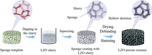
The procedure for the preparation of porous ceramics by the replica method is as follows: first, the polyurethane foam is pre-treated by impregnating it in a solution of sodium carboxymethyl cellulose (CMC, [C6H7O2(OH)2OCH2COONa]n, 99.5%, Sinopharm Group) at a concentration of 20 wt% for 10 h and then dried. The purpose of the pre-treatment is to increase the adhesion of the polyurethane foam and allow the ceramic paste to adhere better to the organic template. Then LZO slurry was prepared by mixing deionized water and ethanol in the ratio of 1:1 by volume, adding 10–20 vol% of LZO powder and 0.6 wt.% (based on LZO) dispersant ammonium citrate (AC, C6H17N3O7, analytically pure, Tianjin Fuchen, China), and mixing and ball milling for 24 h to obtain a uniform slurry. The templates are then dipped into the slurry and impregnated under vacuum for 10 min. The impregnated templates are removed, squeezed to remove the excess slurry, and dried at 60°C. After removing the template at 500°C for 2 h, the porous ceramics were sintered at 1500°C for 2 h. The preparation process is shown in .
Figure 1. Preparation of LZO porous ceramics by the replica method.
2.2. Characterisation
The viscosity was measured by a rotary rheometer (MCR302, Anton Paar GmbH, Austria). The contact angle was measured using an optical contact angle measuring instrument (DSA100, Kruss, Germany). Thermal analysis results of porous ceramic bodies were obtained using a differential scanning calorimeter (DSC214, NETZSCH, Germany). The microstructures of the porous ceramics were obtained using a scanning electron microscope (SEM, VEGA3 SBH, Tescan). The overall three-dimensional structure of the porous ceramic samples was observed using Micro-CT (ZEISS Xradia 520, Germany). The pore size was counted using Nano Measure software. The porosity was calculated by using the equation , where
is the density of the porous ceramic sample,
is the theoretical density of compact LZO ceramic, which is 6.05 g/cm3. The compressive strength was measured using a universal testing machine (GNT100, NCS Testing Technology Co., Ltd., China) (sample size of 15 mm × 15 mm × 15 mm). The crosshead speed was 0.5 mm/min. The thermal conductivity at room temperature was measured with a thermal conductivity meter (TC3000E, XIATECH, China). Infrared photos of high-temperature fire resistance tests were taken by an infrared camera (R5009-DNU, Nippon Avionics Co., Ltd., Japan) (sample thickness of 1 cm).
3. Results and discussion
The key step of the replica method is the cladding of the slurry on the template. To achieve a good coating effect, the slurry needs to have good fluidity and a good bond with the template [Citation24]. Slurry with good flow properties tends to have low viscosity, which can be adjusted by the content of dispersant. Ammonium citrate is an ionic dispersant, and its dispersing mechanism is an electrostatic stabilization mechanism, which consists of citrate ions adsorbed on the surface of particles to form a double electric layer and repulsive forces arising from the same charge between particles [Citation25]. shows the shear-viscosity curves of the slurry at different AC contents. The curves for different AC additions all showed shear-thinning characteristics. When the AC content is 0.5 wt%, the citric acid ions are partially adsorbed on the surface of the particles, and there is a certain repulsive force between the particles. When the AC content increases to 0.6 wt%, the viscosity drops to the lowest level, and citrate ions are fully adsorbed on the surface of the particles with the maximum interparticle repulsion. Further increasing the content, the viscosity becomes larger, which is due to the free citrate ions generated by the excess AC compressing the double electric layer and causing the interparticle repulsion. The inter-particle repulsive force decreases. Therefore, optimal dispersant AC content is 0.6 wt%, where the viscosity of the slurry is lowest and the slurry flows well in the template.
Figure 2. (a) The function of viscosity with rotation speed with different dispersant contents; (b) contact angle of slurry with different water to alcohol ratio; (c) shear rate-viscosity curve of slurry with different water to alcohol ratio.
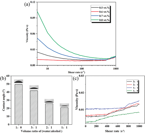
To enhance the cladding properties of the ceramic slurry on the template, the solvent composition was investigated. Deionized water is usually used as the solvent for the slurry in the replica method because additives such as dispersants need to be dissolved in water to work. However, the surface tension of water is high. Ethanol with a lower surface tension is introduced as a solvent mixed with water to enable the coating quality of the slurry on the template skeleton. From , it can be seen that the surface tension of the slurry of water solvent is larger, 49°, and the contact angle of the slurry of alcohol-water-based solvent is obviously reduced. The contact angle keeps decreasing with the increase of the ethanol ratio, and when the alcohol-water based ratio is 1:1, the contact angle decreases to 23°. shows the viscosity shear curves of different alcohol-to-water ratios of the slurry. Four different alcohol-to-water ratios of the slurries are shear thickening phenomena, which are caused by the increase in particle collisions at high-speed shear [Citation26]. At the same time, the viscosity increased slightly with the increase in alcohol ratio, but the viscosity of the slurry was very low with good flowability.
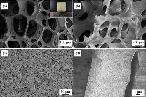
The microstructure of the organic foam template is shown in , where the foam itself has some elasticity and can return to its original shape after extrusion. There is a three-dimensional skeleton structure with interconnected pores, with pores of hundreds of microns. The pore size of the foam template is usually several millimeters for porous ceramics by the replica method, as the large pore size of the template can reduce the requirements for slurry flow and coating properties. The dried samples after slurry impregnation-extrusion are shown in , and it can be seen that the template skeleton is completely covered by ceramic particles, and the ceramic particles are tightly and uniformly distributed. The pores between the skeletons were not blocked by the slurry, and the slurry and the template achieved a good coating.
Figure 3. SEM images of green body by the replica method (sample with coating content of 10.5): (a) polyurethane foam template, (b-d) SEM images of dry green body.
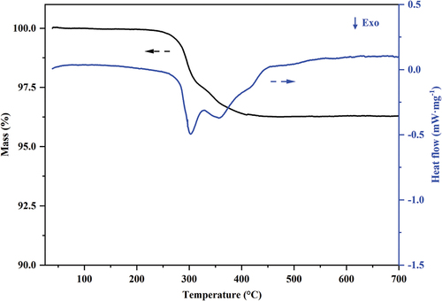
The TG-DSC curve of the dried sample with a coating content of 10.5 is shown in . The TG curve shows a significant mass loss from 250 to 420°C with a weight loss of 4 wt%, which is consistent with the mass ratio of the foam template in the dried sample. Based on the slope of the weight loss section of the TG curve and the corresponding two peaks, it can be judged that the heat absorption peak at 300°C is the thermal decomposition of the polymer into small molecules, and the exothermic peak at 360°C is the further thermal oxidative decomposition of small molecules into carbon dioxide, ammonia gas, etc. After 420°C, the sample mass no longer changes, and the organic foam template has been completely removed.
Figure 4. TG-DSC curve of dry green body (sample with coating content of 10.5).
By adjusting the solid phase content of the slurry from 10 vol% to 20 vol%, it is possible to adjust the coating content on the organic foam template. The SEM of LZO porous ceramics with different slurry loadings is shown in . The pore size of the porous ceramics is reduced compared with that of the foam template, and the skeleton structure of the replica method is formed by the sintering of ceramic particles covered with the template, and some of the pores form “pore walls” due to slurry plugging. The ceramic skeleton becomes progressively thinner as the amount of coating content decreases, and cracks in the ceramic skeleton and collapse of the hollow skeleton when the amount of coating content decreases to 6.4 or less. The “pore wall” formed by the slurry plugging is a curved surface of ceramic particles closely connected to each other.
Figure 5. SEM images of LZO porous ceramics with different coating contents (100×): (a) 13.7, (b) 10.5, (c) 6.4, (d) 4.6, (e) The micro-CT of LZO porous ceramics (sample with coating content of 10.5).
shows the micro-CT image of the sample with a coating content of 10.5. The porous ceramic and the organic foam template show the same skeleton structure, both with interconnected pores and a three-dimensional skeleton structure with a pore size of 100–500 μm. Due to the resolution limitation of the test, the microstructure of the skeleton could not be further observed.
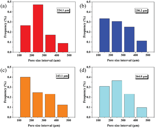
Magnified observation of the skeleton part of LZO porous ceramics with different coating contents shows that the skeleton is hollow, as shown in , which is due to the pore structure of several tens of microns left after the removal of the template at 500°C. The ceramic particles originally covered with the template formed a hollow pore structure after high temperature sintering, resulting in a special secondary pore structure. The skeleton diameter was in the range of 10–40 μm, and the hollow structure was damaged by a partial collapse of the skeleton structure as the amount of coating contents decreased. With a pore size of hundreds of microns between the skeletons as primary pores and the hollow structure of the skeletons forming secondary pores with pore sizes of tens of microns, LZO porous ceramics prepared by the replica method exhibit a hierarchically porous structure. The pore size distribution of LZO porous ceramics with different coating contents is shown in . Pore sizes of LZO porous ceramics ranged from 100 to 500 μm, and the average pore size increased from 224.1 μm to 264.0 μm as the coating content decreased from 13.7 to 4.6. The decrease in ceramic coating content led to fewer ceramic particles covering the template and increasing the pore size.
Figure 6. SEM images of skeleton structure of LZO porous ceramics with different coating contents (1000×): (a) 13.7, (b) 10.5, (c) 6.4, (d) 4.6.
Figure 7. Pore size distribution of LZO porous ceramics with different coating contents: (a) 13.7, (b) 10.5, (c) 6.4, (d) 4.6.
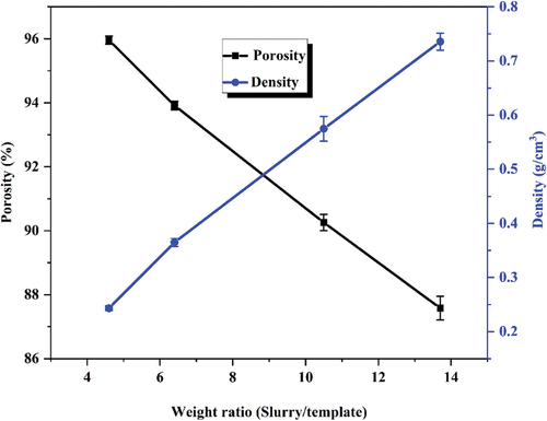
The porosity and density of LZO porous ceramics with different coating contents were measured, and the results are shown in . The porosity of porous ceramics prepared by the replica method is high. Since the foam template itself has very high porosity, the porosity of the green body is also very high after the ceramic slurry has coated and dried on the template, and the porosity is further increased after the template is removed to obtain a hollow skeleton, resulting in a porosity of 87.6%-96.0%. At the same time, the porosity and density of LZO porous ceramics can be adjusted by changing the coating content. The porosity increased from 87.6% to 96.0%, and the corresponding density decreased from 0.736 g/cm3 to 0.242 g/cm3 when the coating content was reduced from 13.7 to 4.6.
Figure 8. Density and porosity of LZO porous ceramics with different coating contents.
The compressive strength and the room temperature thermal conductivity of LZO porous ceramics with different coating contents are shown in , with coating contents ranging from 4.6 to 13.7 and compressive strengths of 0.13–0.74 MPa. The low compressive strength of porous ceramics is due to the fact that its hollow pore structure adversely affects the strength of the skeleton, and the hollow structure of the skeleton collapses as the coating content decreases, further reducing its mechanical properties. Rigid insulation tiles are typical insulation materials used in hypersonic vehicles. They are made of high-temperature resistant ceramic fibers prepared into a porous structure under the action of a high-temperature resistant adhesive. The parameters of fiber insulation tile materials that have been widely used are as follows: density 0.1–0.5 g/cm3, room temperature thermal conductivity ≥ 0.05 W/(m·K), and compressive strength 0.2–1.8 MPa [Citation27–30]. Although the compressive strength of the porous ceramics prepared in this study is low, it is still in the strength range interval of widely used rigid insulation tiles. Therefore the mechanical properties are satisfactory for use.
Figure 9. Compressive strength and thermal conductivity at room temperature of LZO porous ceramics with different coating contents.
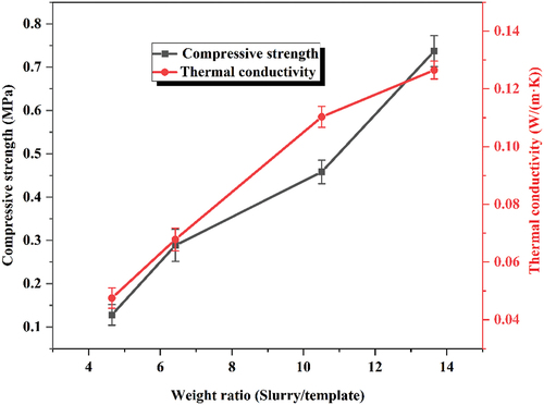
High porosity and open pores are characteristics of LZO porous ceramics made by the replica method. Firstly, the large amount of air phase can effectively reduce the thermal conductivity, and secondly, the distribution of interconnected air phases in the open pore structure increases the thermal resistance of heat transfer in the ceramic phase to a certain extent, so the room temperature thermal conductivity of porous ceramics is low. The thermal conductivity of porous ceramics gradually increased from 0.048 W/(m·K) to 0.126 W/(m·K) as the coating content increased from 4.6 to 13.7. The porosity decreases significantly when the coating content increases, and the thermal conductivity gradually increases because the porous ceramics prepared by this method have a larger pore size of 100–500 μm, so the increased ceramic phases are connected to a greater extent, and it is easy to form a continuous heat transfer path.
illustrates the thermal conductivity and porosity of various typical porous ceramics for thermal insulation [Citation22,Citation24,Citation31–47]. The porous ceramic located in the lower right corner has excellent thermal insulation properties. The figure shows that the porosity of most porous insulation ceramics is between 65–85%, and the thermal conductivity is 0.05–0.65 W/(m·K) at this porosity. Compared with other porous ceramic materials and LZO porous ceramics prepared by other methods, the porous LZO ceramics prepared by the replica method in this experiment have higher porosity and lower thermal conductivity.
Figure 10. Thermal conductivity and porosity of various typical porous ceramics.

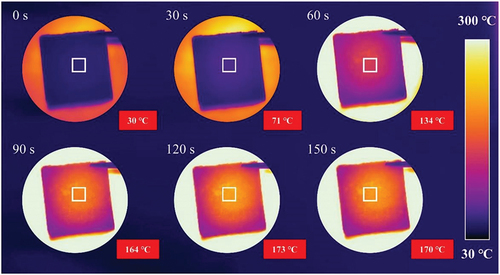
The high-temperature thermal insulation of LZO porous ceramics was tested by heating with a butane torch, and the temperature of the cold side of the sample is shown in . When the hot-side temperature was about 1200°C, the temperature of the cold-side gradually increased with the increase in heating time after the beginning of heating, and the temperature distribution of the cold-side decreased in all directions with the flame heating point as the center. The maximum temperature of the cold side reached 71°C at 30 s. When the heating time exceeded 120 s, the temperature on the cold side gradually stabilized. The temperature on the cold side stabilized gradually, reaching 170°C. The temperature difference between the cold side and the hot side of the sample was over 1000°C.
Figure 11. Cold-side temperature of LZO porous ceramics (sample with coating content of 4.6, 1 cm thickness).
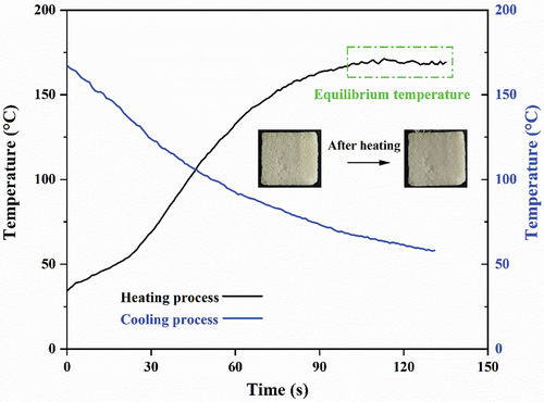
The temperature change curve of the porous ceramic cold side during the heating process and the cooling process is shown in . During the heating process, the temperature of the cold side rose slowly with the heating time, and the temperature stabilization platform appeared at about 100 s with a temperature of about 170°C. At this time, the heat absorbed and emitted by the porous ceramic cold side reached a dynamic equilibrium. The cooling process also decreased slowly, finally reaching 60°C in about 130 s. The heating and cooling processes are relatively similar in time, and the cooling process did not slow down significantly in the low-temperature section below 100°C, which was due to the fact that the pore structure was a few hundred microns in size and has a large heat transfer coefficient with the surrounding air, resulting in faster heat dissipation. The appearance and shape of the samples did not change significantly before and after heating, as shown in the inset photos.
Figure 12. Cold-side temperature of LZO porous ceramics during the heating and cooling process.
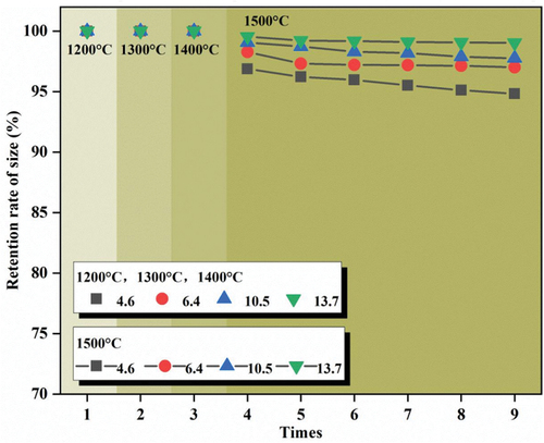
The radial linear shrinkage of LZO porous ceramics after heat treatment at different temperatures is shown in . When the heat treatment temperature was below 1500°C, no sintering shrinkage occurred in the samples with different coating content after heat treatment, which proved the good high-temperature stability of lanthanum zirconate material. When the heat treatment temperature was increased to 1500°C, the samples produced sintering shrinkage after heat treatment, and the size retention rate was 96.9% after one heat treatment for the sample with a coating content of 4.6. The size reduction of the samples with different coating content produced different degrees of size reduction, and the size retention rate became larger as the sample coating content increased. This is due to the fact that samples with high coating contents have a relatively dense ceramic grain arrangement, which means that there are relatively fewer pores in the pore wall, and thus less sintering power.
Figure 13. Size retention rate of LZO porous ceramics after heat treatment.
4. Conclusions
LZO porous ceramics were prepared by the replica method. When the optimized dispersant content in the slurry was 0.6 wt% with an alcohol-to-water ratio of 1:1, this led to good coating quality of the ceramic slurry on the sponge template. LZO porous ceramics with porosity 87.6%-96.0%, pore size 100–500 μm, and an open pore structure were prepared. The pore structure showed the same three-dimensional skeletal structure as the template, and the pores were interconnected with each other. The samples had skeletal structures with different hollow degrees, forming a hierarchically arranged pore structure. The room-temperature thermal conductivity of the porous ceramics was 0.048–0.126 W/(m·K), while the compressive strength was 0.13–0.74 MPa. LZO porous ceramics with a coating content of 4.6 had a high porosity of 96.0% and a thermal conductivity of 0.048 W/(m·K) at room temperature. A high-temperature insulation performance test shows that the temperature difference between the cold side and the hot side of the sample is about 1000°C. No sintering shrinkage occurred in the samples at heat treatment temperatures below 1500°C, which proved the good high-temperature stability of LZO porous ceramics. LZO porous ceramic prepared by the replica method is a promising material for high-temperature insulation applications.
Acknowledgments
We would like to acknowledge the Analytical & Testing Center of Northwestern Polytechnical University for the XRD, SEM, and other analyses.
Disclosure statement
No potential conflict of interest was reported by the author(s).
Additional information
Funding
References
- Ohji T, Fukushima M. Macro-porous ceramics: processing and properties. Int Mater Rev. 2012;57(2):115–131. doi: 10.1179/1743280411Y.0000000006
- Huo WL, Zhang XY, Chen Y, et al. Mechanical strength of highly porous ceramic foams with thin and lamellate cell wall from particle-stabilized foams. Ceram Int. 2018;44(5):5780–5784. doi: 10.1016/j.ceramint.2017.11.202
- Chen Y, Wang N, Ola O, et al. Porous ceramics: light in weight but heavy in energy and environment technologies. Mat Sci Eng R. 2021;143:100589. doi: 10.1016/j.mser.2020.100589
- Studart AR, Gonzenbach UT, Tervoort E, et al. Processing routes to macroporous ceramics: a review. J Am Ceram Soc. 2006;89(6):1771–1789. doi: 10.1111/j.1551-2916.2006.01044.x
- Huo CB, Tian XY, Nan Y, et al. Hierarchically porous alumina ceramic catalyst carrier prepared by powder bed fusion. J Eur Ceram Soc. (2022);40(12):4253–4264. doi: 10.1016/j.jeurceramsoc.2020.03.059
- Colombo P, Bernardo E. Macro- and micro-cellular porous ceramics from preceramic polymers. Compos Sci Technol. (2003);63(16):2353–2359. doi: 10.1016/S0266-3538(03)00268-9
- Huang J, Yao WX. High-temperature mechanical properties of strain isolation pad for thermal protection system. J Spacecraft Rockets. (2018);55(4), 848–855. doi: 10.2514/1.A34093
- Minas C, Carnelli D, Tervoort E, et al. 3D printing of emulsions and foams into hierarchical porous ceramics. Adv Mater. 2016;28(45):9993–9999. doi: 10.1002/adma.201603390
- Yang JF, Zhang GJ, Ohji T. Fabrication of Low-Shrinkage, Porous Silicon Nitride Ceramics by Addition of a Small Amount of Carbon. J Am Ceram Soc, 2011;84, 639–641. doi:10.1111/j.1151-2916.2001.tb00890.x.
- Fukasawa T, Ando M, Ohji T, et al., Synthesis of Porous Ceramics with complex pore structure by freeze-dry processing. J Am Ceram Soc. (2001);84(1):230–232. doi: 10.1111/j.1151-2916.2001.tb00638.x
- Han Y, Zhou LJ, Liang YX, et al. Fabrication and properties of silica/mullite porous ceramic by foam-gelcasting process using silicon kerf waste as raw material. Mater Chem Phys. 2020;240:122248. doi: 10.1016/j.matchemphys.2019.122248
- Nor MAAM, Hong LC, Ahmad ZA, et al. Preparation and characterization of ceramic foam produced via polymeric foam replication method. J Mater Process Technol, 2008; 207(1–3): 235–239. doi: 10.1016/j.jmatprotec.2007.12.099
- Gonzenbach UT, Studart AR, Tervoort E, et al. Macroporous ceramics from particle-stabilized wet foams. J Am Ceram Soc, 2007;90(1):16–22. doi: 10.1111/j.1551-2916.2006.01328.x
- Schwartzwalder AVS, Method of making porous ceramic articles, US Patent 3,090,094 (May 21, 1963).
- Lannge FF, Miller K, Open-cell, low-density ceramics fabricated from reticulated polymer substrates. Adv Ceram Mater, 1987; 2(4):827–831. doi: 10.1111/j.1551-2916.1987.tb00156.x
- Brown DD, Green DJ, Am J. Investigation of Strut crack formation in open cell alumina Ceramics. J Am Ceram Soc, 1944; 77(6):1467–1472. doi: 10.1111/j.1151-2916.1994.tb09744.x
- Brezny R, Green DJ, Am J. Fracture behavior of Open-Cell Ceramics. J Am Ceram Soc, 1989;72(7):1145–1152. doi: 10.1111/j.1151-2916.1989.tb09698.x
- Ashby MF, Medalist RFM, The mechanical properties of cellular solids. Metall Mater Trans A, 1983; 14(9):1755–1769 doi: 10.1007/BF02645546
- Rastogi VK, Jiang B, Sturzenegger PN, et al. A processing route for dip-coating and characterization of multi-structured ceramic foam. Ceram Int. 2019;45(17):21887–21893. doi: 10.1016/j.ceramint.2019.07.199
- Chen F, Yang Y, Shen Q, et al. Macro/Micro structure dependence of mechanical strength of low temperature sintered silicon carbide ceramic foams. Ceram Int. 2012;38(6):5223–5229. doi: 10.1016/j.ceramint.2012.03.030
- Liu DB, Shi BL, Geng LY, et al. High-entropy rare-earth zirconate ceramics with low thermal conductivity for advanced thermal-barrier coatings. J Adv Ceram, (2022) 11(6):961–973 doi: 10.1007/s40145-022-0589-z
- Meng XY, Xu J, Zhu JT, et al. Hierarchically porous lanthanum zirconate foams with low thermal conductivity from particle-stabilized foams. J Am Ceram Soc, 2020; 103(11): 6088–6095. doi: 10.1111/jace.17341
- Meng XY, Xu J, Zhu JT, et al., J Eur Ceram Soc, 41, 6010–6017 (2021). Enhancing the thermal insulating properties of lanthanum zirconate porous ceramics via pore structure tailoring (12). doi: 10.1016/j.jeurceramsoc.2021.05.032
- Liang X, Li YW, Liu J, et al. Fabrication of SiC reticulated porous ceramics with multi-layered struts for porous media combustion. Ceram Int. 2016;42(11):13091–13097. doi: 10.1016/j.ceramint.2016.05.093
- Appiagyei KA, Messing GL, Dumm JQ. Aqueous slip casting of transparent yttrium aluminum garnet (YAG) ceramics. Ceram Int. 2008;34(5):1309–1313. doi: 10.1016/j.ceramint.2007.03.010
- Tseng WJ, Li SY, Rheology of colloidal BaTiO3 suspension with ammonium polyacrylate as a dispersant. Mater Sci Eng A, (2002);333(1–2):314–319. doi: 10.1016/S0921-5093(01)01856-1
- Cooper PA, Hollyway PF, The shuttle tile story. Astro Aero, (1981);19:24–36 doi:10.2514/3.60100.
- Frosch RA, Leiser DB, Goldstein HE, Fibrous refractory composite insulation. US Patent 4,148,962 (1979 April 10).
- Dichiara RA, Method of making a permeable ceramic tile insulation. US Patent 6,613,255 (2002 Oct 17).
- Guo LL, Tao X, Guo AR, et al. Coatings on rigid ceramic insulations:evolution and surface properties. Mater Rep, (2016);30:119–126. doi:10.11896/j.issn.1005-023X.2016.19.017.
- Yang FY, Chen GB, Zhao S, et al. Preparation of high-strength porous mullite ceramics and the effect of hollow sphere particle size on microstructure and properties. Ceram Int, (2022); 48(13):19367–19374. doi: 10.1016/j.ceramint.2022.03.231
- Yang Z, Yang FY, Zhao S, et al., In-situ growth of mullite whiskers and their effect on the microstructure and properties of porous mullite ceramics with an open/closed pore structure. J Eur Ceram Soc, (2021);41(16):299–308. doi: 10.1016/j.jeurceramsoc.2021.09.045
- Gong LL, Wang YH, Cheng XD, et al. Thermal conductivity of highly porous mullite materials. Int J Heat Mass Transf. 2013;67:253–9. doi: 10.1016/j.ijheatmasstransfer.2013.08.008
- Choo TF, Salleh MAM, Kok KY, et al., Modified cenospheres as non-sacrificial pore-forming agent for porous mullite ceramics. Ceram Int, (2019);45(17), 21827–21834. doi: 10.1016/j.ceramint.2019.07.189
- Bucevac D, Maletaskic J, Omerasevic M, Porous acicular mullite ceramics fabricated with in situ formed soot oxidation catalyst obtained from waste MoSi2. Ceram Int, (2017). 43(13): 9815–9822 doi: 10.1016/j.ceramint.2017.04.161
- Hu LF, Wang CA, Huang Y. Porous yttria-stabilized zirconia ceramics with ultra-low thermal conductivity. J Mater Sci. 2010;45(12):3242–3246. doi: 10.1007/s10853-010-4331-9
- Li XX, Yan LW, Zhang YB, et al., Lightweight porous silica ceramics with ultra-low thermal conductivity and enhanced compressive strength. Ceram Int, (2022;48(7): 9788–9796 doi: 10.1016/j.ceramint.2021.12.180
- Ren YH, Zhang B, Ye J, et al. Preparation of porous Y2SiO5 ceramics with high porosity and extremely low thermal conductivity for radome applications. Ceram Int. 2023;49(2):2394–2400. doi: 10.1016/j.ceramint.2022.09.212
- Wu Z, Sun LC, Wang JY. Synthesis and characterization of porous Y 2 SiO 5 with low linear shrinkage, high porosity and high strength. Ceram Int. 2016;42(13):14894–14902. doi: 10.1016/j.ceramint.2016.06.128
- Wu Z, Sun LC, Wan P, et al. Preparation, microstructure and high temperature performances of porous γ-Y2Si2O7 by in situ foam-gelcasting using gelatin. Ceram Int. 2015;41(10):14230–14238. doi: 10.1016/j.ceramint.2015.07.051
- Meng XY, Xu J, Yang RW, et al., Lanthanum zirconate porous ceramics with controllable secondary pores for high-temperature thermal insulation. Ceram Int, 2022;48(22):33976–33983 doi: 10.1016/j.ceramint.2022.07.347
- Lang Y, Dong YH, Zhou J, et al. YSZ fiber-reinforced porous YSZ ceramics with lowered thermal conductivity: influence of the sintering temperature. Mater Sci Eng A. 2014;600:76–81. doi: 10.1016/j.msea.2014.02.005
- Liu JJ, Lin YB, Li YW, et al., Effects of pore structure on thermal conductivity and strength of alumina porous ceramics using carbon black as pore-forming agent. Ceram Int, 2016;42(7):8221–8228 doi: 10.1016/j.ceramint.2016.02.032
- Lo YW, Wei WCJ, Hsueh CH. Low thermal conductivity of porous Al2O3 foams for SOFC insulation. Mater Chem Phys. 2011;129(1–2):326–330. doi: 10.1016/j.matchemphys.2011.04.023
- Huang Y, Hu NY, Ye YC, et al. Preparation and pore-forming mechanism of MgO–Al2O3–CaO-based porous ceramics using phosphorus tailings. Ceram Int. 2022;48(20):29882–29891. doi: 10.1016/j.ceramint.2022.06.253
- Rajpoot S, Malik RMYW, Kim Y-W. Low thermal conductivity in porous SiC–SiO2–Al2O3–TiO2 ceramics induced by multiphase thermal resistance. Ceram Int. 2021;47(14):20161–20168. doi: 10.1016/j.ceramint.2021.04.022
- Luo X, Zhang Q, Ye F, et al. Microstructure, mechanical, wave-transparent and heat insulation properties of Si3N4 foam ceramic by organic foam impregnation combined with CVI. J Mater Res Technol, 2023;23: 1332–1346 doi: 10.1016/j.jmrt.2023.01.072