
Abstract
Dc microgrids (MG) have drawn more attention due to the demand for renewable energy sources, energy storage devices in distributed generation, and the separation of DC loads requiring more power converters. This system needed protection DC circuit breakers (DCCB) that could quickly isolate the faults in the system. These devices must be as small and light as possible but should only produce low power loss during the ON state. The impedance source DC circuit breaker was introduced as an improved structure (SSCB) which provided automatic turns off without needing external command due to its natural commutation operation principle. In addition, it had many advantages such as faster response, simpler control design, restricted fault current magnitude, which makes the system more fault-resilient, the fault current will not affect the source or the SCR, coordination of cascaded breakers is automatic, and convenience for protection with power converters. This paper presents different impedance source DC circuit breakers such as ZCB, ΓCB, TCB, and YCB. It will show their benefits and drawbacks, which could be used as a helping guide while choosing which type of impedance source DC circuit breakers is suitable for a specific application.
General Statement
The Impedance source circuit breakers are developed from the solid-state DC circuit breakers. They had been preferred over the traditional types of DCCB in protection systems because of their various advantages, such as the fastest response that could isolate the fault in microseconds, automatically isolated without needing external control or sensing elements, and so forth. This paper is the first review paper on the different kinds of Impedance source circuit breakers. It also presents different impedance source DC circuit breakers such as ZCB, ΓCB, TCB, and YCB. Moreover, showing their benefits and drawbacks. So, it provided a helping guide when choosing an impedance source DC circuit breaker suitable for a specific application or as a reference guide for additional research or topological enhancements.
Reviewing Editor:
1. Introduction
During the last few years, DC microgrids (MG) have been using renewable energy sources (solar cells, fuel cells) and energy storage devices (batteries and supercapacitors) in distributed generation. Also, due to the separation of DC loads (electric vehicles (EV), light-emitting diode bulbs, water heaters, and domestic DC-powered appliances), more power converters are required if ac microgrids are used, which leads to an increment in energy loss. There are several benefits can be shown if DC microgrids are used, such as higher system efficiency, lower cost, smaller system size, high reliability, no problem with synchronization, safer, and more simple and feasible power regulation (Justo et al., Citation2013; Kim et al., Citation2018; Keshavarzi et al., Citation2017; Kumar et al., Citation2017; Sharma & Sood, Citation2022).
Even though the DC microgrids have a significant benefit, there is an essential issue since the DC lacks a natural zero-crossing point. This makes it difficult to withstand the fault current because of the arc that appears, which might cause damage to power electronic components (Kim et al., Citation2018; Li et al., Citation2019). This could be solved by adding an arc extinguishing device, injecting a current of the opposite polarity, or inserting a counteracting voltage. These techniques were used in mechanical DC circuit breakers (MCB). The primary advantages of MCBs are minimal power loss (the contacts are of lower resistance) and inexpensive cost; nevertheless, the main downsides are sluggish reaction time, low durability, and limited current interruption capabilities (Bucher & Franck, Citation2016; Lumen et al., Citation2020).
To overcome the drawbacks of (MCCB), a faster solid-state DC circuit breaker (SSCB) is proposed instead of (MCCB), which provide a long lifetime and higher reliability. The disadvantages of this CB were the higher resistance of semiconductor switches of SSCB, lack of galvanic separation, and the demand for the construction of an additional forced commutation branch and sensing circuit, which increases the circuit’s expense and complexity (Bhatta et al., Citation2021; Bhatta, Citation2021; Kim et al., Citation2018; Li et al., Citation2019; Lumen et al., Citation2020; Raghavendra et al., Citation2022; Qi et al., Citation2017). A hybrid DC circuit breaker (HCB) is an improvement to a traditional (MCB); it constructed by connecting solid-state DC switches (IGBT) and a fast mechanical switch to provide a lower power consumption, better galvanic isolation, and higher stability than (SSCB) and quicker fault interruption over MCB. However, the disadvantage of complexity in operation, more costly, and low response speed have still existed (Keshavarzi et al., Citation2017; Mackey et al., Citation2017; Raghavendra et al., Citation2022).
An impedance-source DC circuit breaker (ISCB) is an improved structure to (SSCB) which provided automatic turns-off without needing to external command due to its natural commutation operation principle (Chang et al., Citation2016; Lumen et al., Citation2020). Also, it had the advantages of a faster response that could isolate the fault in microseconds, a simpler in control design that doesn’t need an extra-circuit for fault sensing because fault detection can be achieved by only checking whether the SCR is off, or the current value dropped below excepted value (Corzine & Ashton, Citation2012). The following sections will be discussed different ISCBs topologies with some advantages and drawbacks of theses topologies.
2. Z-source DC circuit breaker
2.1. Unidirectional Z-source DC breaker
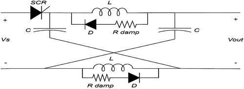
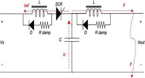
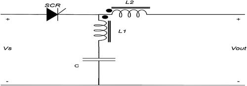
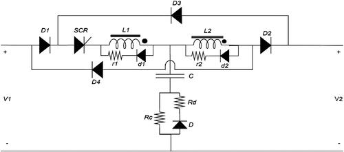
The idea of z-source was first proposed as inverter topology using an impedance source network. It consists of two inductors and capacitors in a cross shape to couple the DC power source with the output converter or with a load which enables the circuit to run in both buck and boost state and provides electromagnetic interference protection. The boost is caused by the z-source, which permits the inverter to enter another state, and it can short-circuit its DC bus. This functionality was used later to handle faults in DC power systems. Due to the inductors inside the z-source network, there wasn’t a direct short circuit to the capacitor voltages during a fault that happens in this system (Peng, Citation2003). In addition, it was recommended to use this configuration with other types of power converters, which led to the development of various new “z-source network” topologies, as illustrated in (Hasan Babayi Nozadian et al., Citation2019). This recommendation has been carried out in (Corzine & Ashton, Citation2012); the z-source concept has been used to protect DC systems from faults by developing a “Cross ZCB”, as shown in . The benefits of this design included quick, automatic interruptions without needing an external command, no reflected current, low conduction losses, and low cost. The reverse current provided by the shunt capacitor makes the SCR turn off automatically so that the fault current will not be reflected on the SCR or the power source, resulting in lower conduction loss and cost compared with (SSCB). However, there were drawbacks, including no common ground between source and load, no sensitivity to lower magnitude fault current, high spark current during reconnection, and not being able to provide long time protection. therefore, an additional control strategy must be used to ensure that the SCR remains unconnected (Li et al., Citation2019; Lumen et al., Citation2020).
Figure 1. Cross ZCB (Corzine & Ashton, Citation2012).
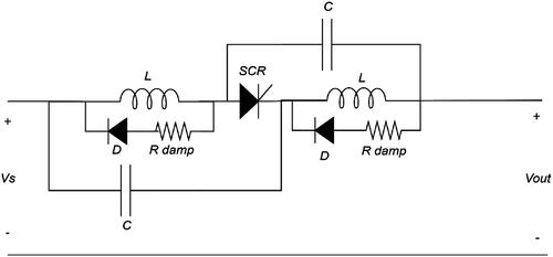
As a solution for no common ground, a “Parallel ZCB” was proposed in (Corzine & Ashton, Citation2011), as shown in . During a fault, SCR had turned off automatically due to the fault current’s natural commutation, which passed in the reverse direction to the steady-state current through the two capacitors then to SCR. Because the return path has no impedance like the inductor in the cross-circuit breaker, this structure has the disadvantages of a high fault current that could be reflected into the source side, high starting current flowing in SCR, and large in size (Corzine & Ashton, Citation2011).
Figure 2. Parallel ZCB (Corzine & Ashton, Citation2011).
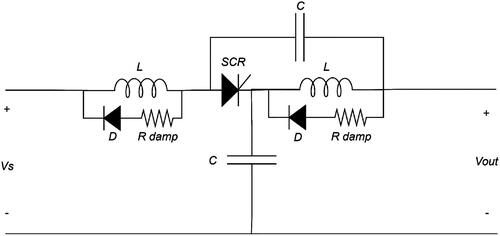
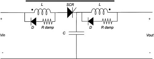
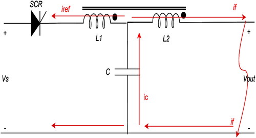
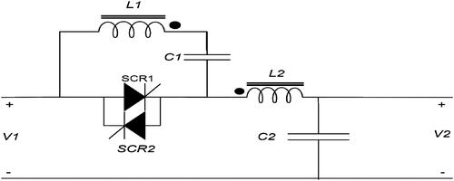
A “Series ZCB” is presented as a development of the conventional types of ZCB, as shown in . The parallel capacitor connection is modified by butting it between the SCR and the ground, creating a common ground between the power source and load. The other benefits of this configuration are significantly lowering the fault current and integrating a low-pass filter (Chang et al., Citation2016; Chang et al., Citation2013).
Figure 3. Series ZCB (Chang et al., 2016; Chang et al., Citation2013).
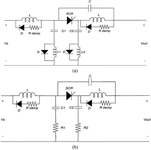
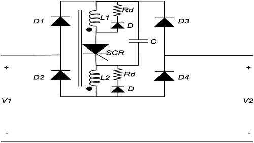
Two modified ZCB topologies were proposed. A capacitor current is reduced by using another capacitive branch on the other side of SCR to divide the current between the two branches during a fault occurs or varies in load value. These two branches allowed the SCR to remain on even when a load was changing in steps. Also, the change in capacitor current will be helpful for fault detection. In the first configuration, each of the two capacitors was connected in series with resistance to limit the value of current passing through the capacitors. In contrast, in the second configuration, inductors were added to do the same, as shown in (Overstreet et al., Citation2014).
Figure 4. (a) and (b) Two modified ZCB (Overstreet et al., Citation2014).
In (Maqsood & Corzine, Citation2015b), the coupled inductors were used in the design of ZCB to reduce the weight of inductors, which is about 30% of the previous size, as shown in . In addition, the inductor volume could be decreased to a rough 25% due to coupling inductors that can be coiled on the same core. Moreover, the coupling is involved in the commutation procedure and gives a path for a reflecting current. The ZCB can act with just one capacitor rather than two, which reduces the essential parts of the ZCB.
Figure 5. ZCB with coupled inductors (Maqsood & Corzine, Citation2015b).
Instead of using the two inductors in fault isolation, the proposed configuration includes a transformer that can switch off the SCR using the current induced inside the two windings, as shown in . The transformer’s two coils had no physical connection and could only interact through induction, and the LC branches were removed. The source current drops to zero after the SCR is turned off. It also provides a solution to the problem of highly reflected current to the source, so the transformer’s turn ratio may be modified to modify the load variation’s critical value (Li et al., Citation2019).
Figure 6. ZCB with transformer (Li et al., Citation2019).
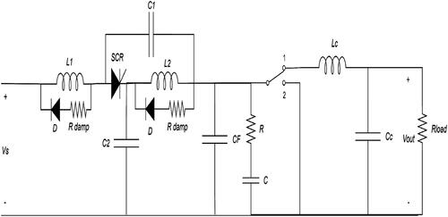
A modified design was done to the series ZCB by making it convenient for loads with power electronic converters, as shown in . The fundamental issue with such loads was because of the discontinuous load current, which might lead to a discharge in the capacitor of the ZCB. It makes the SCR current zero, resulting in an unwanted commutate of SCR during the steady-state situation. It must be maintained the current flowing through the SCR higher than its holding current to avoid the undesired commutation of the SCR. A passive input filter could be added between the breaker ZCB and the converter to ensure continuous current through the SCR. The used filter added a new problem because it contains an inductor, which increased the electric system’s size. To solve such a problem, it is proposed to use the two inductors of ZCB in filtering instead of adding an external inductor. However, this led to an increase in the current ripple, which might cause tripping of the ZCB because of the load changing. This is solved by adding a small value resistance in series with the ZCB capacitor to reduce the ripple current in SCR (Surwade et al., Citation2020).
Figure 7. Modified series ZCB convenient for loads with power electronic converters (Surwade et al., Citation2020).
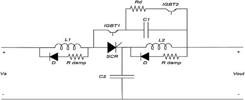
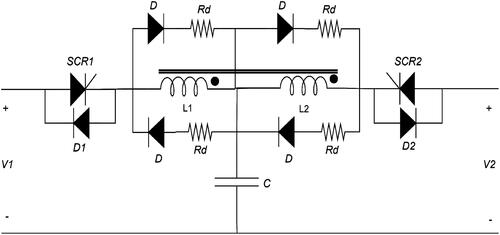
Although the better features of series ZCB and its modified type, it is still had disadvantages, such as the negative current circulates in the load when ZCB reclosing and commissioning, there is undesirable power flow throughout the load under commissioning, and the flowing of high starting current in the SCR when ZCB is reclosing and commission. To solve these problems, a modified series ZCB is presented in (Raghavendra et al., Citation2022), as shown in , in which two power electronics semiconductor devices, such as IGBTs, were employed to regulate the charging and discharging characteristics of the capacitor C1. These IGBTs work in a mutually complementary manner.
Figure 8. Modified series ZCB with enhanced performance during commissioning and reclosing (Raghavendra et al., Citation2022).
2.2 Bi-direction Z-source DC breaker
Unidirectional circuit breakers are the better choice in applications with one source and one load. At the same time, the current directions in large power systems can be changed based on load distribution. Additionally, some components inside the system both transmit and receive energy from the grid. So, the breakers must be bi-directional in these situations.
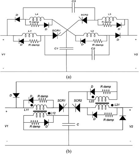
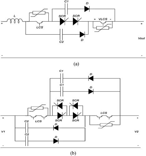
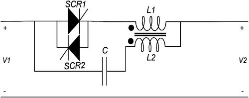
Two “Bi-direction cross ZCB” configurations were proposed as the first bi-direction impedance source DC circuit breaker configurations, as shown in . Both configurations are constructed by the restructure of two cross ZCBs to create bi-directional current flow flexibility. The direction of the current flow is directed by the control gate signals for SCR (Maqsood & Corzine, Citation2014).
Figure 9. (a) and (b) are two configurations of bidirectional cross ZCB (Maqsood & Corzine, Citation2014).
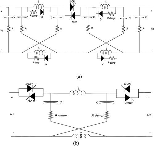
The first configuration, in , had been the preferred selection because it contained only one SCR in each direction of power fellow, reducing the power losses to 50% compared to the second configuration. The other advantage was that when several such breakers were linked in series, including such an LC circuit on the two sides of SCR terminals would create considerable latency in fault current growth. This latency is beneficial in locating the fault position. Both designs did not treat the load’s transient current as a fault current. Also, this design offers considerably better isolation since the input current drops to zero instantaneously, with no transient problem.
In (Maqsood & Corzine, Citation2015a), a modification to both the uni-directional breakers in (Corzine & Ashton, Citation2012) and the bi-directional breakers in (Maqsood & Corzine, Citation2014) was done to enable them to reclose after being open in a few microseconds. This ability is used in the coordination control of ZCB. The two modified bidirectional cross ZCB with reclosing ability. As shown in .
Figure 10. (a) Modified unidirectional and (b) Modified bidirectional ZCB with reclosing ability (Maqsood & Corzine, Citation2015a).
and configurations had many disadvantages, such as the existence of back-to-back thyristors used in each configuration to transfer power in two directions. Furthermore, they need to use one or more inductances inside the negative polarity line, resulting in a common ground loss. The back-to-back thyristors also require numerous separate drivers, increasing the cost of the ZCB.
The disadvantages above have led to the developing of a “bidirectional fault current limiter and interrupter” (FCLI), as shown in . It can control the direction of power flow and limit and interrupt fault current alongside its primary task of circuit breaking. The disadvantages of this configuration were a complex driver circuit and a high reflecting current to the source. However, it has the advantages of reliable and simple construction, minimum conductivity power loss, softly tripped load current, and no inductor in the return path, so that (FCLI) had a common ground (Keshavarzi et al., Citation2017).
Figure 11. ZCB with bidirectional fault current limiter and interrupter (FCLI) (Keshavarzi et al., Citation2017).
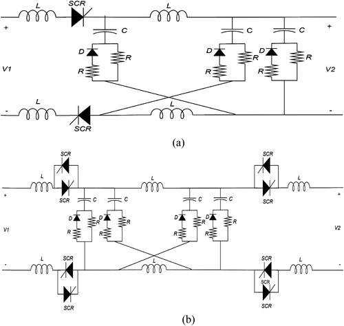
Both the unidirectional coupled-inductor and the bidirectional coupled-inductor DC breakers were presented. The two proposed architectures used the SCR to isolate the fault current immediately, as shown in . These breakers had a control switch built-in, allowing them to be manually controlled without causing too much disturbance to the system. Also, central control was suggested to control multi-breakers’ operations in the DC microgrid. Moreover, the other advantage of this bidirectional DC breaker was the symmetric fault-current-level structure, the common ground, and no reflected current to the source presented with these two breakers (Maqsood & Corzine, Citation2016).
Figure 12. (a) Unidirectional coupled-inductor ZCB. (b): Bidirectional coupled-inductor ZCB (Maqsood & Corzine, Citation2016).
These configurations of bi-directional ZCB (Bi-ZCB) and bidirectional ZCB with a coupled inductor (Bi-CZCB), as shown in , may remove the fault in any path of power flow. They use the SCR as an isolating switch to isolate the source from the fault current. Also, there is no need for fault detection or sensing elements. In the second configuration, coupled inductance is employed for SCR commutation. Coupled inductors assist in minimizing inductor cost and size and eliminate the requirement for an extra capacitor in the configuration. Throughout the (Bi-CZCB) configuration, the fault current was reflected at the power supply side, but the source current instantly fell to zero. Also, common ground is provided by the two configurations (Savaliya et al., Citation2016).
Figure 13. (a) Bi-directional ZCB (b) Bi-directional ZCB with coupled inductor (Savaliya et al., Citation2016).
Although the previous advantage, these two configurations still had a problem with the complexity of the circuit topologies due to the existence of many components in the circuit configuration, making it costly and increasing its volume.
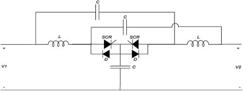
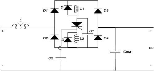
The series ZCB circuit breaker architecture allows for bidirectional power transfer was proposed as shown in . The existence of a diode bridge allows current to flow in a bi-direction with only a single SCR switch. No extra passive components were needed when compared to the unidirectional series ZCB. It includes the benefits of the unidirectional series ZCB, such as the common ground, convenience for input filtering of a power converter, and no input current spike due to reverse recovery of the thyristor. The problem of the reflected fault current to the source still exists (Ryan et al., Citation2018).
Figure 14. A bidirectional series ZCB (Ryan et al., Citation2018).
The proposed circuit in was presented as an improved bidirectional solid-state circuit breaker with the coupled inductor of three windings architecture. It solves the problem of a lack of common ground between the load and the power source. And it also had the advantage of simpler construction and fewer components compared with the former bidirectional DC circuit breakers, which had more complicated circuit construction (Wang et al., Citation2019).
Figure 15. Bidirectional solid-state circuit breaker for DC microgrid (Wang et al., Citation2019).
In (Savaliya & Fernandes, Citation2018; Savaliya & Fernandes, Citation2021) presented a bidirectional ZCB with a coupled inductor (Bi-CZCB) with reclosing and re-breaking abilities, as shown in . This compact structure breaker was constructed with a single coupled inductor instead of two separate coupled inductors, as mentioned in (Bi-CZCB). To accomplish its performance in bi-directional power flow situations, this means reducing the number of components. It had other advantages, such as the fault being isolated within a few microseconds, it also had common ground, being able to work with loads with step changes for the current more than twice its steady-state value, and it had a smaller size and cost. Although these advantages, this breaker had some drawbacks such as it contained 4 SCR switches which needed a complex control circuit, and also there were two switches in each case of power flow which led to an increase in power conduction loss, also in microgrid applications the transformation ratio was commonly recommended to be a unity one to keep the same fault current threshold which was preferred by input and output ports. As a result, adjusting the transformer ratio to repair the malfunction problem would be inconvenient for such a breaker. So, a three-winding transformer could solve this problem, as shown in other types of breakers.
Figure 16. Modified bi-directional ZSB with a coupled inductor (Bi-CZCB) (Savaliya & Fernandes, Citation2018; Savaliya & Fernandes, Citation2021).
The previous replacement of the costly traditional SSCB was based on using an IGBT switch (or any fully-controlled switch) by new SSCB designs based on an SCR switch. However, because the SCR is a half-controlled device, it cannot be switched off actively. So, a combination of IGBT (or any fully-controlled switch) and SCR was proposed in (Shu et al., Citation2020), as shown in . This configuration was known as an active ZCB (AZCB). The suggested AZCB has the following advantages: active and bidirectional current isolation capacity, simple and compact topology, economic architecture, and lower power conduction losses.
Figure 17. (a) Unidirectional (AZCB). (b) bidirectional (AZCB) (Shu et al., Citation2020).
A coupled-inductor-based bidirectional ZCB (CI-BZCB) structure was introduced, as shown in . It can detect and isolate the fault in the DC power system. The suggested configuration used fewer components than previous configurations, and the coupled inductors minimized the breaker’s size (Marwaha et al., Citation2020).
Figure 18. A coupled-inductor-based bidirectional ZCB (CI-BZCB) (Marwaha et al., Citation2020).
presented another coupled-inductor-based bidirectional ZCB. It uses a diode bridge to provide bidirectional energy flow. The SCR is switched off by the effect of the mutual of the coupled inductor. The innovative bidirectional circuit breaker includes fewer components, a common ground, no reflected current, and the ability to stay on even when the load changes in steps (Wang et al., Citation2021).
Figure 19. A coupled-inductor-based bidirectional ZCB (Wang et al., Citation2021).
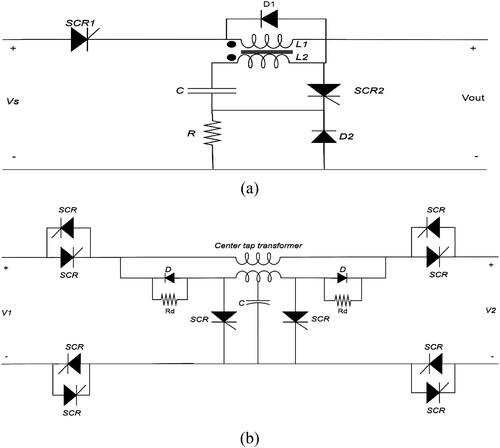
The bidirectional ZCB with fault decision-making ability is presented in . It was capable of responding to a fault within a few microseconds. Varying the turn ratio of a coupled inductor makes it easy to adjust the fault threshold value. Except for component selection, both voltage and current values had lower effects on other features of the proposed architecture. The suggested topology in the core section employs only a single coupled inductor with a central tapped structure, which improves the coupled inductor’s utilization ratio and decreases the volume, number of components, and cost of the breaker when compared to past DC circuit breakers, which were a significant improvement (Yang et al., Citation2021).
Figure 20. Bidirectional ZCB with fault decision-making ability (Yang et al., Citation2021).
The primary issue in conventual ZCBs was that they couldn’t handle bidirectional energy flow, which means they couldn’t satisfy the charging or discharging requirements of a fuel cell in an electric car system. As a result, bidirectional ZCBs were created to accommodate bidirectional power flow. However, these breakers resulted in various additional challenges, including a complicated construction, many components needed, and the lack of common ground between the fuel cell and the load. In (Zhang et al., Citation2020), a new ZCB architecture was proposed, which could be used in a fuel cell system. As shown in , the breaker structure depended on the parallel ZCB, and it also employs a diode rectifier with a bridge structure and transformer windings. This structure greatly simplified the circuit breaker’s configuration and eliminated difficulties like false triggering due to the step load and many components. This new circuit breaker offers better performance than the existing bidirectional circuit breakers.
Figure 21. Bidirectional ZCB for fuel cell related system (Zhang et al., Citation2020).
For DC microgrid protection, a bidirectional coupled ZCB with a specific O-shaped impedance network denoted as OZCB, was suggested, as shown in . This breaker maintains the advantages of automatic fault isolation, lowered reflected fault current, bidirectional operation capability, symmetric fault-current-level structure, the existence of common ground, and fewer components than existing bidirectional ZSCBs. Furthermore, because each conduction path in the breaker had only a single semiconductor device and a single coil of a transformer, the OZCB had a higher power efficiency (Zhou et al., Citation2021).
Figure 22. Bidirectional O-ZCB for DC microgrid protection (Zhou et al., Citation2021).
3. Gamma-Z-source DC circuit breaker (Γ-ZCB)
The idea of Γ-ZCB came from the modification of the two inductors of the ZCB with coupled inductor (Maqsood & Corzine, Citation2015b). They presented to consist of a capacitor connected in series with the secondary winding of the coupled inductors, which led to the production of gamma (Γ) shape ZCB (Corzine, Citation2015), as shown in . This new configuration employs a short conduction channel between the breaker and the mutual coupling inductors to turn off the SCR automatically and quickly in reaction to the fault. The principle of operation was that under normal operating conditions. The load current has a fixed value as it travels inside the path of the SCR. While in the event of a fault or a variation in load current, the secondary winding of the inductor had been fed from the instantaneous current of the capacitor. This variable inductor current causes an opposite current to flow through the primary coil to the SCR. The opposing current could cause the SCR to turn off automatically once it drops to zero or less. Let’s suppose that all the variable flux developed in the secondary coil reaches the primary inductor; the magnitude of the primary current differs from the size of the capacitor current. This differentiation is determined by the transformation ratio, N1/N2 (Al-Khafaf & Asumadu, Citation2017).
Figure 23. (a) Circuit breakers for DC microgrids (b) A variation to the circuit breakers (Corzine, Citation2015).
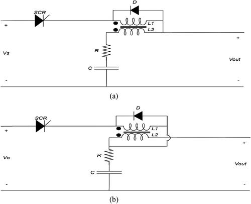
A variation to the proposed circuit was also presented, as shown in . Both the primary and secondary windings carry the main path of current. The fault current travels into the secondary winding, causing the SCR current to reduce to zero. It must be noticed that the turn ratio N1/N2 could be adjusted such that a substantial variation in load would not be detected as a fault by the breaker. This breaker had other advantages, such as it has common ground between source and load and no reflecting current to the source; it also has the essential feature of having a low-pass filtering action and reliable operation, as seen from its transfer function (Yang et al., Citation2021).
The effect of the coupling coefficient of coupled inductors in Γ-ZCB was found to interrupt fault current. The coupling coefficient must be greater than a void value, but it does not have to be a perfect unity. Changing the coupled inductor turn ratio could also vary the void value of the coupling coefficient. The desired coupling coefficient decreases as the turn ratio rises, giving more freedom to choose the coupling degree. The structure of the breaker is seen in (Al-Khafaf & Asumadu, Citation2017).
Figure 24. Γ-ZCB (Al-Khafaf & Asumadu, Citation2017).
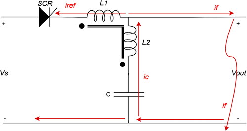
The specific circuit breaker’s model is typically a high-order circuit that is difficult to solve. The absence of a simpler topology and parameter design that takes parameters such as (line inductance, line resistance, and load capacitance) into account limits their practical technical uses. As a result, a reduced topology of the circuit breaker was provided, as shown in , which depended on the equivalent mathematical model (Diao et al., Citation2021).
Figure 25. Modified Γ-ZCB (Diao et al., 2021).
4. T-source DC circuit breaker
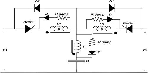
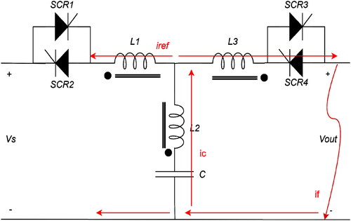
Some ZCB designs have disadvantages and limitations, such as common ground, incorrect load step response, fault ring current in the source, and input harmonic resonance. The T-source circuit breaker (TCB) was presented to overcome these disadvantages, as shown in . By rearranging the two coils of the Γ-source breaker using a coupled transformer of two windings and a capacitor, both were built in a T-shape impedance network (Li et al., Citation2016).
Figure 26. T-source circuit breaker (TCB) (Li et al., Citation2016).
Under normal conditions, standard current flows from source to load over SCR and transformer; in fault conditions, the fault current passes from the capacitor through L2. The primary windings carry a reverse current Ir, induced by the coupling transient fault current in the secondary windings. If Ir reaches the normal current level, the SCR is turned off by forcing commutations.
The suggested circuit may turn off automatically under transient fault events. Opposing previous solid-state breakers, the transformer’s turn ratio controls the TCB's current gain; this is a unique feature not seen in previous breakers. Also, this breaker could distinguish between a short-circuit fault and a step-change in load.
This circuit breaker also had other advantages, such as a low-pass filter acting in its transfer function of input voltage, common ground, no reflect current to source during a fault, and rapid response of breaker.
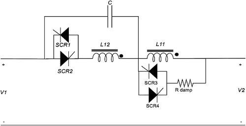
A bidirectional (TCB) series circuit was presented, as shown in . During short-circuit faults, the suggested topology uses a T-source transformer to naturally commutate off the SCR through coupling and reducing the SCR current to zero, preventing circuit breaking under high current operating conditions. Moreover, this structure allows a bidirectional response to faults on both the source and load side using a single controlled switch, without additional passive components, as opposed to the unidirectional series TCB topology. Also, during the steady state, the bidirectional TCB can be equal to a low-pass filter in its input without adding extra adverse effects to the system (Song et al., Citation2019).
Figure 27. Bidirectional (TCB) series circuit (Song et al., Citation2019).
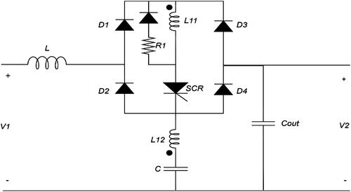
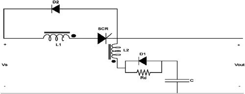
A modified T-source circuit breaker was presented, as shown in , which consists of the following components: SCR, two diodes, coupled inductor, and a variable resistor. This breaker decreases the connected inductor’s excitation current biased by over 40%, which lowers the possibility of magnetic saturation. This TCB also has a soft starting circuit that limits the overcurrent during the turning on of the breaker (Diao et al., Citation2021).
Figure 28. A modified T-source circuit breaker for flexible DC distribution networks (Diao et al., 2021).
An improvement to the previously suggested TCBs has been made to present TCB with bidirectional operation capability, as shown in , which can be used in MVDC systems that need bidirectional power flow between distinct sources and loads. The design employs a coupled-inductor, seven diodes, and a capacitor to protect T-source breakers against short-circuit and overload conditions in forward and backward flow while keeping the same current flow direction in TCB. This breaker also supplied the system with low-pass filter properties (Sapkota et al., Citation2020).
Figure 29. Modified T-source circuit breaker for bidirectional operation in MVDC (Sapkota et al., Citation2020).
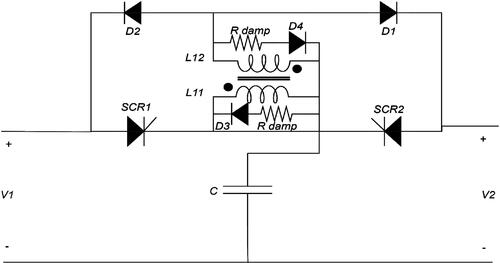
Classical bidirectional ZCBs and TCBs, contain several power semiconductor components in a steady-state path, lowering the circuit breaker efficiency. As a result, it presented a new bidirectional TCB with just a single SCR in the steady-state line, as shown in . The suggested circuit breaker on-state power loss can be reduced by more than 50% compared to traditional bidirectional ZCBs and TCBs (Song et al., Citation2021).
Figure 30. Bidirectional T-source circuit breaker for low voltage DC distribution network (Song et al., Citation2021).
5. Y-source DC circuit breaker
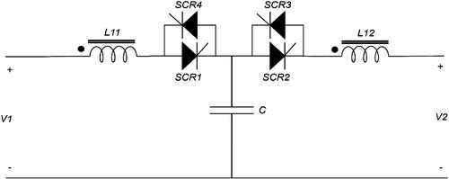
Both (Al-Khafaf & Asumadu, Citation2018; Al-Khafaf & Asumadu, Citation2021; Al-Khafaf & Asumadu, Citation2018) presented a Y-source impedance circuit breaker (YCB), as shown in , that contained three magnetically coupled inductors and a single capacitor. The self and mutual inductance levels determine this architecture’s symmetric input and output impedance. DC electrical power can flow in two directions through the T1, T3, or T2, T4. The YCB can be employed on the branches that have to change their current direction during fault events. The power flow direction is decided by which pair of SCR switches are on. It was also found that the coupling coefficient (K) directly impacts the fault conductance’s lowest value and slope rate. The YCB should be set to a coupling level greater than zero. The turn ratio also controls this value. The important feature of this breaker is the higher gain of reverse current provided by the two secondary windings; the gain value depends on the turn ratio of the three windings. Also, the breaker can work with a step load change without interrupting. Although the advantages of YCB, some parameters still need enhancement, such as lowering the leakage inductance, winding loss, and the magnetizing current.
Figure 31. Y-source impedance circuit breaker (YCB) (Al-Khafaf & Asumadu, Citation2018; Al-Khafaf & Asumadu, Citation2018).
6. Comparative summary
The advantages and disadvantages of different impedance source DC circuit breaker configurations are summarized in . This table can help choose an impedance source DC circuit breaker for a specific application or help researchers with additional research or topological enhancements.
Table 1. A comparative review of various impedance source circuit breaker configurations.
7. Conclusion
This paper reviewed and compared the main features of different impedance source DC circuit breakers, such as ZCB, Γ-CB, TCB, and YCB. Each structure has certain advantages and disadvantages according to the circuit breaker size, cost, complexity, number of components, control system, speed of response, etc. The comparison shows that the circuit breakers with coupled inductors had been preferred over the non-coupled inductors circuit breakers according to their various advantages. Also, the circuit breakers with symmetrical input and output impedance are most preferred. Finally, the circuit breaker with three coupled inductors, such as YCB, was preferred because its distinctive characteristic is that both of its secondary windings work together to provide a large reflected current that forces SCRs to commutate, the faster response time for such DC circuit breakers. The comparison presented in this paper can be used as a helping guide when choosing an impedance source DC circuit breaker suitable for a specific application or as a reference guide for additional research or topological enhancements.
Disclosure statement
No potential conflict of interest was reported by the author(s).
References
- Al-Khafaf, H., & Asumadu, J. (2017). Γ-Z-source DC circuit breaker operation with variable coupling coefficient k. 2017 IEEE International Conference on Electro Information Technology (EIT). IEEE. https://doi.org/10.1109/EIT.2017.8053411
- Al-Khafaf, H., & Asumadu, J. (2018). Bi-directional Y-source DC circuit breaker design and analysis under different conditions of coupling. 2018 9th IEEE International Symposium on Power Electronics for Distributed Generation Systems (PEDG). IEEE. https://doi.org/10.1109/PEDG.2018.8447539
- Al-Khafaf, H., & Asumadu, J. (2018). Y-source bi-directional dc circuit breaker. 2018 International Power Electronics Conference (IPEC-Niigata 2018-ECCE Asia). IEEE. https://doi.org/10.23919/IPECNiigata2018-ECCE40317.2018.9309129
- Al-Khafaf, H., & Asumadu, J. (2021). Efficient protection scheme based on Y-source circuit breaker in bi-directional zones for MVDC micro-grids. Inventions, 6(1), 18. https://doi.org/10.3390/inventions6010018
- Bhatta, S. (2021). Specification, control, and applications of Z-source circuit breakers for the protection of DC power networks [PhD dissertion]. Electrical & Computer Engineering, Old Dominion University.
- Bhatta, S., Fu, R., & Zhang, Y. (2021). A new design of Z-source capacitors to ensure SCR's turn-off for the practical applications of ZCBs in realistic DC network protection. IEEE Transactions on Power Electronics, 36(9), 10089–10096. https://doi.org/10.1109/TPEL.2021.3063021
- Bucher, M. K., & Franck, C. M. (2016). Fault current interruption in multiterminal HVDC networks. IEEE Transactions on Power Delivery, 31(1), 87–95. https://doi.org/10.1109/TPWRD.2015.2448761
- Chang, A. H., Avestruz, A. T., Leeb, S. B., & Kirtley, J. L. (2013). Design of dc system protection. 2013 IEEE Electric Ship Technologies Symposium (ESTS). IEEE.
- Chang, A. H., Sennett, B. R., Avestruz, A.-T., Leeb, S. B., & Kirtley, J. L. (2016). Analysis and design of DC system protection using Z-source circuit breaker. IEEE Transactions on Power Electronics, 31(2), 1036–1049. https://doi.org/10.1109/TPEL.2015.2415775
- Corzine, K. A. (2015). Circuit breaker for DC micro grids. 2015 IEEE First International Conference on DC Microgrids (ICDCM). IEEE. https://doi.org/10.1109/ICDCM.2015.7152042
- Corzine, K. A., & Ashton, R. W. (2011). Structure and analysis of the Z-source MVDC breaker. 2011 IEEE Electric Ship Technologies Symposium. IEEE.
- Corzine, K. A., & Ashton, R. W. (2012). A new Z-source DC circuit breaker. IEEE Transactions on Power Electronics, 27(6), 2796–2804. https://doi.org/10.1109/TPEL.2011.2178125
- Diao, X., Liu, F., Song, Y., Xu, M., Zhuang, Y., & Zha, X. (2021). Topology Simplification and Parameter Design of Z/T/C-Source Circuit Breakers. IEEE Journal of Emerging and Selected Topics in Power Electronics, 9(6), 7066–7077. https://doi.org/10.1109/JESTPE.2021.3054435
- Diao, X., Liu, F., Song, Y., Xu, M., Zhuang, Y., & Zha, X. (2021). An integral fault location algorithm based on a modified T-source circuit breaker for flexible DC distribution networks. IEEE Transactions on Power Delivery, 36(5), 2861–2871. https://doi.org/10.1109/TPWRD.2020.3028423
- Hasan Babayi Nozadian, M., Babaei, E., Hosseini, S. H., & Shokati Asl, E. (2019). Switched Z‐source networks: a review. IET Power Electronics, 12(7), 1616–1633. https://doi.org/10.1049/iet-pel.2018.5436
- Justo, J. J., Mwasilu, F., Lee, J., & Jung, J.-W. (2013). AC-microgrids versus DC-microgrids with distributed energy resources: A review. Renewable and Sustainable Energy Reviews, 24, 387–405. https://doi.org/10.1016/j.rser.2013.03.067
- Keshavarzi, D., Ghanbari, T., & Farjah, E. (2017). A Z-source-based bidirectional DC circuit breaker with fault current limitation and interruption capabilities. IEEE Transactions on Power Electronics, 32(9), 6813–6822. https://doi.org/10.1109/TPEL.2016.2624147
- Kim, K., Park, K., Roh, G., & Chun, K. (2018). DC-grid system for ships: a study of benefits and technical considerations. Journal of International Maritime Safety, Environmental Affairs, and Shipping, 2(1), 1–12. https://doi.org/10.1080/25725084.2018.1490239
- Kumar, D., Zare, F., & Ghosh, A. (2017). DC microgrid technology: system architectures, AC grid interfaces, grounding schemes, power quality, communication networks, applications, and standardizations. IEEE Access. 5, 12230–12256. https://doi.org/10.1109/ACCESS.2017.2705914
- Li, C., et al. (2016 A novel solid-state protection scheme for DC system [Paper presentation]. in 2016 IEEE 8th International Power Electronics and Motion Control Conference (IPEMC-ECCE Asia),. IEEE.
- Li, W., Wang, Y., Wu, X., & Zhang, X. (2019). A novel solid-state circuit breaker for on-board DC microgrid system. IEEE Transactions on Industrial Electronics, 66(7), 5715–5723. https://doi.org/10.1109/TIE.2018.2854559
- Lumen, S. S., Kannan, R., & Yahaya, N. Z. (2020). DC circuit breaker: A comprehensive review of solid-state topologies. 2020 IEEE International Conference on Power and Energy (PECon). IEEE.
- Mackey, L., Rachi, M. R. K., Peng, C., & Husain, I. (2017). Z-source circuit breaker utilizing ultra-fast mechanical switch for high efficiency dc circuit protection. 2017 IEEE Second International Conference on DC Microgrids (ICDCM). IEEE. https://doi.org/10.1109/ICDCM.2017.8001084
- Maqsood, A., & Corzine, K. (2014). The Z-source breaker for fault protection in ship power systems. 2014 International Symposium on Power Electronics, Electrical Drives, Automation and Motion. IEEE.
- Maqsood, A., & Corzine, K. (2015b). Z-source Dc circuit breakers with coupled inductors. 2015 IEEE Energy Conversion Congress and Exposition (ECCE). IEEE. https://doi.org/10.1109/ECCE.2015.7309928
- Maqsood, A., & Corzine, K. (2016). DC microgrid protection: Using the coupled-inductor solid-state circuit breaker. IEEE Electrification Magazine, 4(2), 58–64. https://doi.org/10.1109/MELE.2016.2544240
- Maqsood, A., & Corzine, K. A. (2015a). The Z-source breaker for ship power system protection. 2015 IEEE Electric Ship Technologies Symposium (ESTS). IEEE. https://doi.org/10.1109/ESTS.2015.7157907
- Marwaha, M., Satpathi, K., Pou, J., Molligoda, D. A., Gajanayake, C., & Gupta, A. K. (2020). Coupled-inductor-based bidirectional Z-source breaker for DC system protection. IECON 2020 the 46th Annual Conference of the IEEE Industrial Electronics Society. IEEE.
- Overstreet, A., Maqsood, A., & Corzine, K. (2014). Modified z-source dc circuit breaker topologies. 2014 Clemson University Power Systems Conference. IEEE.
- Peng, F. Z. (2003). Z-source inverter. IEEE Transactions on Industry Applications, 39(2), 504–510.
- Qi, L. L., Antoniazzi, A., Raciti, L., & Leoni, D. (2017). Design of solid-state circuit breaker-based protection for DC shipboard power systems. IEEE Journal of Emerging and Selected Topics in Power Electronics, 5(1), 260–268. https://doi.org/10.1109/JESTPE.2016.2633223
- Raghavendra, V., Banavath, S. N., & Thamballa, S. (2022). Modified z-source dc circuit breaker with enhanced performance during commissioning and reclosing. IEEE Transactions on Power Electronics, 37(1), 910–919. https://doi.org/10.1109/TPEL.2021.3092773
- Ryan, D. J., Torresan, H. D., & Bahrani, B. (2018). A bidirectional series Z-source circuit breaker. IEEE Transactions on Power Electronics, 33(9), 7609–7621. https://doi.org/10.1109/TPEL.2017.2764903
- Sapkota, S., Pokharel, K., Wang, Y., Li, W., & Wang, H. (2020). Modified T-source circuit breaker for bidirectional operation in MVDC. 2020 IEEE Sustainable Power and Energy Conference (iSPEC). IEEE. https://doi.org/10.1109/iSPEC50848.2020.9351283
- Savaliya, S. G., & Fernandes, B. G. (2018). Modified bi-directional Z-source breaker with reclosing and rebreaking capabilities. 2018 IEEE Applied Power Electronics Conference and Exposition (APEC). IEEE. https://doi.org/10.1109/APEC.2018.8341608
- Savaliya, S. G., & Fernandes, B. G. (2021). Performance evaluation of a modified bidirectional Z-source breaker. IEEE Transactions on Industrial Electronics, 68(8), 7137–7145. https://doi.org/10.1109/TIE.2020.3000133
- Savaliya, S., Singh, S., & Fernandes, B. G. (2016). Protection of DC system using bi-directional Z-Source Circuit breaker. IECON 2016-42nd Annual Conference of the IEEE Industrial Electronics Society. IEEE.
- Sharma, S., & Sood, Y. R. (2022). Microgrids: A review of status, technologies, software tools, and issues in Indian power market. IETE Technical Review, 39(2), 411–432. https://doi.org/10.1080/02564602.2020.1850367
- Shu, J., Wang, S., Ma, J., Liu, T., & He, Z. (2020). An active Z-source DC circuit breaker combined with SCR and IGBT. IEEE Transactions on Power Electronics, 35(10), 10003–10007. https://doi.org/10.1109/TPEL.2020.2980543
- Song, W., An, N., & Wang, Y. (2019). A novel bidirectional t-source dc circuit breaker for dc microgrids. 2019 14th IEEE Conference on Industrial Electronics and Applications (ICIEA). IEEE. https://doi.org/10.1109/ICIEA.2019.8833694
- Song, Y., Yu, Y., Wang, S., Liu, Q., & Li, X. (2021). A novel efficient bidirectional T-source circuit breaker for low voltage DC distribution network. 2021 IEEE 12th International Symposium on Power Electronics for Distributed Generation Systems (PEDG). IEEE. https://doi.org/10.1109/PEDG51384.2021.9494238
- Surwade, V., Savaliya, S., & Pimple, B. (2020). A modified Z-source DC circuit breaker for power electronic converter load application. 2020 IEEE International Conference on Power Electronics, Drives and Energy Systems (PEDES). IEEE. https://doi.org/10.1109/PEDES49360.2020.9379331
- Wang, Y., Dong, R., Xu, Z., Kang, Z., Yao, W., & Li, W. (2021). A Coupled-Inductor-Based Bidirectional Circuit Breaker for DC Microgrid. IEEE Journal of Emerging and Selected Topics in Power Electronics, 9(3), 2489–2499. https://doi.org/10.1109/JESTPE.2020.3016647
- Wang, Y., Li, W., Wu, X., & Wu, X. (2019). A novel bidirectional solid-state circuit breaker for DC microgrid. IEEE Transactions on Industrial Electronics, 66(7), 5707–5714. https://doi.org/10.1109/TIE.2018.2878191
- Yang, Y., Huang, C., Zhao, Z., Xu, Q., & Jiang, Y. (2021). A new bidirectional DC circuit breaker with fault decision-making capability for DC microgrid. IEEE Journal of Emerging and Selected Topics in Power Electronics, 9(3), 2476–2488. https://doi.org/10.1109/JESTPE.2020.3023653
- Zhang, B., Wang, Y., Fei, Y., Li, Y., Song, J., Wang, H., Lin, Q., & Li, W. (2020). A novel bidirectional Z-source DC circuit breaker for fuel cell related system. IECON 2020 the 46th Annual Conference of the IEEE Industrial Electronics Society. IEEE.
- Zhou, Z., Jiang, J., Ye, S., Yang, D., & Jiang, J. (2021). Novel bidirectional O-Z-source circuit breaker for DC microgrid protection. IEEE Transactions on Power Electronics, 36(2), 1602–1613. https://doi.org/10.1109/TPEL.2020.3006889