
 ?Mathematical formulae have been encoded as MathML and are displayed in this HTML version using MathJax in order to improve their display. Uncheck the box to turn MathJax off. This feature requires Javascript. Click on a formula to zoom.
Abstract
This paper revisits a classical problem in linkage mechanism design, specifically the design of centric crank-rocker mechanisms for a specified rocker stroke with unit time ratio. Beyond the traditional objective of minimizing the transmission angle’s deviation from 90 degrees, this paper uses another objective: maximizing the shortest-to-longest link-length ratio in the linkage. The former objective ensures motion transmission quality in the mechanism, while the latter aims to make the mechanism less sensitive to variations in link lengths. It is shown that these two objectives are inherently conflicting, necessitating a trade-off solution. To address this, a Pareto front is developed by analyzing the governing design equations. The front is further normalized by relating each objective to its limit value. A design example using the normalized front is provided that showcases different optimization options. The TOPSIS method is used to illustrate the selection of a preferred design alternative.
REVIEWING EDITOR:
1. Introduction
The four-bar mechanism is one of the most widely used mechanisms in various engineering applications. One of the simplest applications of this mechanism is converting the continuous rotation of the input link into a re-rocking motion of the output link, in which case the mechanism is called a crank-rocker. The mechanism can be either centric or non-centric. In a centric mechanism, the forward and return strokes of the rocker take equal times, while in a non-centric one the return stroke is made faster than the forward (working) stroke. The non-centric mechanisms are commonly called quick-return mechanisms. The crank-rocker mechanism has been widely studied by researchers aiming to improve its design from various perspectives.
The task of designing a mechanism in general is to specify appropriate link lengths that satisfy prescribed motion specifications. In addition to meeting the motion specifications, the design usually is required to satisfy certain desired performance requirements or objectives. One of the performance objectives that is traditionally targeted by mechanism designers is to ensure the highest possible motion transmission quality in the linkage. In the case of a crank-rocker mechanism, motion transmission quality is considered satisfactory if the so-called transmission angle (the included angle between the coupler link and output link) does not deviate strongly from 90 degrees during the motion cycle (Waldron et al., Citation2016; Balli & Chand, Citation2002). Another design objective that designers often seek to achieve is to have a well-proportioned linkage, - one in which the links are of comparable lengths (Waldron et al., Citation2016). This objective is often included in order to reduce the sensitivity of the designed mechanism to variations in its link lengths. It is known that variations of link lengths, which are inevitably caused by manufacturing errors, joint clearances, or link deformations, can lead to large positioning errors and, if one of the links is too small compared with one or more of the other links, the positioning errors become more difficult to control (Fogarasy & Smith, Citation1998; Rothenhofer et al., Citation2010). To avoid this occurrence, mechanism designers usually impose inequality constraints on the minimum and maximum lengths of individual links or, alternatively, limit the smallest link-length ratio in the mechanism to an acceptable minimum (Waldron et al., Citation2016; Norton, Citation2013).
In the literature, the design of crank-rocker mechanisms has been the subject of extensive research over several decades. Research publications consider various design performance requirements. Both analytical and optimization search solutions can be found. Al-Dwairi et al. (Citation2009) proposed an analytical solution for synthesizing crank-rocker and double-crank mechanisms with minimized maximum link-length ratios. The analytical method used led to a single solution suggesting that a mechanism with a minimized largest link-length ratio has coupler link and output link of the same length. The correspondence between crank-rocker and double-crank mechanisms as kinematic inversions was used to develop unified design equations applicable to either mechanism type.
Funabashi and Freudenstein (Citation1979) developed criteria for designing high-speed crank-rocker mechanisms with controlled transmission-angle variation and minimum to maximum link length ratio. The authors derived a family of crank-rocker linkages with an approximately sinusoidal acceleration pattern, nearly simulating the acceleration function of a scotch yoke mechanism. A numerical example was provided illustrating the analytical procedure followed.
Lun and Leu (Citation1996) proposed an analytical procedure to enhance the transmission angle of crank-rocker mechanism over working stroke. The authors presented formulas and charts that facilitate the design with specified optimum options and showed that the feasible ranges of the design variables are widened if the transmission angle over the working stroke is taken for the main design objective.
Mutlu (Citation2021) presented closed-form solutions to the synthesis of crank-rocker mechanisms in different design problem statements. Eight design cases were provided, with each case addressing a different set of design inputs. Closed-form design solutions were achieved by pre-specifying the deviations of transmission angle from 90 degrees.
El-Shakery et al. (Citation2020) developed a methodology for optimally synthesizing crank-rocker mechanism for definite transmission angle deviations. The authors provided three case studies, with each case corresponding to a different problem formulation. Design charts were given that help find a mechanism that satisfies stroke and time ratio values with predefined transmission angle deviations.
Santoro (Citation1992) used Pareto optimization method to design a crank-rocker mechanism based on a compromise between motion transmission quality and the maximum acceleration. The author considered the weighting factors as design variables and arrived at a particular solution to a non-dimensional formulation of the design problem.
Ahmadi and Ahmadi (Citation2022) utilized genetic programming to optimize the crank-rocker design for desired output stroke and time ratio while optimizing the transmission angle and satisfying Grashof conditions. The authors derive explicit mathematical formulations for the dimensions of the crank-rocker mechanism. As a result of the optimization procedure, the authors showed that the optimal design for the specified motion task is one in which the coupler link and output rocker are equal in length.
Nariman-Zadeh et al. (Citation2009) used a hybrid genetic algorithm to optimally design a four-bar mechanism for path generation. The optimization procedure was based on trade-offs between the path tracking error and transmission angle deviation from 90 degrees. The authors provide a design example where two four-bar design solutions were found on the Pareto front of the objective functions.
Valencia-Segura et al. (Citation2021) presented a differential evolution (DE) method for the optimum synthesis of a path-generator crank-rocker mechanism. The authors formulated a constrained optimization problem imposing inequality constraints on minimum and maximum lengths of individual links. Five design cases were presented with and without prescribed timing. The authors confirm that success of the optimization search process is significantly influenced by the formulation of the optimization problem.
Singh et al. (Citation2017) synthesized a crank-rocker mechanism for human knee exoskeleton. The authors formulated a constrained-optimization problem minimizing the Euclidean distance between prescribed and generated trajectories. The constraints were aimed at eliminating branch and order defects, and fulfilling Grashof’s condition. The penalty-function method was used to transform the problem to a non-constrained one. It was concluded that the teaching-learning based algorithm (TLBO) was more efficient computationally than other nature-inspired optimization algorithms such as the genetic algorithm (GA) and particle swarm algorithms (PSO).
More relevant literature on mechanism design up to the year 2017 was reviewed in (Lee & Russell, Citation2017), while a review of multi-objective optimization methods can be found in (Gunantara, Citation2018).
The reviewed works indicate that mechanism design methods fall into two main categories: analytical and numerical optimization techniques. Analytical methods are suitable for problems where design objectives can be directly expressed as functions of design variables, provided the number of design requirements does not exceed the number of mechanism parameters. On the other hand, numerical optimization methods are used for over-constrained problems, where the number of requirements and constraints exceeds the available mechanism parameters. Analytical methods are relatively simpler as they often lend themselves to solving a system of equations in the design unknowns, but they lack flexibility in imposing various design requirements. In contrast, numerical optimization techniques allow for the incorporation of numerous design requirements and constraints, although this comes at the cost of increased complexity and application effort.
This paper presents a novel procedure for designing centric crank-rocker mechanisms based on a trade-off between motion transmission quality and the shortest-to-longest link length ratio in the mechanism. The procedure builds a normalized Pareto front that reveals directly the attainment level for each of the objectives as a percentage of its theoretical (unattainable) maximum. By selecting a trade-off point on the normalized front, the computation of the corresponding mechanism dimensions can be found by the developed design equations. Compared to existing works, the approach taken in this paper relies on establishing a direct relationship between the design objectives. Since the obtained relationship does not involve any of the mechanism link-length ratios, it directly represents the Pareto objectives front, eliminating the need for optimization by numerical or evolutionary methods.
The contributions of this paper are as follows. Firstly, it addresses a problem that has not been explored in the literature as a bi-objective problem; existing works have primarily focused on non-centric mechanisms, the design equations of which are not applicable to the centric ones. Secondly, in existing works, the design objective of controlling the smallest link-length ratio of the linkage has been addressed by imposing constraints on the maximum and minimum lengths of individual links. In this study, however, this ratio has been identified analytically as a function of the motion specifications. Finally, this work establishes the limiting values of the design objectives analytically and provides a normalized Pareto front based on these limits.
The paper is organized as follows. Section 2 presents the mechanism kinematic model and derives the basic design equations. Section 3 formulates the design criteria as functions of the design variables and determines the limiting values of the design criteria. Section 4 derives a direct relationship between the design criteria and presents a Pareto front for the optimization problem. Section 5 provides normalized Pareto fronts for various stroke angles. The last section illustrates the use of the normalized front using four different optimization options and applies TOPSIS methodology for selecting a preferred design alternative.
2. Basic design equations
shows a centric crank-rocker mechanism in its limit positions AB1C1D and AB2C2D. The mechanism consists of four links including crank AB, coupler link BC, rocker CD, and ground link AD. As crank AB rotates 180 degrees from AB1 to AB2, rocker CD moves through a total re-rocking stroke angle Δψ.
Figure 1. Crank-rocker limit positions.
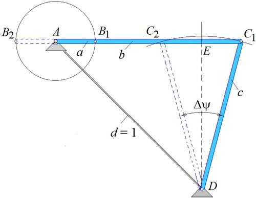
Following the usual practice, we convert to a non-dimensional model of the linkage by taking ground link AD for the unit of length and normalizing the remaining lengths to it. This yields three non-dimensional link-length ratios of the linkage, which are:
(1)
(1)
The design problem hence is to find a suitable design vector x = {a, b, c} to realize the specified stroke angle Δψ for the 180-degree input rotation. Design equations can be developed based on as follows. By noticing that distance C1C2 is equal to B1B2, which in turn equals 2a, and drawing bisector DE normal to C1C2, we write:
(2)
(2)
Bisector DE is common to right triangles EDC1 and EDA, which leads to:
(3)
(3)
EquationEquations (2)(2)
(2) and Equation(3)
(3)
(3) are the basic design equations to be satisfied by the design variables. With three variables in two equations, one free-choice variable is readily available. Most often, mechanism designers employ this freedom solely to improve the motion transmission angle (discussed below). This paper uses a second objective, which is to maximize the shortest-to-longest link-length ratio in the mechanism.
3. Design criteria
3.1. Transmission angle criterion
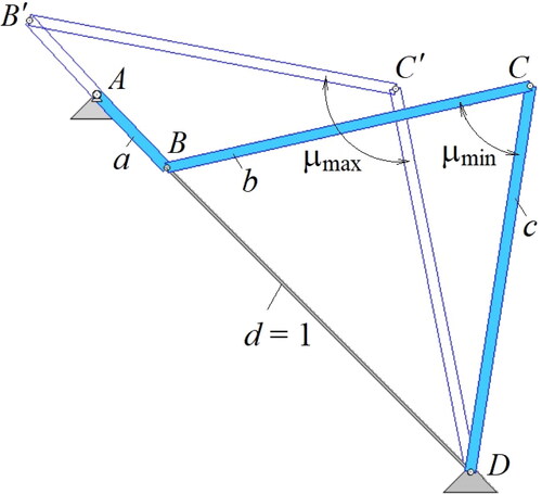
The transmission angle µ in any four-bar mechanism is defined as the included angle between coupler link BC and rocker CD. As the purpose of the mechanism is to transmit torque from link AB to rocker DC, the closer is the transmission angle to 90 degrees, the more efficient is the torque transmission. Over a full cycle of crank AB rotation, the transmission angle varies from some minimum to some maximum, reaching these values in the two positions ABCD and AB′C′D in which input link AB becomes in-line with ground link AD (). Applying the cosine law to triangles BCD and B′C′D of yields:
(4)
(4)
and
(5)
(5)
Figure 2. Positions of extreme transmission angles.
Incorporating EquationEq. (3)(3)
(3) into Equation(4)
(4)
(4) and Equation(5)
(5)
(5) gives:
(6)
(6)
EquationEquation (6)(6)
(6) implies that angles µmin and µmax always deviate equally from 90 degrees and hence have the same meaning from the transmission quality viewpoint. We shall therefore, only consider maximizing µmin in what follows.
3.2. Smallest link-length ratio criterion
To determine which of the link-length ratios of the mechanism is the smallest, we recall that by Grashof’s condition (Waldron et al., Citation2016; Al-Dwairi et al., Citation2009), for a 4-bar mechanism to have at least one link capable of full rotation, its lengths must satisfy the following inequality:
(7)
(7)
where s is the shortest, l is the longest, and p and q are the lengths of the remaining links. Also, by Grashof’s classification, for a 4-bar to perform as a crank-rocker mechanism, the input crank must be the shortest of the links. Thus, considering EquationEq. (7)
(7)
(7) with EquationEq. (3)
(3)
(3) , we conclude that ground link AD must be the longest link and hence, link-length ratio a is the smallest ratio that we seek to maximize in this work. It also follows from EquationEq. (3)
(3)
(3) that
(8)
(8)
Moreover, the following relationship between µmin and Δѱ is obtained by considering EquationEq. (2)(2)
(2) with EquationEqs. (6)
(6)
(6) and Equation(8)
(8)
(8) :
(9)
(9)
EquationEquation (9)(9)
(9) implies that for any specified stroke angle Δѱ, there exists a limiting transmission angle value µlim found at strict equality as:
(10)
(10)
From EquationEq. (10)(10)
(10) , it is seen that the larger the specified Δѱ, the smaller the attainable transmission angle µmin.
4. Solution of the design equations
EquationEquations (2) (3)(3)
(3) , and Equation(6)
(6)
(6) can be solved simultaneously for the link-length ratios, which yields (Al-Dwairi et al., Citation2009):
(11)
(11)
(12)
(12)
(13)
(13)
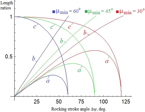
is a plot of EquationEqs. (11)(11)
(11) , Equation(12)
(12)
(12) , and Equation(13)
(13)
(13) as functions of Δѱ for three different values of µmin, for illustration.
It is seen from that for any µmin, ratios a and b approach zero (i.e. the mechanism ceases to exist) when Δѱ approaches its value computed from EquationEq. (10)(10)
(10) .
Figure 3. Link-length ratios vs Δѱ.
5. Pareto front
A Pareto front or Pareto curve in the domain of design criteria in multi-objective optimization problems is an image of all design solutions that are non-dominated to each other (Nariman-Zadeh et al., Citation2009; Jahan et al., Citation2013). Hence, there is not a single solution that would be superior to all other solutions on the front with respect to all design criteria. This in turn means that all design solutions that are on a Pareto front of a given design problem are acceptable solutions, with varying degrees of fulfilling the various design objectives. Consequently, changing the design vector from one point to another would lead to deterioration in at least one of the design objectives. Finding the Pareto front is useful in engineering design problems as it allows the designer to explore the entire objectives space and monitor the design behavior with respect to his/her design decisions.
The Pareto front for the bi-objective problem at hand can be obtained by plotting the link-length ratio a (objective 1) versus the transmission angle µmin (objective 2). This can be achieved by substituting from EquationEqs. (11)(11)
(11) and Equation(12)
(12)
(12) into EquationEq. (13)
(13)
(13) and simplifying, which gives a as a function of µmin and Δѱ as:
(14)
(14)
is a plot of EquationEq. (14)(14)
(14) for different values of the stroke angle Δѱ. It represents the Pareto fronts for those Δѱ values and hence any pair of values (µmin, a) is considered a Pareto-efficient solution.
Figure 4. Pareto fronts for different angles Δѱ.
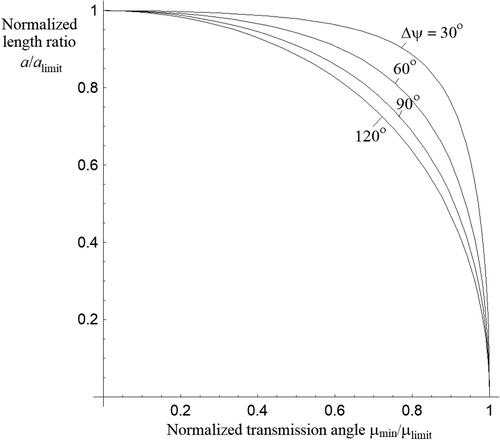
6. Normalizing the Pareto front
The Pareto fronts shown in have the design objectives a and µmin in their absolute scales. As these objectives are of different natures and magnitudes, it would be more insightful to convert to a non-dimensional front. This can be achieved by normalizing each of the design criteria with respect to its limiting value. Here, for any given stroke Δѱ, the limiting value of an objective can be found by setting the other objective to zero.
For the link-length ratio a, substituting µmin = 0 in EquationEq. (14)(14)
(14) gives the limiting value of a as:
(15)
(15)
Similarly, substituting a = 0 in EquationEq. (14)(14)
(14) gives the transmission angle limiting value µlim obtained in EquationEq. (10)
(10)
(10) above.
shows plots of the normalized fronts for different values of the stroke angle Δѱ. The variables on the front’s axes now are the normalized design objectives µmin/µlim and a/alim. It should be noted that if any of the objectives is set to its limiting value, the mechanism ceases to exist. The limiting values therefore are considered unattainable. The next section illustrates how the normalized front can be used to design a mechanism by selecting a desired front point.
Figure 5. Normalized Pareto front for different angles Δѱ.
7. Design example using the normalized front
To illustrate the use of the normalized front to design a crank-rocker mechanism, we here take as an example the case when the required rocker stroke Δѱ is 30 degrees. Below we present four possible optimization options corresponding to four points on the normalized front.
7.1. Optimization by prescribing an objective attainment level
The norms of the design objectives (µmin/µlim and a/alim) used in can be viewed as attainment levels of the objectives. One of the basic optimization methods is when the designer specifies a desired attainment level for one of the objectives based on his/her preference and evaluates the attainment level of the other objective. To illustrate, let the designer decide that a 95%-attainment level for ratio a is desired (i.e. a/alim = 0.95). With Δѱ = 30 degrees, EquationEq. (16)(16)
(16) gives alim = 0.2588 and hence a = 0.95*0.2588 = 0.2459. Substituting this into EquationEq. (14)
(14)
(14) and solving gives µmin = 49.35 degrees. By EquationEq. (10)
(10)
(10) , µlim = 75 degrees and hence the attainment level for µmin is 65.8% (i. e., µmin/µlim = 0.658). This is shown as point P1 in . By EquationEq. (11)
(11)
(11) and EquationEq. (12)
(12)
(12) , the remaining link length ratios are found to be b = 0.3973 and c = 0.9501.
Figure 6. Normalized Pareto front for Δѱ = 30 deg.
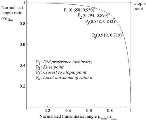
7.2. Knee point based optimization
The knee point of a Pareto front provides a strongly optimum solution (Zhang et al., Citation2015); as shows, any increase in µmin/µlim (the benefit) comes at the expense of a decrease in a/alim (the cost). The knee of the front is a point where µmin/µlim is no longer increasing rapidly, and is no longer worth the decrease in a/alim. Graphically, the knee point is the point of maximum curvature. For the front in , its curvature is found to be maximum at point P2 where µmin/µlim = 0.794 and a/alim = 0.890. Therefore, µmin = 0.794*75 = 59.55 degrees and a = 0.890*0.2588 = 0.2303. Then, by EquationEqs. (11)(11)
(11) and Equation(12)
(12)
(12) , the linkage design based on this point has b = 0.5107 and c = 0.8901.
7.3. Utopia point based optimization
A utopia point in the objectives space is an unattainable point at which both objectives are fully achieved to their maximum possible extents (Lu et al., Citation2011; Han et al., Citation2023). In , the utopia point has coordinates (1, 1) for all fronts. It is generally suggested that the front’s point closest to the utopian provides a strongly Pareto optimum. The shortest distance from the utopian point to the normalized front is found by minimizing the function
(16)
(16)
In , the shortest distance is found to be Lmin = 0.2194 attained at point P3(0.848, 0.842). Since in this example µlim = 75 degrees and alim = 0.2588, we have µmin = 0.848*75 = 63.6 degrees and a = 0.842*0.2588 = 0.2179. Then, by EquationEqs. (11)(11)
(11) and Equation(12)
(12)
(12) , the remaining length ratios are found as b = 0.5821 and c = 0.8418.
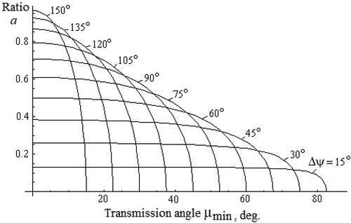
7.4. Optimization by choosing µmin that maximizes the length ratio a
It can be observed from that unlike ratios b and c, length ratio a is not monotonic with respect to Δѱ. For any Δѱ, there exists a unique transmission angle for which ratio a reaches a local maximum, which can be expected to yield a good trade-off and is worth considering. The unique value
can be found based on EquationEq. (14)
(14)
(14) by letting ∂a/∂(Δѱ) = 0. Carrying out the differentiation and simplifying leads to:
(17)
(17)
By accounting for EquationEq. (10)(10)
(10) , EquationEq. (17)
(17)
(17) can be written as:
(18)
(18)
For Δѱ = 30 degrees, in which case µlim = 75 degrees and alim = 0.2588, we find from EquationEq. (18)(18)
(18) that
= 68.9 degrees. This corresponds with point P4(0.919, 0.719) in . Thus, the link-length ratios are a = 0.719*0.2588 = 0.1862 and b = c = 0.7193.
below summarizes the linkage design alternatives resulting from each of the four implemented optimization methods above. shows these alternatives in their minimum-transmission angle positions. The alternatives are drawn to scale with the same fixed-link length so that their relative space occupation can be compared. Additionally, displays the normalized output acceleration functions of the alternatives when the input crank AB rotates uniformly at 1 rad/s. This figure enables the designer to assess the alternatives based on other, additional quality indicators such as the maximum acceleration and space occupation criteria. An animation of the designs in can also be found by following the link Simulation.mp4.
Figure 7. Design alternatives and their output acceleration functions.
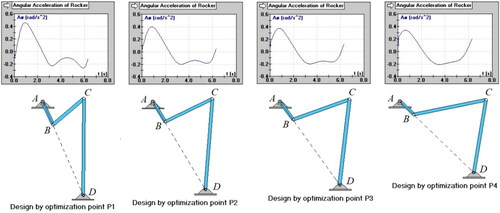
Table 1. Summary of the design results.
Finally, a point that can be of interest is how a preferred solution can be chosen from the four mentioned alternatives. One possible method for this is the TOPSIS (Technique for Order of Preference by Similarity to Ideal Solution) method (Pandey et al., Citation2023). This is a multi-criteria decision-making technique that assumes the preferred alternative should be the one closest to the positive ideal solution (PIS) and farthest from the negative ideal solution (NIS). The general TOPSIS algorithm and calculations applied to this problem are provided in the Appendix. By this method, assuming that the design objectives (transmission angle and smallest link-length ratio) have the same importance level (weight), the TOPSIS algorithm has ranked the alternatives as follows: P3, P2, P4, P1. This ranking would be altered if the weights on the criteria are changed.
8. Conclusion
The paper proposes a novel procedure for bi-objective design of centric crank-rocker mechanisms. The procedure develops a normalized Pareto front where the design criteria are normalized to their limiting values. The normalized values represent the attainment levels of the criteria relative to the ideal (unattainable) solution. Once a point on the normalized front has been selected, the corresponding mechanism dimensions can be computed using the obtained design equations. The provided design example demonstrates that normalization of the Pareto front facilitates more insightful decision-making in the mechanism design process.
Disclosure statement
No potential conflict of interest was reported by the author(s).
Data availability statement
The authors confirm that the data supporting the findings of this study are available within the article.
Additional information
Notes on contributors
Abdullah F. Al-Dwairi
Abdullah F. Al-Dwairi is an associate professor of mechanical engineering. He received his PhD from Saint Petersburg State University of Technology and Design. His research interests include mechanical system dynamics and design, manufacturing technologies, and product design and development.
References
- Ahmadi, B., & Ahmadi, B. (2022). Optimal synthesis of crank-rocker mechanisms with optimum transmission angle for desired stroke and time-ratio using genetic programming. Advances in Mechanical Engineering, 14(10), 168781322211312. https://doi.org/10.1177/16878132221131291
- Al-Dwairi, A., Al-Lubani, S., & Al-Nawafleh, M. (2009). Analytical synthesis of crank-rocker and double-crank mechanisms with minimax link-length ratios. Proc. of the 37th Conference "Advanced Problems in Mechanics," Russian Academy of Science, June 30 – July 5 ( pp. 192–203 ) . Saint-Petersburg, Russia.
- Balli, S. S., & Chand, S. (2002). Transmission angle in mechanisms (Triangle in mech). Mechanism and Machine Theory, 37(2), 175–195. https://doi.org/10.1016/S0094-114X(01)00067-2
- El-Shakery, S., Ramadan, R., & Khader, K. (2020). Analytical and graphical optimal synthesis of crank-rocker four bar mechanisms for achieving targeted transmission angle deviations. Jordan Journal of Mechanical and Industrial Engineering, 14(3), 303–313.
- Fogarasy, A. A., & Smith, M. R. (1998). The influence of manufacturing tolerances on the kinematic performance of mechanisms. Proceedings of the Institution of Mechanical Engineers, Part C: Journal of Mechanical Engineering Science, 212(1), 35–47. https://doi.org/10.1243/0954406981521024
- Funabashi, H., & Freudenstein, F. (1979). Performance criteria for high-speed crank-and-rocker linkages—Part I: Plane crank-and-rocker linkages. Journal of Mechanical Design, 101(1), 20–25. https://doi.org/10.1115/1.3454019
- Gunantara, N. (2018). A review of multi-objective optimization: Methods and its applications. Cogent Engineering, 5(1), 1502242. https://doi.org/10.1080/23311916.2018.1502242
- Han, T., Jiao, L., Lee, J. H., & Yin, J. (2023). A utopia point method-based robust vector polynomial optimization scheme. Journal of Global Optimization, 88 (2), 461–483. https://doi.org/10.1007/s10898-023-01321-9
- Jahan, A., Edwards, K., & Bahraminasab, M. (2013). Multi-criteria decision analysis (2nd ed., pp. 63–65). Elsevier.
- Lee, W.-T., & Russell, K. (2017). Developments in quantitative dimensional synthesis (1970–present): four-bar path and function generation. Inverse Problems in Science and Engineering, 26(9), 1280–1304. https://doi.org/10.1080/17415977.2017.1396328
- Lu, L., Anderson-Cook, C. M., & Robinson, T. J. (2011). Optimization of designed experiments based on multiple criteria utilizing a Pareto frontier. Technometrics, 53(4), 353–365. https://doi.org/10.1198/TECH.2011.10087
- Lun, M., & Leu, Y. (1996). Design of crank-rocker mechanisms with optimum transmission angle over working stroke. Mechanism and Machine Theory, 31(4), 501–511. https://doi.org/10.1016/0094-114x(95)00088-g
- Mutlu, H. (2021). Design of the crank–rocker mechanism for various design cases based on the closed-form solution. Sādhanā, 46(1), 1–11. https://doi.org/10.1007/s12046-020-01529-5
- Nariman-Zadeh, N., Felezi, M., Jamali, A., & Ganji, M. (2009). Pareto optimal synthesis of four-bar mechanisms for path generation. Mechanism and Machine Theory, 44(1), 180–191. https://doi.org/10.1016/j.mechmachtheory.2008.02.006
- Norton, R. L. (2013). Kinematics and dynamics of machinery. Mcgraw-Hill.
- Pandey, V., Komal, & Dincer, H. (2023). A review on TOPSIS method and its extensions for different applications with recent development. Soft Computing, 27 (23), 18011–18039. https://doi.org/10.1007/s00500-023-09011-0
- Rothenhofer, G., Walsh, C., & Slocum, A. (2010). Transmission ratio based analysis and robust design of mechanisms. Precision Engineering, 34(4), 790–797. https://doi.org/10.1016/j.precisioneng.2010.03.010
- Santoro, E. (1992). Global methods in multi-objective optimization and their application to a mechanical design problem. Computers in Industry, 18(2), 169–175. https://doi.org/10.1016/0166-3615(92)90111-y
- Singh, R., Chaudhary, H., & Singh, A. K. (2017). Defect-free optimal synthesis of crank-rocker linkage using nature-inspired optimization algorithms. Mechanism and Machine Theory, 116, 105–122. https://doi.org/10.1016/j.mechmachtheory.2017.05.018
- Valencia-Segura, L. E., Villarreal-Cervantes, M. G., Corona-Ramirez, L. G., Cuenca-Jimenez, F., & Castro-Medina, R. (2021). Optimum synthesis of four-bar mechanism by using relative angle method: A comparative performance study. IEEE Access. 9, 132990–133010. https://doi.org/10.1109/ACCESS.2021.3115444
- Waldron, K. J., Kinzel, G. L., & Kumar Agrawal, S. (2016). Kinematics, dynamics, and design of machinery. Wiley.
- Zhang, X., Tian, Y., & Jin, Y. (2015). A knee point-driven evolutionary algorithm for many-objective optimization. IEEE Transactions on Evolutionary Computation, 19(6), 761–776. https://doi.org/10.1109/TEVC.2014.2378512
Appendix 1.
Ranking of the design alternatives using the TOPSIS method
TOPSIS as one of multi-criteria decision making (MCDM) methods considers both the distance of each alternative from the positive ideal solution (PIS) as well its distance from the negative ideal solution (NIS). The best alternative is the one closest to PIS and farthest from NIS. In our example, we have two design objectives (µmin/µlim and a/alim) and four alternative solutions based on points P1, P2, P3, and P4 of the Pareto front. Ranking of these alternatives based on both objectives by TOPSIS algorithm involves the following steps.
Step1: Assign weights wi to the design objectives based on their importance to the design application. Let us assume here that they have the same weight. So we have w1 = w2 = 0.5.
Step 2: Construct the evaluation matrix. This is shown in where the table body are the coordinates of points Pi given on in the paper.
Step 3: Normalize the evaluation matrix by dividing each entry by the square root of the sum of squares of all entries of its column. This yields .
Step 4: Construct the weighted normalized evaluation matrix by multiplying each entry by the weight assigned to the objective at its column head. This gives .
Step 5: Determine PIS and NIS
The positive ideal solution (PIS) based on an objective is the alternative that best achieves that objective, while the negative ideal solution (NIS) is the alternative with the lowest level of achieving that objective. From , the PIS by the transmission angle objective is P4 and is P1 by the length ratio objective. Hence, the PIS is (0.283, 0.278). Similarly, the NIS is found to be (0.203, 0.210).
Step 6: Calculate the distances from each alternative to PIS and NIS using the formula of distance between two points. For example, the distance of alternative P1 to PIS is found by calculating the distance between points P1(0.203, 0.278) and PIS(0.283, 0.278), and so on. The calculation results are given in .
Step 7: Calculate the relative closeness Ci of each alternative to the ideal solution by dividing the alternative’s distance from NIS by the sum of its distances from PIS and NIS. The results are given in .
Based on the closeness values Ci, the alternatives are ranked as shown in the last column of . This ranking would change if the objective weights are modified.
Table A1. Evaluation matrix.
Table A2. Normalized evaluation matrix.
Table A3. Weighted normalized matrix.
Table A4. Distances to PIS and NIS.
Table A5. Closeness to ideal solution and ranking.