
 ?Mathematical formulae have been encoded as MathML and are displayed in this HTML version using MathJax in order to improve their display. Uncheck the box to turn MathJax off. This feature requires Javascript. Click on a formula to zoom.
Abstract
There are key issues in temporal relational data modelling such as representation of temporal data, temporal grouping identifiers, primary keys of temporal relations and temporal integrity constraints. Temporal grouping is a fundamental aspect of temporal data modelling and is the basis for the specification and enforcement of temporal integrity constraints. We extend and generalize traditional integrity constraints for the temporal domain by formally defining the temporal grouping identifier and show how it can replace a temporal primary key like a temporal atom, a temporal integrity constraint has a data and a temporal component. We also introduce the notion of consistent evolution of a temporal database that lays the foundation for an efficient implementation of temporal integrity constraints. We also provide clauses that need to be added to SQL for specifying the temporal integrity constraints.
1. Introduction
Many applications require temporal data and the functionality for maintaining and manipulating temporal data is a highly desirable in any commercial database management system. A temporal database has a time dimension and maintains time-varying data in contrast to a conventional database that stores only the current and/or recent data, which is also called a snapshot database. In general, a temporal database is visualized as a sequence of snapshots evolving along a time dimension. In the literature, the term temporal database is loosely used to mean a database that has time support and has at least one time dimension.
There are various aspects of temporal data such as the time at which the data becomes effective (i.e. valid time), or the time the data is recorded in the database (i.e. transaction time) [Citation21]. A database that supports only valid time is called a valid time (historical) database. Similarly, a database that supports only transaction time is called a transaction time (rollback) database. On the other hand, a bitemporal database supports both the transaction time and the valid time.
A common, but simple approach for handling temporal data is to augment a relation with time columns. However, this intuitive solution does not address subtle issues peculiar to temporal data, i.e. comparing database states at two different time points, capturing the periods for concurrent events and accessing to times beyond these periods, handling multi-valued attributes, coalescing [Citation3], temporal grouping [Citation7,Citation8] and restructuring temporal data, etc., [Citation9,Citation23,Citation25]. Therefore, for managing temporal data, extensions to relational data model were proposed by attaching time stamps to tuples or attributes that address these issues in different ways or avoid some of them depending upon the modelling approach used.
Researchers generally approach to integrity constraints in a context that considers temporal data as a snapshot evolving over time. Although, this is a natural and convenient modelling of temporal data it overlooks the totality of temporality causing subtle issues that also manifest themselves in the definition and enforcement of temporal integrity constraints. Therefore, we formalize integrity constraints in the context of temporal grouping. We also elaborate on the implications of allowing different time granularities in enforcing temporal integrity constraints.
Following the early approaches, we also generalize the traditional integrity constraints to multi-state temporal integrity constraints that may be synchronous or asynchronous. A synchronous multi-state temporal integrity constraint is a direct application of an integrity constraint to each state of a temporal database alone whereas an asynchronous one is peculiar to temporal data, and it involves several states of a temporal database at the same time.
As a motivating example consider an employee, Tom who started working on 1/3/2023 with a salary of $95 K and Tom’s data stored in the database on 1/5/2023. At this time, the salaries should be between #35 K and $100 K. Tom got a raise of %10 on 2/2/2023 but this fact cannot be recorded in the database since it causes an integrity violation. Later, it was discovered that yearly inflation adjustment of 7% was not reflected in the database at the end 2022. This adjustment later incorporated into the database at 1/5.2023 valid as of 12/31/2023. Then, Tom’s salary raise is stored in the database on 1/6/2023. Tom also gets another raise of 1% on 2/15/2023 and recorded in the database. Then, on 6/1/2023 the president increases the salary range by 3% which is immediately recorded in the database and extends each employee an across-the-board bonus of $5000. These changes both in data values and integrity constraints need to be handled in the database as we clearly observe them in the example that addressed in the remainder of the article.
The focus of the paper is temporal integrity constraints in temporal relational databases. Contributions of our paper can be listed as follows.
We formalize temporal integrity constraints in both tuple and attribute time stamping in a comparative framework and provide relational algebra expressions. Thus, it is a formal and compressive treatment of temporal relational integrity constraints.
We propose and define temporal grouping identifier as a temporal integrity constraint and show how a temporal grouping identifier may replace the traditional concept of primary key in a temporal relation. The concept of temporal grouping identifier has significant implications for the implementation of temporal databases as elaborated in the conclusion section of the article.
We also represent a temporal integrity constraint as one unit of composite data, i.e. a temporal atom (defined below) and likewise a temporal integrity constraint has an integrity (data) component and a time component. The integrity component changes over time and hence gives rise to the notion of consistent evolution of a temporal database.
We propose to store temporal integrity constraints in temporal relations with tuple and attribute time stamping. We also generalize the temporal integrity constraints for the case of bitemporal relations and formally define the clauses that need to be added to the Create Table statement of SQL.
2. Previous research
The terms, temporal grouping and temporal grouping identifier were coined by Clifford, Croker and Tuzhilin to indicate the set of values (tuples) that form the history of an object or a relationship [Citation7]. A temporal grouping identifier is an attribute(s) in a temporal relation that groups the related temporal data. Temporal grouping manifests itself differently in attribute and tuple time stamping. In tuple time stamping, the history is broken into several tuples, but these tuples all have the same temporal grouping identifier value.
The notion of temporal grouping appeared early on in several articles, both in attribute and tuple time stamping. In attribute time stamping, a nested relation keeps the entire history of an object or a relationship in one tuple only, i.e. a temporally grouped tuple [Citation6,Citation9,Citation24]. In tuple time stamping, a tuple represents the history of each attribute value for an object [Citation21]. In contrast to temporal grouping that collects the history of an object in one tuple or in a group of tuples, in a weak relation [Citation9], timestamps of tuples are a subset of the history of an object. Naturally, weak relations occur in attribute and tuple time stamping, and have implications for the maintenance of the integrity constraints.
Temporal functional dependencies have been widely studied and traditional functional dependencies have been extended to the temporal domain [Citation2,Citation11,Citation15,Citation22,Citation29]. If the same functional dependency holds in all the states (snapshots) of a temporal database it is called a temporal functional dependency [Citation15,Citation29]. Similarly, an attribute(s) is a temporal primary key if it is also a primary key in all states of a temporal relation [Citation11,Citation15,Citation22]. Also, functional dependencies that hold in a database that does not have a time dimension turn into multi-valued dependencies in a temporal database [Citation25]. In tuple time stamping, the temporal grouping identifier does not functionally determine the attributes of a temporal relation and hence cannot serve a primary key. The temporal grouping identifier and either Start or End, one of the attributes representing the time interval [Start, End] may serve as a primary key [Citation19] provided that the relation is temporally grouped [Citation7]. However, even if the functional dependency of the temporal grouping identifier with Start or End attributes hold, a temporal relation may not necessarily be grouped.
Gadia introduced weak relations for storing temporal data, whose snapshots at all the time instances are the same [Citation9,Citation11]. Moreover, a weak relation may have multiple versions of history where one of them is the true version that is designated by anchoring. Anchoring also serves for temporal grouping, changes in the primary key attributes values, and restructuring a temporal relation with respect to other attribute(s) [Citation10]. However, in a weak relation, two separate attribute values for an attribute in two different tuples with overlapping validity periods violates the functional dependency in a state of the temporal database. This is also the case for multi-valued attributes.
Dynamic functional dependencies are generally explored in transaction time databases. A dynamic functional dependency holds for the attributes that change concurrently [Citation29] or for the changes in attribute values from one state of the database to its consecutive state [Citation28]. There are other proposed definitions for temporal dependencies as well. A temporal functional dependency may also specify that an attribute whose values are fixed with respect to another attribute over time, for instance, the account balance is always expressed in the same currency [Citation29]. Temporal dependencies and time granularities were explored in [Citation1,Citation13]. A temporal dependency does not allow changes within the specified time granule regardless of its coarseness [Citation1].
A treatment of the valid time integrity constraints can be found in [Citation2,Citation4,Citation12,Citation15,Citation22]. Snodgrass defines sequenced and non-sequenced integrity constraints [Citation22]. The same integrity constraint applies on states of a temporal database in sequenced integrity constraints whereas a non-sequenced integrity constraint applies on multiple states of a temporal database. These constraints correspond to our synchronous and asynchronous multi-state integrity constraints. Well-known examples of sequenced integrity constraints are existence (primary key) integrity and referential integrity. Efficient implementation methods for the sequenced existence and sequenced referential integrity are explored in [Citation30]. Bohlen studies valid time integrity constraints and develops a taxonomy of the integrity constraints according to the temporal support, valid time and transaction time dimensions. He identifies intrastate and interstate integrity constraints within valid time that are the same as our synchronous and asynchronous multi-state integrity constraints. Chomicki calls single- and multi-state integrity constraints within transaction time database as static and dynamic (temporal) integrity constraints, respectively [Citation4]. For enforcing temporal integrity constraints, he augments every database state with an auxiliary relation that contains the historical information whereas we keep the entire history. Chomicki and Toman express temporal integrity constraints in first-order temporal logic along with efficient implementation methods [Citation5]. They also provide translations of integrity constraints defined in temporal logic to equivalent SQL statements. Naturally, enforcement of temporal integrity constraints incurs a heavy overhead which can be alleviated by following certain coding patterns at the application interface [Citation31].
Major database vendors added temporal extensions to their products. SQL 2011 standard includes temporal features that add a period made up of two timestamps as metadata to tables for implementing valid time, transaction time and bitemporal tables [Citation16]. Thus, it stays within the realm of traditional relational theory for backward compatibility. Temporal extensions to XML are also widely explored. An extension reported in [Citation20] adds transaction time to edges of the tree that represents a temporal XML document and verifies its temporal consistency. The temporal consistency verification is similar to our temporal existence dependency constraints. There is a vast body of research on temporal integrity constraints in deductive and object-oriented databases [Citation16,Citation19]. Creation time and deletion time integrity constraints are limited versions of temporal integrity constrains [Citation16].
3. Representing temporal data
U is the set of all atomic values such as real, integers, character strings and the value null. Some values in U represent time and T denotes the set of these values. We call (T, ≤) the time domain and T is a total order under ‘≤’ relationship. It can be represented by integers (I) or real numbers (R). For the sake of simplicity we assume that time values range over the integers 0, 1 … now. Now is a special symbol that represents the current time. The value of now changes accordingly as the clock ticks. In the context of time, any subset of T is called a temporal set. A temporal set that contains consecutive time points {ti, ti + 1, … ti + n} may be represented either as a closed interval [ti, ti + n] or as a half-open interval [ti, ti + n + 1). A temporal element [Citation9] is the union of disjoint maximal intervals and is a compact representation of a temporal set.
We assume that different time granularities in a temporal relational database are allowed. We also adopt the definition given in [Citation1] for time granularities that maps the coarser time granularities to a sequence of integers. Time-varying data is commonly represented by time-stamping values. The timestamps in any time granularity can be time points [Citation6,Citation7,Citation27], time intervals [Citation21], temporal sets [Citation24] and temporal elements [Citation9,Citation15].
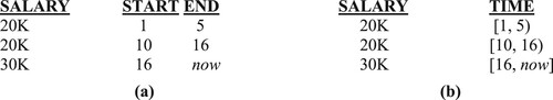
Figure gives an example where time points, intervals, temporal elements and temporal sets are used as attribute timestamps. Each value in Figure is a temporal atom that consists of a salary value and its time reference. Figure depicts two alternative representations in tuple time stamping for the salary data of Figure . Figure .a is a relation that is augmented with two columns to represent the beginning and end instants of a time interval whereas Figure .b directly uses an interval as a base data type. There are also many other possible instances of the relations in Figure and 2 in the form of weak relations [Citation9,Citation11]. Time points, intervals and temporal elements are all needed in temporal query languages. They all enhance the expressive power and the ease of use of a temporal data model and its query languages.
Figure 1. Attribute timestamping. (a) Time points, (b) Intervals, (c) Temporal element, (d) Temporal set.
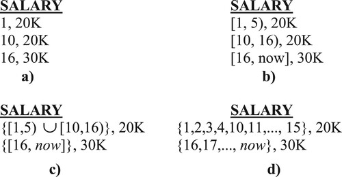
Figure 2. Tuple timestamping. (a) Two time columns, (b) Interval data type.
The representation in Figure is a generic representation of temporal data. The timestamps can be considered as the valid time or the transaction time, each with its own semantics. In a slightly different representation, we can add both transaction time and the valid time to a temporal atom that we will examine in Section 7.
Using time points cannot capture the full extent of the temporal reality unless every time point is listed in a temporal relation, otherwise it may require special null values to correctly determine the validity period of a value [Citation6,Citation7]. However, handling these null values in a query language is not straightforward.
4. Temporal grouping
Temporal data that belongs to an object or a relationship forms a temporal group. Let A be an attribute of an object or a relationship, say o and {a1, a2, … , an} be the set of its values and their time references over o’s life span. The set {a1, a2, … , an} is a temporal group. Temporal grouping is realized differently in attribute and tuple time stamping. Figure shows some employee data in EMP relation by using attribute time stamping whereas Figure gives the same data in tuple time stamping by using three separate relations, EMP_N, EMP_D and EMP_S [Citation7,Citation15,Citation17,Citation21]. The first tuple in Figure contains the entire history for Tom. The set {<[10,15), 20K>, <[15,17), 25K>, <[17,now], 30K>} is the temporal group for the salary attribute and the set {<[10,12), Sales>, <[14,18), Mktg>} is the temporal group for the department attribute. A temporal group is broken to several tuples in tuple time stamping as seen in Figure . For instance, the salary temporal group for Tom is broken to three separate tuples as seen in EMP_S of Figure (c), the first tree tuples have the same E#, namely 121 and is the temporal group representing the salary history of Tom.
Figure 3. The EMP relation in attribute time stamping.
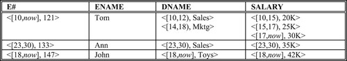
Figure 4. The EMP relation in tuple time stamping. (a) EMP_N Relation, (b) EMP_D Relation, (c) EMP_S Relation.

The EMP relation in Figure is a unique temporally grouped representation of the employee data where each tuple contains the entire history of an employee [Citation6,Citation7,Citation9]. There are many other representations of the same data that can be obtained by taking subsets of temporal sets and creating several tuples for the same employee (weak relations [Citation9]). Weak relations can be converted to an equivalent unique relation by coalescing [Citation3]. Note that weak relations may occur in tuple time stamping too. In EMP_D and EMP_S relations, a tuple may be replaced by several tuples whose time reference is a subset of the original tuple. It is usually assumed that only temporally grouped relations are stored in a temporal database. Therefore, temporal grouping is very useful in handling temporal data [Citation7]. In fact, proper grouping of data in other application domains are also very useful [Citation18].
4.1. Temporal functional dependency and primary key
A functional dependency that holds in all the states (snapshots) of a temporal database is called a temporal functional dependency [Citation11,Citation15,Citation22,Citation29]. In other words, temporal functional dependency X →T Y holds if functional dependency X → Y holds at every snapshot relation defined over a temporal relation. Similarly, attribute(s) X is a temporal primary key for the temporal relational scheme R if X is a primary key for every snapshot defined over R [Citation11,Citation15,Citation22]. This definition applies to tuple and attributes time stamping. In attribute time stamping, snapshots can be derived for each time point from a nested temporal relation. However, in each tuple the temporal primary key stay constant, and other temporal attributes should have only one value at a database state. Moreover, the nested temporal relation needs to be homogenous [Citation9] otherwise, a snapshot may contain null values and the functional dependencies may no longer hold in the presence of the null values. This problem does not occur in tuple time stamping since a temporal relation in attribute time stamping is by definition is homogenous. However, it manifests itself in the enforcement of the referential integrity and we will discuss it in Section 5.2.
A temporal primary key defined in this sense is a straightforward extension to temporal relations, however, it is quite different than the traditional primary key of a relation since it cannot provide the functionally of a primary key. Firstly, it is not unique in tuple time stamping and to make it unique it is augmented with time attributes. In attribute time stamping, primary key need to be redefined because of the set valued attributes. Secondly, it cannot support data maintenance operations as provided by a primary key. Thirdly, a commercial database may not support it.
4.2. Temporal grouping identifier
Definition 4.1 a:
A temporal grouping identifier (TGI) is the attribute(s) that temporally group temporal data in a temporal relation; b: It multi-determines the temporal attribute and time combinations on a canonical 1NF relation (explained below) that is equivalent to a temporal relation.
We examine the cases of tuple time stamping and attribute time stamping separately, and we use multi-valued dependencies for defining temporal grouping identifiers. However, defining multi-valued dependencies is not straightforward on temporal relations (1NF or nested) since they are more complex than traditional relations. We define the multi-valued dependencies on an equivalent canonical 1NF relation that has an additional time column and contains attribute values at every time point the relation is defined. It is obvious that such a relation is not stored in a temporal database; we use is as a theoretical base for our definitions.
Let C(A1, A2, … ,An, T) be a canonical temporal relation scheme over the time interval [l, u) where A1, A2, … ,An, are attribute names and T is a time attribute. Define Rk(A1, A2, … ,An, T) be a relation scheme (that has the same scheme as C) at time point k. Its instance at time point k (k is in interval [l, u)) contains tuples where value of attribute T is k. Then, instance of C = ∪ Rk where k is in [l, u). Simply C is the union of relation instances at each time point in the interval [l, u).
First we will examine the case of tuple time stamping. Let TTS(A1, A2, … ,An, Start, End) be a temporal relation scheme in tuple time stamping. In general, TTS would contain an attribute, say A1 that does not change with time, and one or more temporal attributes (A2, … ,An) that may change over time, but synchronously.Footnote1 Moreover, assume that A1 is part of a temporal primary key in TTS. In general TTS contains two attributes: the temporal primary key, A1 and a time-varying attribute, A2 (or the others). The attribute combinations (A1, Start) or (A1, End) could be considered as the (temporal) primary key of the relation scheme TTS. However, neither (A1, Start) nor (A1, End) groups the temporal values that belong to the same object. It indicates the value valid at a time point.
Theorem 4.1:
Let the relation TTS(A1, A2, … ,An, Start, End) be a temporal relation. There is a canonical temporal relation TTSC(A1, A2, … ,An, T) that is semantically equivalent to TTS. Attribute T contains all the time points in the interval [Start, End).
Proof:
For every tuple in TTS create a family of tuples in TTSC by repeating the TTS tuple for each time point in its validity interval. A temporal relational algebra expression can easily be formulated to do itFootnote2 [Citation24,Citation25].
In TTSC, the multi-valued dependency A1 →→ (A2, … ,An, T) holds trivially or A1 →→ (A2, … ,An) is a trivial embedded multi-valued dependency. Therefore, A1 is a temporal grouping identifier. It temporally groups the temporal values of (A2 … , An). Figure depicts two such sample relations, EMP_D and EMP_S for the EMP relation of Figure . In each of these relations E# is a temporal grouping identifier. Tuples with the same E# value represent the data that belong to an employee. An interesting observation is on how functional and multi-valued dependencies generalize to the temporal dimension. If TTS has a multi-valued attribute (say A2) A1 can not a temporal primary key. Attributes A1 and A2 are needed for the temporal primary key. However, A1 is still the temporal grouping identifier and it temporally groups the attributes that are involved in multi-valued dependencies in a temporal relation.
We now examine the case of attribute time stamping. Let ATS(A1, A2, … ,An) be a nested temporal relation scheme in attribute time stamping. Each attribute Ai in ATS is a constant or a temporal attribute. For the sake of simplicity, lets also assume that A1, is a constant attribute that can form a primary key [Citation18] and A2 … , An are time-varying attributes.
Theorem 4.2:
For the relation ATS(A1, A2, … ,An) there is an equivalent canonical 1NF relation, ATSC(A1, A2, … ,An, T) where Ti is the time attribute for the attribute Ai, i = 2, … ,n.
Proof:
To obtain ATSC we first unnest [Citation24]. Each time varying attribute A2, … ,An and then decompose the temporal atoms to their value and time components. The resulting relation is similar to TTS and by Theorem 1 it can be converted to ATSC [Citation24,Citation25].
In ATSC, if A1 →→(Ai,T) holds for i = 2, … ,n; then, A1 is a temporal grouping identifier for ATS. Even if ATS has other constant attributes (single valued or multi-valued) our definition of the temporal grouping identifier still holds since a functional dependency is a simpler form of multi-valued dependency. Therefore, we may slightly modify the definition of a temporal grouping identifier to include functional dependencies in the case of attribute time stamping where nested relations are used. As an example, consider the EMP relation given in Figure . It is equivalent to EMP_ATSC(E#, ENAME, DNAME, SALARY, TIME) where TIME contains the time points representing the time references of the attributes DNAME and SALARY. In EMP_ATSC, the following dependencies hold:
E# → ENAME
E# →→ (DNAME, TIME)
E# →→ (SALARY, TIME)
In a temporal database we replace the traditional primary key with a temporal grouping identifier which functions much like a temporal primary key but has more functionality. Defining traditional primary keys with the help of time attributes creates subtle problems such as weak relations or representing the same tuple with different time values that are all syntactically legal but may not be semantically correct. Table compares primary keys and temporal grouping identifiers in temporal context. Moreover, temporal grouping identifier is useful in manipulating temporal data, especially in calculation of the temporal aggregates or top-k queries [Citation14,Citation22].
Table 1. Operations for PK and TGI.
4.3. Relationships
Now we examine temporal grouping in relationships. Consider a relation representing the relationship between employees and projects, EP(E#, P#, TOOL) where no time is considered.
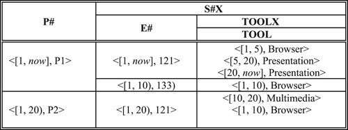
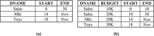
The temporal version of EP relation given in Figure depicts the tools an employee uses in a project over time, i. e. tool history. For the sake of simplicity let us assume that an employee uses one tool in a project at a time. In the temporal version of EP, it is augmented with two additional time attributes: START and END (to add a temporal dimension to EP). Composite attributes (E#, P#) is a temporal grouping identifier for EP. Figure depicts EP relation in attribute time stamping which is a nested relation. The attribute TOOLX is a set of time-stamped tool values an employee uses for a project. Clearly (E#, P#) is a temporal grouping identifier for this relationship. Moreover, this relationship can also be embedded into employee or project relations as exemplified in Figures and . Figure shows an employee and all the projects for which that employee worked, whereas Figure represents projects and their employees. Note that in Figures and the other attributes of employees and projects are not included for the sake of brevity. We also assumed that there is a PROJECT relation whose primary key is P#. In EP relation given in Figure , E# and P# are at the same level whereas in the relations given in Figures and , they are at different levels. P# is a temporal grouping identifier within E# that is another temporal grouping identifier and vice versa.
Figure 5. EP Relation in tuple time stamping.
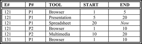
Figure 6. EP Relation in attribute time stamping.
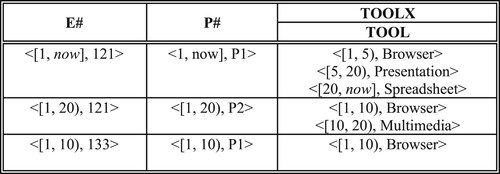
Figure 7. EP Relation embedded in EMP relation.
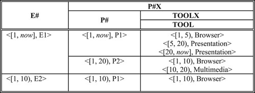
Figure 8. EP Relation embedded in PROJECT relation.
5. Temporal integrity constraints
Each object, such as an employee, exists in a certain period of time, which is a subset of [0, now]. We call this period the object's life, denoted as l(o) for the object o. Part or all of an object's life is represented in a database and we call it its lifespan, ls(o). Hence, ls(o)l(o). An object may have constant and time varying attributes. One or more of the constant attributes, if they are unique, serve as a temporal grouping identifier. Thus, employee number is a temporal grouping identifier and can be represented with no timestamp where its time reference is implied as l(o). It can also be stored with an explicit time reference in the form of a temporal atom, <(o.E#, ls(o)>,.
A traditional database keeps the current snapshot of the reality in which the integrity constraints are enforced. These are single-state integrity constraints (also called static integrity constraints [Citation4]) since they apply to the data valid at an instance of time. Single-state integrity constraints are directly applicable to any snapshot (state) of a temporal database. On the other hand, multi-state integrity constraints apply on several snapshots of a temporal database. There are two types of multi-state integrity constraints. A synchronous multi-state integrity constraint applies to several database states in sequence. In other words, it is a single-state integrity constraint that applies to each of the several database states separately. This is the same as the sequenced interpretation of integrity constraints in [Citation22]. An asynchronous multi-state integrity constraint applies to several states of the database at different times. Given the time instants t1, t2 and t1≠ t2 an asynchronous multi-state integrity constraint involves the data values valid at t1 and t2. Naturally, a multi-state integrity constraint may involve any number of time instants. A special kind of asynchronous multi-state integrity constraint is called transition or dynamic integrity constraints and involves two consecutive states of the database [Citation4,Citation28]. A temporally invariant integrity constraint holds in all states of a temporal database without ever changing. Temporal existence integrity and temporal referential integrity are examples of temporally invariant integrity constraints. The other type of integrity constraints such as domain constraints may change as the time progresses.
Much like a temporal atom a temporal integrity constraint has two components: an integrity constraint (data component) and its time reference (time component). The data component of a temporal integrity constraint may be a synchronous or an asynchronous multi-state integrity constraint. The temporal component of a multi-state integrity constraint is peculiar only to the temporal databases. It is a direct consequence of the fact the attributes of an object may change over that object’s lifespan. In the following paragraphs we will apply this conceptualization of temporal integrity constraints to temporal databases.
Let Ct be a set of integrity constraints in a temporal database at time t: Ct = {c1, c2, … , cn}. Each constraint ci has a validity period as well as a transaction time that designates when the integrity constraint is recorded in the database. Since we deal with valid time databases, transaction time defaults to now. We represent temporal integrity constraints as temporal atoms, in the form of <[l, u), ci>, where c1 is the constraint identifier and [l, u) is the time reference designating when the constraint holds and needs to be enforced. Temporally invariant integrity constraints do not have a temporal component since they do not change. Their validity period is the lifespan of the relation (database) they are enforced in.
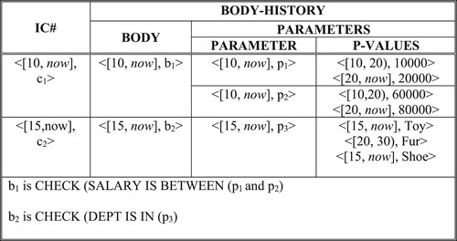
An integrity constraint ci has a body (b) and may have one or more parameter values (pi), i.e. ci ((b1, (p1, p2, … , pn)), … ,((b2, (p1, p2, … , pm)))). As time progresses the body and/or the parameter values may change. However, the parameter values change only within a constraint body. There are two ways to deal with these changes. One possibility is to reformulate a new integrity constraint for each change in the body and/or in the parameter values. These would be independent constraints. For the parameters in a constraint no time is specified and the time reference of the body and the parameters default to the validity period of the constraint. The other possibility is to define the body and parameters of an integrity constraint as a set of temporal atoms. The constraints may be stored in a temporal relation. Figure gives an example of a nested temporal relation that stores integrity constraints.
Figure 9. Nested temporal relation that stores integrity constraints.
Let Cnow - 1 be a set of integrity constraints and TDBnow - 1 be the state of a temporal database before the current time instant. TDBnow – 1 satisfies the integrity constraints included in Cnow - 1.
Definition 5.2:
Consistent evolution of a temporal database, a temporal database evolves from a consistent state TDBnow – 1 at time now – 1 to a new consistent state TDBnow at time now and TDBnow satisfies Cnow. In the one time unit from now – 1 to now a transaction that changes the state of the database may occur or a change in Cnow – 1 occur. The state of the database at time now is consistent with the integrity constraints in Cnow.
Existence and referential integrity are essential constraints in relational databases. Existence integrity constraints assert that a primary key attribute may not have nulls whereas referential integrity constraints assert that only existing objects (entities) can form relationships during their lifespan. Following paragraphs explain how these constraints are handled in a temporal database.
5.1. Temporal existence integrity
Table lists the requirements to enforce a temporal existence integrity constraint. Rule TEI1 of temporal existence integrity requires that attributes that form the temporal grouping identifier may not have null values in any part of the object's life lifespan (ls(o)). Thus, the traditional existence integrity (primary key) constraint directly applies to a temporal relation as a synchronous multi-state temporal integrity constraint.
Table 2. Temporal existence integrity constraint.
Temporal grouping entails a group of tuples representing the history of an object and is an aspect of temporal existence integrity. Rule TEI2 enforces that the values of a temporal grouping identifier may not change. Rule TEI2 is peculiar to temporal data and does not have a counterpart in traditional databases. In a traditional database if the primary key values are not allowed to change; this is enforced as a business rule, not as a data modelling construct. If primary key values are allowed to change, the database system does not track the changes. It is handled as a deletion followed by an insertion. However, rule TEI2 is an asynchronous multi-state integrity constraint since it requires that the temporal grouping identifier values at different time instants in object’s lifespan should not change. Moreover, in tuple time stamping the temporal grouping identifier, if allowed to change, (for instance E#), loses its capability to group temporal data, whereas no such loss occurs in attribute time stamping since the former and the new values of the temporal grouping identifier can be stored in the same set [Citation7]. For enforcing rule TEI2, updates on the temporal grouping identifier may not be allowed. Insertion of a new tuple having a temporal grouping identifier value that matches an existing temporal grouping identifier value may not be allowed either.
The rules TEI3 – TEI6 involve the time component of a temporal existence integrity constraint. Therefore, the lifespan of a tuple (objects) needs to be stored in the database since it is essential data required for enforcing integrity constraints in a temporal database. Naturally, it cannot be null (Rule TEI3). In attribute time stamping, lifespan of a tuple can be stored as the time reference of the TGI, e.g. the E# attribute in EMP relation of Figure . When a relationship is embedded in a relation (such as Figures and ), temporal grouping integrity is enforced in both the outer relation and in the embedded relation. In case of tuple time stamping, the temporal database should include lifespan of objects. Thus, we need to add a separate lifespan relation, EMP_LS(E#, Start, End) to store the lifespan of each employee (Figure ) to represent EMP relations of Figure (hence Figure ). Note that lifespan data cannot be deduced from the EMP_D or EMP_S relations in Figure since they contain data about department and salary attributes and their time reference can only be a subset of an employee’s lifespan, i.e. rule TEI4. Therefore, in tuple time stamping there is no other solution except adding a relation like EMP_LS to the database. Rule TEI5 disallows weak relations [Citation9] that were discussed in Section 4.1. Rule TEI6 requires that time reference of the attribute values in a temporal group do not intersect and thus partition the time reference of the temporal group.
Figure 10. EMP_LS in tuple time stamping.
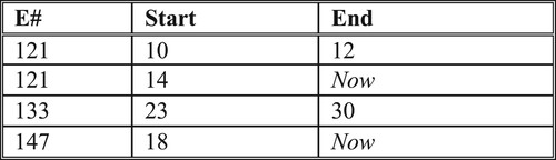
Table gives a procedure for enforcing rule TEI4 of temporal existence integrity. Granularity conversion is needed in step 2 and step 5 of the procedures for attribute and tuple time stamping; respectively in case different time granularities are used in these relations. Naturally the finer granularity among the involved attributes is the base granularity to which the others are all converted.
Table 3. Enforcing time component of temporal existence integrity.
Let R be the prefix in a family of temporal relations. R_LS(TGI, Start, End) stands for the life span relation (for instance, EMP_LS) and R_Ai (TGI, Ai, Start, End) for I = 1, … ,n be an attribute relation (for instance EMP_SALARY). Algorithm Verify_Time_TEI_TTS enforces the condition that Rule TEI4 of the temporal existence integrity is not violated in tuple time stamping.
Table
Let R be a temporal relation in attribute time stamping. It is R(TGI, A1, … ,An) where TGI is the temporal grouping identifier and A1, … ,An are its temporal attributes. Algorithm Verify_Time_TEI_ATS verifies the time component of temporal existential integrity.
Table
5. 2. Temporal referential integrity
Referential Integrity requires that values in the referencing relation should exist in the referenced relation. The same notion applies to a temporal database and temporal referential integrity is a synchronous multi-state integrity constraint which is applied at every database state. Table lists the rules for the temporal referential integrity constraint. This is the same as the notion of a sequenced integrity constraint in [Citation22]. For the time component of a temporal referential integrity constraint, time of the foreign temporal grouping identifier (foreign key attribute in the non-temporal case) in the referencing table should be a subset of the time of the attribute in the referenced table that is the temporal grouping identifier, (Rule TRI2). In enforcing rule TRI2, first we need to synchronize the times of attributes in the referenced and the referencing relations and then we compare the values to verify that the referential integrity holds. Below we give two algorithms for enforcing temporal referential integrity constraints for attribute and tuple time stamping. If weak relations are not allowed [Citation9] there is no need for the synchronization step. The examples we used in this paper do not require the synchronization step.
Table 4. Temporal referential integrity constraint.
Let R_LS(TGI, Start, End) stand for the life span relation (for instance, DEPT_LS) and S_A(TGI, A, Start, End) be an attribute relation (for instance EMP_D). Assume that attribute A of S_A references TGI of R_LS. Algorithm Verify_TRI_TTS enforces the requirement that the data and time components of the temporal referential integrity are not violated.
Table
Table
Consider the EMP relation of Figure and the DEPARTMENT relations of Figure , respectively. DNAME in EMP is a foreign TGI since DNAME in DEPARTMENT is the TGI. Algorithm Verify_TRI_ATS enforces a synchronous multi-state integrity constraint, that is, every DNAME value in EMP synchronously appears in some tuple of the DEPARTMENT relation and the time of the former is a subset of the latter; that is, for a tuple e of EMP and a tuple d of DEPARTMENT ls(e[DNAME]) ls(d[DNAME]). In case of tuple time stamping, consider the EMP_D relation of Figure and DEPARTMENT_LS relation of Figure (a). We follow the algorithm Verify_TRI_TT to enforce the condition that the DNAME value in a tuple of EMP_D relation appears in some tuple of the DEPARTMENT_LS relation. Also, the time of a tuple in EMP_D is a subset of the corresponding tuple in DEPARTMENT_LS. Note that there is also a referential integrity constraint between E# in EMP_D and the E# attribute in EMP_LS.
Figure 11. Department relations in tuple time stamping. (a). DEPARTMENT_LS Relation, (b). DEPARTMENT_B Relation.
The second example involves a relationship between employees and the projects they work for. Consider the EP relation given in Figure and let ep be one of its tuples. Also, let e and p be tuples of the EMP and PROJECT relations respectively. E# attribute in EP is a foreign TGI therefore, ls(ep[E#]) ls(e[E#]). So is the case for P#, i.e. ls(ep[P#])
ls(p[P#]). Moreover, the relationship, EP, can only exist during a common time an employee and a project jointly exist; that is ls(ep[E#, P#)
ls(e[E#]) ∩ ls(p[P#]).
Naturally, temporal referential integrity needs to be enforced in relationship relations that involve nesting of attributes. EP relation is embedded in the EMP relation in Figure and therefore temporal referential integrity has to be enforced within the EMP relation. The time reference of temporal grouping identifiers in sub-relations (this appears in P#X sub-relation in EMP relation of Figure ) should be within the time reference of the temporal grouping identifier of the outer relations i.e. E#. This restriction applies on relationships embedded in a relation, Let ep be a tuple of the EMP relation given in Figure , then ls(P# in ep[P#X]) ls(ep[E#]). Deletions are cascaded. If the relationship is deleted than the temporal grouping identifier (P#) in the sub-relation is set to null to indicate the non-existence of the relationship.
In a temporal database, there are interesting constraint combinations which are possibly very expensive to enforce in traditional databases or they are enforced outside of the database application. For instance, the constraint that an employee could only work for the Toy department after working in the Sales department or an employee cannot work in the same department without working in all the other departments are examples of such constraints. Enforcing these constraints together with temporal referential integrity would be more efficient [Citation26].
5.3. Domain constraints
There are also constraints arising from the business rules that need to be enforced against a temporal database. These constraints are enforced as domain constraints on the possible values of domains supported or attribute values in a database, as attribute constraints, or table constraints. Moreover, these constraints may be specified in the form of assertions or triggers. Each constraint has a validity period over which it is enforced. For instance, <[5, now], c1>: an employee’s salary may not be less than the substance level, say $23000. The validity period of this constraint is [5, now] and the database states valid in this period may not violate it. Domain constraints may be single state or multi state and multi state domain constraints may be synchronous or asynchronous.
Temporal existence integrity and temporal referential integrity are applicable on the entire history of a temporal database whereas domain integrity constraints are applicable in the partial or entire history of a temporal database. Moreover, the former constraints are constant whereas the latter constraints may change and evolve.
5.4. Time granularities and integrity constraints
Different time granularities are allowed in temporal relations. However, there is a difference between attribute and tuple time stamping. In tuple time stamping each temporal relation may only have one time granularity even if there are several attributes in it since those attributes change simultaneously at different time granularities, the finer time granularity that is common to all of them will be used as the time granularity in the temporal relation. In this case, due to the data redundancy the temporal relation needs to be decomposed. Moreover, each temporal relation may have a different time granularity. In attribute time stamping, each attribute of a nested temporal relation can be defined with a different time granularity.
If an integrity constraint involves a single attribute its time granularity is irrelevant in enforcing the integrity constraint. On the other hand, if the integrity constraint involves two or more attributes defined with different time granularities enforcing the integrity constraint requires time granularity conversion. For instance, in the temporal referential integrity, the referencing attribute and the referenced attribute may have different time granularities. If these time granularities are compatible [Citation1], adding a simple granularity conversion function to Tables and would be sufficient. The granularity conversion function converts from the coarse granularity to the finer granularity that appears in the constraint. If the time granularities are not compatible the temporal referential integrity constraint may not be enforced.
Table 5. Enforcing temporal referential integrity.
6. Enforcing integrity constraints
A temporal database acquires a new state as the result of data maintenance operations and/or a change in the set of temporal integrity constraints. Even if there is no data maintenance operation at now there may still be a new database state due to changes in the set of integrity rules. At time now, Cnow may include new integrity constraints, there may be changes in the parameters of the existing integrity rules, or some integrity constraints may be dropped. In existing data, there may be violations of newer recently introduced integrity constraints. In this case, the violating data can be determined and handled according to relevant business policies. However, this may turn out to be a complicated operation with heavy overhead.
Enforcing a synchronous multi state integrity constraint is not an expensive operation since it can be done incrementally. Because of the consistent evolution of a temporal database its previous state would satisfy the integrity constraints at Cnow - 1. So, the current state should satisfy the integrity constraints in Cnow - 1 and the newly added constraints at time now. Therefore, considering the current state would be sufficient to verify whether the integrity constraints are satisfied or not. In fact, verifying that changes in the data from state now -1 to now (i.e. TDBnow to TDBnow – 1) against the constraints in Cnow would be sufficient provided that no new constraints affecting the past states are added to Cnow. However, enforcing asynchronous multi-state integrity constraints is an expensive operation since multiple states in the past are required, in addition to the current state of the temporal database. Again, considering that only data values changed in these states reduces the overhead of this operation. Moreover, retroactive changes may also be very costly to enforce the integrity constraints.
Although a temporal database evolves to its current state smoothly, data maintenance operations directed at the past states of a temporal database may be expensive to process. These operations may violate the temporal existence and temporal referential integrity, or domain constraints and thus, all past data that are affected need to be considered.
7. Bitemporal integrity constraints
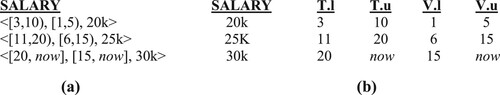
In a bitemporal database both transaction time and the valid time are supported. So, past, present and future data and integrity constraints can be stored in a temporal database. Moreover, retroactive and post-active changes can be made and a record of these changes including the changed and the newly added values are available in the bitemporal database [Citation21]. A bitemporal atom is in the form of < Tt, Vt, v > where Tt, Vt and v are the transaction time, valid time and the attribute value, respectively. It asserts that the value v is valid over Vt and this fact is recorded in the database in Tt. Figure gives a sample bitemporal relation where time intervals are used to represent the transaction time and the valid time. The notations ‘.l’ and ‘.u’ represent the lower and upper bounds of an interval, respectively. Temporal elements or temporal sets can also be used in representing the transaction time and the valid time.
Figure 12. Bitempral atoms. (a) Attribute time stamping, (b) Tuple time stamping.
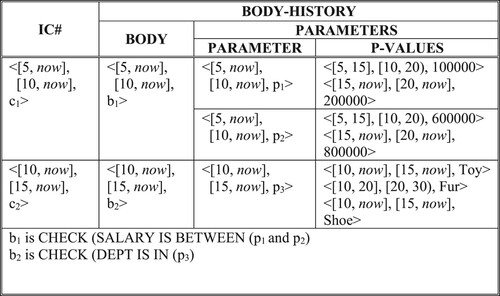
Similarly, we can represent integrity constraints with both a valid time and a transaction time, <[Tt],[Vt], ci >. Bitemporal constraint ci is recorded in the database at the transaction time Tt, and it is enforced during its validity period Vt. A bitemporal integrity constraint ci has a body (b) and may have one or more parameter values (pi), i.e. ci(body, p1, p2, … , pn). The body and the parameter values can be represented as bitemporal atoms as well.
To enforce bitemporal integrity constraints, first the database is rolled back to a given transaction time. The integrity constraints are also rolled back to the same transaction time and it is then verified that integrity constraints hold in that database state. Figure gives a nested relation that stores bitemporal integrity constraints.
Figure 13. Bitemporal integrity constraints.
7.1. Adding temporal integrity constraints to SQL
We augment the Create Table statement in SQL for adding temporal integrity constraints. We provide the definitions for bitemporal integrity constraints. VALIDITY sub-clause is for the valid time whereas RECORDED sub-clause is for the transaction time. Following clauses are added to the Create Table statement:
[CONSTRAINT < Constraint Name > VALIDITY IS < Time Reference > | RECORDED AT < Time Reference > ] TEMPORAL GROUPING IDENTIFIER (<Attribute Name>)
[CONSTRAINT < Constraint Name > VALIDITY IS < Time Reference > | RECORDED AT < Time Reference > ] < Attribute Name > REFERENCES < Relation Name > (<Attribute Name >) [SET NULL | NULL | NOT NULL | CASCADE]
[NOT] MAXIMAL [PERIOD | TEMPORAL ELEMENT]
[NOT] OVERLAPPING [PERIOD | TEMPORAL ELEMENT]
CONSTRAINT < Constraint Name > VALIDITY IS < Time Reference > | RECORDED AT < Time Reference > CHECK < Constraint Body > <PARAMETERS>
<Constraint body > is an SQL statement
<Parameters > are temporal atoms representing the parameter values in the constraint body
8. Conclusion
In this article, we have discussed the representation of temporal data and temporal integrity constraints within the relational data model. We have adopted a comparative approach and considered the two approaches for modelling temporal data: attribute time stamping and tuple time stamping. We have also elaborated on the relationship between temporal grouping identifiers and primary keys in temporal relations and their implications for representing the temporal data and temporal integrity constraints. Temporal grouping is a fundamental concept for temporal database modelling and temporal grouping identifiers function differently in attribute time stamping and tuple time stamping. The inadequacy of the traditional primary key in temporal data modelling is recognized by many researchers who have proposed the concepts of temporal functional dependencies and temporal keys. Temporal keys can only group temporal data for the attributes that are single valued at any time point and they fail in case of multi-valued attributes. Therefore, temporal grouping identifiers are more general and subsume the functionality of temporal keys.
In implementing a temporal database there are two possibilities: (1) Building it on top of a commercial database, (2) Modifying the commercial databases or developing new database software. Alternative 1 is easy to implement and commonly proposed [Citation22]. However, it is cumbersome and suffers from performance problems since the primary key requires additional time attributes to guarantee its uniqueness. Modifying commercial database software is a better alternative to support temporal grouping identifiers. Indexing structures with duplicate values are already available and what is needed is adding the functionally to the requirements of temporal grouping identifier. We believe that this is feasible and the database with the grouping identifier will be useful in other application domains too.
Temporal integrity constraints have two components: a data component and a time component. The former is a generalization of the traditional integrity constraints whereas the time component is peculiar to temporal database. Moreover, traditional integrity constraints are single-state constraints whereas temporal integrity constraints are multi-state constraints and they can be synchronous or asynchronous. Similar to the evolution of data over time we have considered the evolution of integrity constraints over time. Bitemporal integrity constraints have both a valid and a transaction time component.
Our approach to temporal integrity constraints are different than earlier approaches based on temporal logic [Citation4,Citation5] or those that use statement modifiers to specify that the constraint is applied sequentially in all the states of a temporal database [Citation22]. Instead, we introduce the concept of a temporal grouping identifier, and time reference of an integrity constraint (constraint as a temporal atom) in specifying temporal integrity constraints. We apply an integrity constraint during its validity period instead of applying it on every database state.
In our future work, we plan to explore the applicability of our approach for checking the integrity of temporal XML documents [Citation20]. For the implementation of the temporal integrity constraints in valid time and bitemporal databases we plan to explore the feasibility of modifying a commercial database and evaluate its performance. Considering the large volume of temporal data, we expect the implementation will yield interesting insight into the management of integrity constraints in temporal databases. Moreover, the comparative treatment of temporal integrity constraints in attribute and tuple time stamping will be useful for the researchers and the practitioners in modelling and managing temporal data.
Acknowledgements
We would like to thank anonymous reviewers for their valuable comments that significantly improved the paper.
Disclosure statement
No potential conflict of interest was reported by the author(s).
Additional information
Funding
Notes
1 If A2, … ,An, change asynchronously then several temporal relations are defined. Typically, at the extreme case a temporal relation for each attribute Ai is defined.
2 If A2, … ,An, change asynchronously the temporal relations need to be joined. Details can be found in [Citation22].
References
- C. Bettini, S. Jajodia, and S. Wang, Time Granularities in Databases, Data Mining and Temporal Reasoning, Springer Verlag, Berlin, 1998.
- M.H. Bohlen, Valid time integrity constraints, Technical Report TR-94-30, Department of Computer Science, University of Arizona, Tucson, AZ, 1994.
- M. H. Bohlen, R. T. Snodgrass, and M. D. Soo, Coalescing in temporal databases, Proceedings of International Conference on Very Large Databases, 1996, pp. 180–191.
- J. Chomicki, Efficient checking of temporal integrity constraints using bounded history encoding, ACM Trans. Database Syst. 20(2) (1995), pp. 149–186.
- J. Chomicki, and D. Toman, Implementing temporal integrity constraints using an active DBMS, IEEE Trans. Data Know. Eng. 7(4) (1995), pp. 566–582.
- J. Clifford, and A.U. Tansel, On an algebra for historical relational databases: Two views. Proceedings of ACM SIGMOD International Conference on Management of Data, 1985, pp. 247–265.
- J. Clifford, A. Croker, and A. Tuzhilin, On completeness of historical data models, ACM Trans. Database Syst. 19(1) (1994), pp. 64–116.
- J. Clifford, A. Croker, F. Grandi, and A. Tuzhilin, On temporal grouping, in Recent Advances in Temporal Databases, Clifford J. and A. Tuzhilin, ed., Springer-Verlag, Berlin, 1995, pp. 194–213.
- S.K. Gadia, A homogeneous relational model and query languages for temporal databases, ACM Trans. Database Syst. 13(4) (1988), pp. 418–448.
- S.K. Gadia, Temporal databases: A prelude to parametric data, in Temporal Databases: Theory, Design, and Implementation, A.U. Tansel, eds., Benjamin/Cummings, 1993. pp. 28–66.
- S.K. Gadia, and S.S. Nair, Algebraic identities and query optimization in a parametric model for relational temporal databases, IEEE Trans. Knowl. Data Eng. 10(5) (1988), pp. 793–807.
- M. Gertz, and UW Lipeck, Temporal integrity constraints in temporal databases, in Proceedings of the Workshop on Recent Advances in Temporal Databases, J. Clifford and A. Tuzhilin, ed., Springer Verlag Publishing, Berlin, 1995, pp. 77–92.
- I.A. Goralwalla, Y. Leontiev, M.T. Özsu, D. Szafron, and C. Combi, Temporal granularity: Completing the puzzle, J. Intell. Inf. Syst. 16(1) (2001), pp. 41–63.
- F. Li, K. Yi, and W. Le, Top-k queries on temporal data, VLDB J. 19(5) (2010), pp. 715–733.
- C.S. Jensen, R.T. Snodgrass, and M.D. Soo, Extending the existing dependency theory to temporal databases, IEEE Trans. Knowl. Data Eng. 8(4) (1996), pp. 563–582.
- K. Kulkarni, and J.-E. Michels, Temporal features in SQL: 2011, SIGMOD Rec. 41(3) (2012), pp. 34–43.
- N. Mahmood, A. Burney, and K. Ahsan, A logical temporal relational data model, IJCSI Int. J. Comput. Sci. Issues 7(1) (January 2010), pp. 1–9.
- Z.M. Ozsoyoglu, and L.-Y. Yuan, A new normal form for nested relations, ACM Trans. Database Syst. 12(1) (1987), pp. 111–136.
- D. Plexousakis, Compilation and simplification of temporal integrity constraints, Rules in Database Systems, LNCS 985 (1995), pp. 260–276.
- F. Rizzolo, and A.A. Vaisman, Temporal XML: Modeling, indexing and query processing, VLDB. J. 17 (2008), pp. 1179–1212.
- R. Snodgrass, The temporal query language Tquel, ACM Trans. Database Syst. 12(2) (1987), pp. 247–298.
- R. Snodgrass, Developing Time Oriented Applications in SQL, Morgan Kaufmann, 2000.
- A.U. Tansel, J. Clifford, S.K. Gadia, S. Jajodia, A. Segev, and R.T. Snodgrass, Temporal Databases: Theory, Design, and Implementation, Benjamin/Cummings, Red Wood City, CA, 1993.
- A.U. Tansel, Temporal relational data model, IEEE Trans. Knowl. Data Eng. 9(3) (1997), pp. 464–479.
- A.U. Tansel, and E. Tin, Expressive power of temporal relational query languages, IEEE Trans. Knowl. Data Eng. 9(1) (1997), pp. 120–134.
- A.U. Tansel, Temporal data modeling and integrity constraints in relational databases, Proc. ISCIS (2004), pp. 459–469.
- D. Toman, Point-based vs. interval-based temporal query languages, Proc. ACM PODS (1986), pp. 58–67.
- V. Vianu, Dynamic functional dependencies and database aging, J. ACM 34(1) (1987), pp. 28–59.
- J. Wijsen, Temporal FDs on complex objects, ACM Trans. Database Syst. 24(1) (1999), pp. 127–176.
- L. Wei, R.T. Snodgrass, D. Shiyan, V.K. Gattu, and A. Kasthurirangan, Efficient sequenced temporal integrity checking, Proceedings of the 17th International Conference on Data Engineering, 2001, pp. 131–140.
- H. ZhangH. Beng, K. Tan, L. Zhang, X. Lin, X. Wang, C. Zhang, and H. Mei, Checking enforcement of integrity constraints in database applications based on code patterns, J. Syst. Softw. 84 (2011), pp. 2253–2264.