
 ?Mathematical formulae have been encoded as MathML and are displayed in this HTML version using MathJax in order to improve their display. Uncheck the box to turn MathJax off. This feature requires Javascript. Click on a formula to zoom.
ABSTRACT
The present work investigated the effect of Zr on the precipitation behavior and mechanical properties of Fe-13.5Cr-4.73Al-2.07Mo-(0.34∼0.45)Nb-(0.65∼0.87)Ta-(0.11∼0.33)Zr (wt. %) alloys. The sheet samples were solution treated at 1473 K for 2 h, and then aged at 1073 K for 0∼24 h. The results show that the addition of Zr significantly refines the grains, postpones the precipitation of Laves phase particles, shifts the precipitation kinetics curve to the right, and prolongs the incubation period of phase transformation. At the same time, the low diffusion coefficient of Zr also delays the coarsening rate of precipitated particles. And the yield strength of 0.1Zr alloy (σYS = 418 MPa, δ = 10%) is significantly higher than that of 0.3Zr alloy (σYS = 375 MPa, δ = 6%), exhibiting more prominent mechanical properties.
Introduction
Fe-Cr-Al alloys have been widely used as a prime candidate for fuel cladding materials due to their prominent mechanical properties and resistances to steam oxidation and corrosion, neutron radiation resistance [Citation1–5]. At present, the mechanical properties of the candidate materials are required to be higher due to the harsh service environment such as high temperature and pressure in the reactor. It is well known that precipitation hardening is an important strengthening mechanism for multi-component alloys, and the shape and size of precipitated phase have an important effect on the mechanical properties of the alloy. For example, the nickel-based superalloy strengthened by precipitation of coherent cuboidal γ′-Ni3Al particles on γ-FCC matrix can achieve good high-temperature mechanical properties [Citation6,Citation7]. Similarly, Fe-Cr-Ni-Al alloy exhibits prominent creep resistance at 973 K by precipitation of coherent B2-NiAl or L21-Ni2AlTi square particles on BCC matrix [Citation8,Citation9]. In Al-Cu alloys, the mechanical properties of the alloys are also significantly improved by precipitation of acicular metastable θ′-Al2Cu phase [Citation10]. For Fe-Cr-Al alloys, their high temperature (HT) strength is benefited from the precipitation of Fe2M Laves phase on the ferritic matrix, rather than the carbides (MC/M23C6), since the latter would be dissolved into the matrix at high temperature [Citation11,Citation12].
In fact, the Laves phase is a topologically dense intermetallic compound with three forms of C14 (MgZn2), C15 (MgCu2) and C36 (MgNi2) [Citation13,Citation14]. Laves phases are usually employed to improve the high-temperature strength and creep resistance [Citation15–17]. For example, a uniform dispersion of coarse Fe2Nb Laves phase particles arranged along the triple junctions of a fine-grained α-Fe matrix after hot-forged at 1423 K in Fe-15Al-5Nb alloy (wt. %) showed a good creep resistance at 973 K [Citation18]. In Fe-Cr-Al alloys, minor amounts of Mo and Nb additions into the ternary alloys could significantly enhance their strength due to a fine dispersion of Laves phase particles especially along grain/subgrain boundaries in the α-Fe matrix [Citation11]. However, when the temperature increases above 1273 K, at which a fuel reactor coolant loss accident occurs, a large amount of Fe2(Mo,Nb) particles would be coarsened and dissolved into the ferritic matrix, leading to softening of the material. In our previous work, the Zr/Ta modified Fe-Cr-Al-Mo-Nb alloy showed good mechanical properties and microstructural stability at high temperature, which is ascribed to the co-precipitation of Fe2M, Fe23Zr6, and core(Fe23Zr6)-shell(Fe2M)-structured particles, rather than Fe2M alone [Citation3]. However, the evolution and precipitation kinetics of Laves phase in these alloys have not been studied. Therefore, on the basis of our previous work, it is of great significance to further study the effect of Zr addition on the precipitation behavior and evolution of Laves phase in Fe-Cr-Al alloys.
The present work comprehensively investigated the influence of Zr on precipitation behavior. The total amount of the particle-forming elements (Nb/Ta/Zr) is fixed as 0.579 at.% and the matching (in molar ratio) among them are further tailored, being Zr/(Nb + Ta) = 1/8, and 1/2, respectively, in which the ratio of Nb to Ta is 1/1. Thus, the designed alloy compositions of Fe-13.5Cr-4.73Al-2.07Mo-(0.34∼0.45)Nb-(0.65∼0.87)Ta-(0.11∼0.33)Zr (wt.% = 13.89Cr-9.38Al-1.15Mo-(0.19∼0.26)Nb-(0.19∼0.26)Ta-(0.06∼0.19)Zr at.%) are listed in . Then, the evolution of precipitated particles with increasing the aging time and the precipitation kinetic characteristics of the second phase will be studied. Finally, the mechanical properties of these designed alloys at room temperature will be measured.
Table 1. Chemical compositions of the designed Fe-Cr-Al alloys (wt.%, weight percent).
Experimental
The chemical compositions of the designed alloys are shown in . Alloy ingots with about 100 g each were prepared by vacuum arc-melting. The purities of the raw metals are 99.99 wt.% for Fe, Al, Zr, 99.5 wt.% for Mo, Nb, Ta, and 99.9 wt.% for Cr, respectively. These ingots were homogenized at 1473 K for 2 h, hot-rolled at 1073 K for several time with a total deformation of about 90%. Then these hot-rolled plates with a thickness of about 1.5 mm were aged at 1073 K for 24 h. In order to study the evolution process of the precipitated phase, the 0.1Zr/0.3Zr alloys (named as S1-0.1Zr and S2-0.3Zr alloys) were solution treated at 1473 K for 2 h, and then aged at 1073 K for 5, 15, 30 min, 12, and 24 h.
The phase constitutions of the alloys at different treatment states were identified using a Bruker D8 X-ray diffractometer (XRD) with a Cu Kα radiation (λ = 0.15406 nm). The microstructures were observed by Olympus optical microscopy (OM), and the Zeiss Supra55 scanning electron microscopy (SEM) with an etchant solution of 20% HF + 10% HNO3 + 70% H2O (volume fraction). The elemental distributions and phase compositions in heat-treated alloy samples were analyzed by the SHIMADZU electronic probe micro-analyzer (EPMA). The precipitated phase structures were further identified by the JEM2100F FEG and Tecnai G2 F30 scanning transmission electron microscopy (STEM) with an energy disperse spectroscopy (EDS), where the TEM samples were prepared by twin-jet electro-polishing in a solution of 10% HClO4 + 90% C2H5OH (volume fraction) at about 243 K. The statistical analysis of the volume fraction at different heat treatments was measured from the SEM morphology images (at least 8 images) using the Image-Pro Plus 6.0 software, in which the volume fraction of particles, f, was estimated by the projected areal fraction Af (i.e. f = Af) in each SEM image and the particles size was estimated by measuring the length and width of the rod-shaped particle and the diameter of the spherical particle, respectively. Uniaxial tensile tests at room temperature were conducted on an UTM5504 Material Test System (MTS) equipped with a muffle furnace. The plate tensile samples have a gauge size of 26.0 × 5.0 × 1.5 mm (length × width × thickness), in which three tensile samples for each heat-treated state were measured with a strain rate of 1 × 10⁻³/s. Microhardness tests were conducted using a HVS-1000 Vickers hardness apparatus under a constant load of 300 g for 15 s, where each alloy sample was tested at least for 10 times.
Results
Microstructural characterization with different aging times
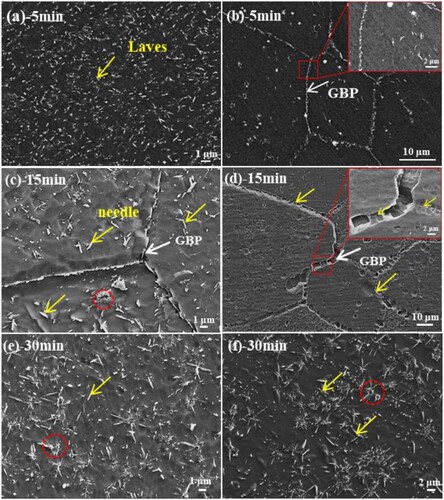
gives the OM and SEM morphologies of the designed alloys after solid solution. The OM image of the designed alloys after solid solution exhibits equiaxed grains ((a,b)) with an average grain size of ∼310 in S1 alloy, ∼ 63 μm in S2 alloy. And the (b) shows that the second phase are all dissolved into the matrix, and some holes can be seen in grain boundaries and inside grains. After aging at 1073 K for 5 min, a large amount of second-phase particles uniformly precipitated from the matrix with a short-rod and spherical morphology, as seen in backscattered electron image of (a,b). The precipitates are distributed at grain boundaries (GBs) and inner grains in the S1-0.1Zr alloy, while in the S2-0.3Zr alloy the precipitates are only distributed at the GBs with a volume fraction of fS1 = 4.66%, and fS2 = 1.19%, respectively. The length of precipitates decreases from 210 nm in S1-0.1Zr alloy to 150∼190 nm in S2-0.3Zr alloys, while the width remains 90∼100 nm, which indicates that the addition of Zr can refine the precipitated particles. In addition, it can be seen that some precipitated phases are distributed along the edges of holes in the S2-0.3Zr alloy ((b)), which indicates that the precipitated phase nucleates preferentially at grain boundaries and the edges of holes. In fact, the nucleation of the Laves phase at these defects would reduce the free energy of these locations. Such a preferential nucleation tendency strongly influences the subsequent Laves microstructure in the alloy. After aging for 15 min, a large number (fS1 = 5.68%) of spherical particles and needle particles (L: 350∼500 nm, W: 100∼150 nm) can be seen in S1-0.1Zr alloy ((c)), while the particles in S2 alloy are still only precipitated at grain boundaries (fS2 = 2.47%). With the aging time increase to 30 min, the short-rod particles are coarsened with the length increase to 500∼600 nm, while the width of the precipitated phase remains at 150 nm ((e,f)). And the volume fraction of the precipitation in designed alloys are fS1 = 6.19%, fS2 = 4.60%. These precipitated particles are nondirectional and multiple precipitations aggregate to form a cluster (marked with the red circle in (e,f)). These clusters of particles tend to diverge around the cavity, which proves that the cavity is the priority nucleation point and significantly affects the shape of the precipitated particles.
Figure 1. The OM of the S1-0.1Zr alloy (a) and S2-0.3Zr alloy (b), and the SEM secondary electron morphology of S2-0.3Zr after solid solution.
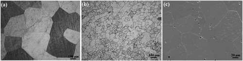
Figure 2. SEM images of the designed alloys at 1073 K aging for different time, (a, c, e): S1-0.1Zr alloy, (b, d, f): S2-0.3Zr alloy.
With the aging time increasing to 12 h, the length of the short-rod precipitates increases to 600∼800 nm, and its width remains unchanged (∼150 nm), with a volume fraction of fS1 = 6.14%, and fS2 = 5.34%, respectively. In the aged alloy, there are obvious precipitation-free zones (PFZ) at grain boundaries, and the width of PFZ gradually increases from 2.4 μm in S1-0.1Zr alloy to 3.8 μm in S2-0.3Zr alloy ((a,b)). Further increasing the aging time to 24 h, the precipitated particles in S1-0.1Zr alloy coarsened significantly and even appeared granular precipitates (marked with the green box in (c)) with an average size of 910 nm long and 250 nm wide in S1-0.1Zr alloy, while the S2-0.3Zr alloy still remains short-rod shaped, with the length of particle size of 710 nm and the width of 180 nm. These particles are distributed uniformly in the inner-grains and GBs, with a volume fraction of about fS1 = 6.62%, and fS2 = 5.89%, respectively. And summarizes the particle size and volume fraction of precipitates in different aging time, which indicated that the increase of Zr element results in the decrease of volume fraction and particle size for Laves phase. And the grain size of S1 alloy after 24 h aging is also larger than that in S2 alloy, which indicates that the increase of Zr can also refine the grains. Moreover, the XRD results in show that these precipitates have a hexagonal Fe2Nb (MgZn2-type) Laves phase structure.
Figure 3. SEM images of the designed alloys at 1073 K aging for 12 and 24 h. (a, c, e): S1-0.1Zr, (b, d, f): S2-0.3Zr.
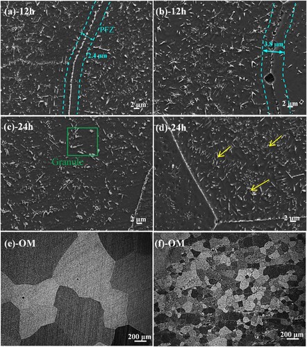
Figure 4. The average volume fraction (a) and the particle size (b) of the precipitates in the designed alloys during long-term aging at 1073 K.
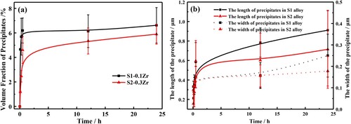
Figure 5. The XRD patterns of the designed alloys after aging for 24 h.
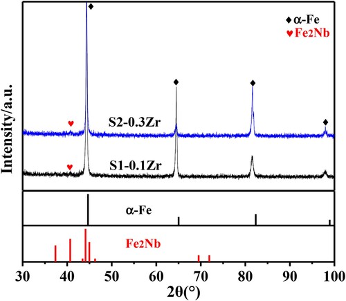
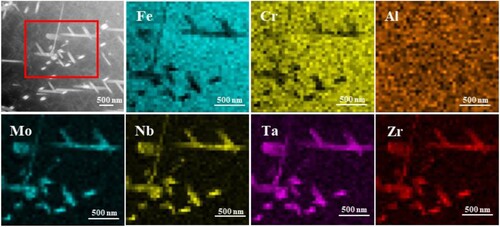
The detailed information on the precipitated particles were achieved further by the TEM analysis as shown in . The precipitated phase in S1-0.1Zr alloy exhibit a hexagonal Fe2M Laves phase (MgZn2-type) structure with a short rod shape and its lattice constant is a = 0.525 nm, c = 0.797 nm after aging for 5 min, as seen in (a). A high dislocation density can be seen in the matrix, and nanoscale precipitated particles (∼10 nm) are distributed around the dislocation, which will significantly strengthen the matrix. In (b), there are a few short rod-shaped precipitates in the matrix of S2-0.3Zr alloy, and the density (∼ 0.38 μm−2) in S2-0.3Zr alloy is significantly lower than that in S1-0.1Zr alloy (∼ 0.47 μm−2). In addition, some nano-particles are also found in the S2-0.3Zr alloy with a size of ∼15 nm, as seen in (e). When the aging time increases to 24 h, the Fe2M Laves in S1-0.1Zr alloy are short rod shape and granular with the number density of 1.42 μm−2. gives the high angle annular dark field (HAADF) image and elemental distributions of the precipitates in S1-0.1Zr alloy, indicating that the precipitates are enriched by Mo, Nb, Ta, and Zr elements. In S2-0.3Zr alloy, the Laves phase (∼1.27 μm−2) precipitates continuously and grows into strips at grain boundaries, while in the grain the Laves phase is mainly small rods ((d)). The high-resolution TEM (HRTEM) image of (f) shows that the short rod-shaped Laves phase have a straight interface with the matrix without an obvious transition region, which indicates that the Laves phase and matrix may have a coherent or semi-coherent relations.
Figure 6. TEM bright-field (BF) images and SAED patterns of the precipitated particles in the designed alloys at 1073 K, (a): S1-0.1Zr-5 min, (b): S2-0.3Zr-5 min, (c): S1-0.1Zr-24 h, (d): S2-0.3Zr-24 h; and the high resolution TEM image of the nano-precipitates in the S2-0.3Zr-5 min (e), and Laves in S1-0.1Zr-24 h (f).
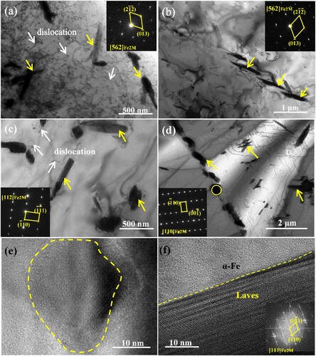
Figure 7. HAADF image and the corresponding elemental maps of the 1073 K-aged S1-0.1Zr alloy by the Super-X EDS.
Mechanical properties
The tensile engineering stress–strain curves of the designed alloys after 24 h aging are shown in (a), from which the yield strength σYS, tensile strength σUTS, and the elongation to fracture δ were measured. The yield strength of S1-0.1Zr alloy (σYS = 418 MPa) is higher than that in S2-0.3Zr alloy (σYS = 375 MPa). The elongation to fracture of S1-0.1Zr alloy (δ = 10%) is also higher than that of S2-0.3Zr alloy (δ = 6%). The microhardness of the designed alloys at different aging times was also measured, as shown in (b). The microhardness values of all alloys in solid solution state are 220∼230 HV. With the extension of aging time, the alloy microhardness peaks appear at 5 min with the value of ∼245 HV in S1-0.1Zr, ∼280 HV in S2-0.3Zr, which may be related to the precipitation of a large number of spherical nanoparticles in the alloy. With further extension of aging time, the microhardness value shows a downward trend and is basically constant in the range of 220∼240 HV after aging 24 h, which may be due to the precipitated particles transformed from nanospherical to needlelike and the strengthening effect significantly reduced.
Figure 8. (a): Engineering stress–strain curves of the designed Fe-Cr-Al-M (M = Mo,Nb,Ta,Zr) alloys at 1073 K aging for 24 h, and (b): microhardness variation of the designed alloys at different states. The fracture surface morphologies of the alloys after aging for 24 h, (c): S1-0.1Zr, (d): S2-0.3Zr.
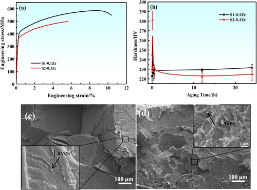
(c,d) shows the typical fracture surface morphologies of the tensile samples. All the alloys show a typical river pattern and there is obvious second phase on the fracture interface, which is a typical brittle fracture ((c,d)). This brittle fracture is mainly due to the chain Laves phase distributed at the grain boundary, resulting in the stress concentration mainly occurring at the grain boundary, so the intergranular fracture occurs. On the other hand, the dislocations are not easy to bypass or cut through the larger second phase, which resulting in the accumulation stress around the second phase and fracture of the sample at the interface between the precipitated phase and the matrix.
Discussion
From the above results of the designed alloys, it can be found that the content of Zr plays an important role in the precipitation of the Laves phase. In order to better evaluate the effect of Zr content on the Laves phase, the effect of different Zr contents on the precipitation kinetics of Laves was calculated. The precipitation kinetics was analyzed using the Johnson–Mehl–Avrami equation [Citation19]:
(1)
(1) where Vt is the Laves phase fraction precipitated at time t; Ve is the equilibrium Laves phase fraction of the alloy at a given temperature; C is a constant and m is the time exponent, which is related to the type of transformation. For the designed alloys, the Ve values used for the analysis were obtained through (a) fitting, and the volume fraction at equilibrium is fS1 = 6.3%, fS2 = 5.9%. Using these and the Vt values measured at different aging time, the values of ln[-ln(1-Vt /Ve)] were calculated and plotted versus lnt in (a). The slope of the straight line gives the value of time exponent m in Equation (1) and the constant C can be calculated from the intercept. The values are m = 0.214 and C = 1.033 for S1-0.1Zr, m = 0.437 and C = 0.170 for S2-0.3Zr. The conversion rate F of precipitated phase calculated using these values from Equation (1) are plotted versus lnt together with the experimental data measured at different aging times, as present in (b). From (b), it can be seen that the precipitation rate of Laves phase increases first and then decreases. With the increase of Zr content, the precipitation kinetics curve shifted to the right, which indicating that the incubation period of Laves phase transition was prolonged with the increase of Zr content, and the precipitation rate of Laves phase was slow. In addition, the m in Equation (1) is related to the transformation mechanism of the alloy. When the m is near 0.5, the transformation mechanism of the alloy is mainly controlled by three-dimensional volume diffusion, and the precipitate is mainly nucleated on the dislocation [Citation20,Citation21].
Figure 9. (a): lnln(1/(1-F))-lnt curves of precipitates in different alloys at 1073 K; (b): phase transformation kinetics curves of different alloys at 1073 K; (c): the precipitate rate changes with aging time and the microstructure evolution of different alloys; (d): variation of the mean particle radius r3 with the aging time at 1073 K for the designed alloys.
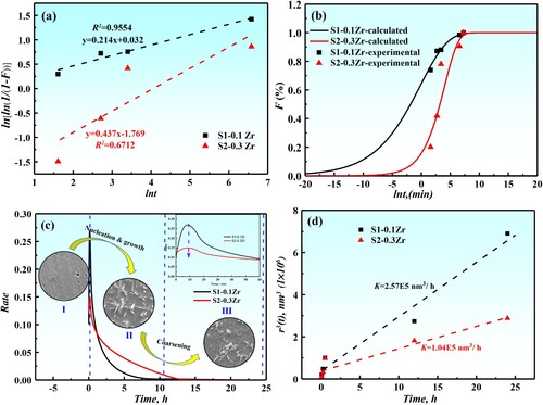
(c) shows the variation of precipitation rate at different aging time. It can be seen that the increase of Zr content significantly reduces the precipitation rate of the Laves phase. With the extension of aging time, the precipitation rate of the Laves phase particles increases first, then decreases, and gradually approaches zero. In fact, the whole process is divided into three stages. The first stage is mainly the nucleation of Laves phase particles with a large number of fine spherical precipitated particles on the matrix, as shown in (c)-I. With the extension of aging time, the particles gradually grow into short rod-shaped particles (as shown in (c)-II). After that, the particle enters the coarsening stage, which shows that the aspect ratio of the particle decreases and the particle morphology changes from short-rod to granular (as shown in (c)-III). Therefore, the precipitated phase mainly experienced a spherical needle
short-rod
granule transformation process. In fact, the morphology of precipitated particles is closely related to the particle-matrix interfacial energy, elastic strain energy and crystallographic orientation [Citation22,Citation23]. When aged for 5 min, the particle morphology in the alloy strives to keep a spherical surface to minimize the total energy, which is mainly due to the small particle size at this time, the interfacial energy dominates. During the continuous growth of precipitated particles, the large lattice misfit between BCC matrix and Laves phase will lead to the Laves phase change to short-rod shape.
In fact, the coarsening of the Lave phase belongs to the Ostwald mechanism, that is, the dissolution of small particles and then deposition on the surface of large particles. The radius of the Laves phase in the coarsening stage is obtained by the following formula [Citation24]:
(2)
(2) r is the initial particle radius. The equivalent circular particle of the same area can be defined with radius
, where l is the length of needle particle and d is the thickness [Citation25]. Thus, the relation diagram of r3 and t can be drawn, and the coarsening rate of precipitated phase of different alloys can be obtained by fitting the slope (as shown in (d)). The coarsening rate of precipitated phase are K1 = 2.57 × 10⁵ nm3/h for S1-0.1Zr, K2 = 1.04 × 10⁵ nm3/h for S2-0.3Zr, from which it can be found that the coarsening rate of precipitated phase decreases with the increase of Zr content. In fact, the coarsening is directly related to diffusion coefficient. According to relevant literature [Citation26–30], the diffusion coefficient of Zr element at 1073 K is the smallest (DTa(4.12 × 10⁻¹⁶)>DMo(2.59 × 10⁻¹⁶)>DNb(1.58 × 10⁻¹⁶)>DZr(2.26 × 10⁻¹⁸), m2/s), so the more it is added, the smaller the diffusion coefficient of solute element and the coarsening rate.
Conclusions
The influence of Zr on the precipitation behavior and mechanical properties of Fe-Cr-Al-Mo-Nb-Ta-Zr alloys has been investigated systematically. After aging, the precipitated particles of Fe-Cr-Al alloys are mainly needle Laves phase. The grain size and volume fraction of precipitated particles of Fe-Cr-Al alloys decrease with the addition of Zr element. The calculated precipitation kinetics curve of Fe-Cr-Al alloy shows a typical S-shaped curve, and the precipitation transition rate firstly increases and then decreases. With the increase of Zr content, the precipitation kinetics curve of Fe-Cr-Al alloys shifts to the right, which indicates that the incubation period of Laves phase is prolonged and the precipitation rate is slowed down. In addition, the coarsening rate of Laves phase decreases with increasing Zr content, which is related to the low diffusion coefficient of Zr element.
Disclosure statement
No potential conflict of interest was reported by the author(s).
Additional information
Funding
References
- Kim C, Kim H, Heo W, et al. High-temperature steam oxidation behavior of alumina-forming duplex FeNiCrAl and ferritic FeCrAl alloys at 800°C to 1050°C. Corros Sci. 2021;190:109658. doi:10.1016/j.corsci.2021.109658
- Sun ZQ, Edmondson PD, Yamamoto Y. Effects of Laves phase particles on recovery and recrystallization behaviors of Nb-containing FeCrAl alloys. Acta Mater. 2018;144:716–727. doi:10.1016/j.actamat.2017.11.027
- Niu B, Wang ZH, Wang Q, et al. Dual-phase synergetic precipitation in Nb/Ta/Zr co-modified Fe-Cr-Al-Mo alloy. Intermetallics. 2020;124:106848. doi:10.1016/j.intermet.2020.106848
- Zinkle SJ, Was GS. Materials challenges in nuclear energy. Acta Mater. 2013;61:735–758. doi:10.1016/j.actamat.2012.11.004
- Yuan Q, Chai LJ, Yang T, et al. Laser-clad FeCrAl/TiC composite coating on ferrite/martensitic steel: significant grain refinement and wear resistance enhancement induced by adding TiC. Surf Coat Tech. 2023;456:129272. doi:10.1016/j.surfcoat.2023.129272
- Li P, Li QQ, Jin T, et al. Effect of Re on low-cycle fatigue behaviors of Ni-based single-crystal superalloys at 900°C. Mater Sci Eng A. 2014;603:84–92. doi:10.1016/j.msea.2014.02.073
- Du JH, Lu XD, Deng Q, et al. High-temperature structure stability and mechanical properties of novel 718 superalloy. Mater Sci Eng A. 2007;452:584–591.
- Song G, Sun Z, Poplawsky JD, et al. Primary and secondary precipitates in a hierarchical-precipitate-strengthened ferritic alloy. J Alloys Compd. 2017;706:584–588. doi:10.1016/j.jallcom.2017.02.271
- Song G, Sun Z, Poplawsky JD, et al. Microstructural evolution of single Ni2TiAl or hierarchical NiAl/Ni2TiAl precipitates in Fe-Ni-Al-Cr-Ti ferritic alloys during thermal treatment for elevated-temperature applications. Acta Mater. 2017;127:1–16. doi:10.1016/j.actamat.2017.01.011
- Bahl S, Xiong LH, Allard LF, et al. Aging behavior and strengthening mechanisms of coarsening resistant metastable θ′ precipitates in an Al–Cu alloy. Mater Des. 2021;198:109378. doi:10.1016/j.matdes.2020.109378
- Yamamoto Y, Pint BA, Terrani KA, et al. Development and property evaluation of nuclear grade wrought FeCrAl fuel cladding for light water reactors. J Nucl Mater. 2015;467:703–716. doi:10.1016/j.jnucmat.2015.10.019
- Sun ZQ, Bei HB, Yamamoto Y. Microstructural control of FeCrAl alloys using Mo and Nb additions. Mater Charact. 2017;132:126–131. doi:10.1016/j.matchar.2017.08.008
- Stein F, Palm M, Sauthoff G. Structure and stability of laves phases part II – structure type variations in binary and ternary systems. Intermetallics. 2005;13:1056–1074. doi:10.1016/j.intermet.2004.11.001
- Stein F, Palm M, Sauthoff G. Structure and stability of Laves phases. Part I. Critical assessment of factors controlling Laves phase stability. Intermetallics. 2004;12:713–720. doi:10.1016/j.intermet.2004.02.010
- Sui S, Li Z, Zhong CL, et al. Laves phase tuning for enhancing high temperature mechanical property improvement in laser directed energy deposited Inconel 718. Composites Part B. 2021;215:108819. doi:10.1016/j.compositesb.2021.108819
- Stein F, Leineweber A. Laves phases: a review of their functional and structural applications and an improved fundamental understanding of stability and properties. J Mater Sci. 2021;56:5321–5427. doi:10.1007/s10853-020-05509-2
- Isik MI, Kostka A, Eggeler G. On the nucleation of Laves phase particles during high-temperature exposure and creep of tempered martensite ferritic steels. Acta Mater. 2014;81:230–240. doi:10.1016/j.actamat.2014.08.008
- Morris DG, Muñoz-Morris MA. Room and high temperature deformation behaviour of a forged Fe-15Al-5Nb alloy with a reinforcing dispersion of equiaxed Laves phase particles. Mater Sci Eng A. 2012;552:134–144. doi:10.1016/j.msea.2012.05.022
- Porter DA, Easterling K E. Phase transformations in metals and alloys. Van Nostrand Rcinhold Co; 1992. doi:10.1007/978-1-4899-3051-4_6
- Morales EV, Alvarez NJG, Leiva JV, et al. Kinetic theory of the overlapping phase transformations: case of the dilatometric method. Acta Mater. 2004;52:1083–1088. doi:10.1016/j.actamat.2003.10.041
- Morales EV, Vega-Leiva JA, Salinas HLL, et al. Analysis of precipitation mechanisms in tempering of low-alloy steels using the kinetic theory of the overlapping transformations. Phase Trans. 2011;84:179–191. doi:10.1080/01411594.2010.530031
- Voorhees PW, Johnson WC. Elastically-Induced precipitate shape transitions in coherent solids. Solid State Phenom. 1992;23-24:87–103. doi:10.4028/www.scientific.net/SSP.23-24.87
- Khachaturyan AG, Semenovskaya SV, Morris JW. Theoretical analysis of strain-induced shape changes in cubic precipitates during coarsening. Acta Metall. 1988;36:1563–1572. doi:10.1016/0001-6160(88)90224-6
- Lifshitz IM, Slyozov VV. The kinetics of precipitation from supersaturated solid solutions. J Phys Chem Solids. 1961;19:35–50. doi:10.1016/0022-3697(61)90054-3
- Galindo-Nava EI, Rainforth WM, Rivera-Díaz-Del-Castillo PEJ. Predicting microstructure and strength of maraging steels: elemental optimisation. Acta Mater. 2016;117:270–285. doi:10.1016/j.actamat.2016.07.020
- Murali D, Panigrahi BK, Valsakumar MC, et al. Diffusion of Y and Ti/Zr in bcc iron: a first principles study. J Nucl Mater. 2011;419:208–212. doi:10.1016/j.jnucmat.2011.05.018
- Perrard F, Deschamps A, Maugis P. Modelling the precipitation of NbC on dislocations in α-Fe. Acta Mater. 2007;55:1255–1266. doi:10.1016/j.actamat.2006.10.003
- Huang SY, Worthington DL, Asta M, et al. Calculation of impurity diffusivities in α-Fe using first-principles methods. Acta Mater. 2010;58:1982–1993. doi:10.1016/j.actamat.2009.11.041
- Shaikh QA. Interdiffusion measurement of niobium and tantalum in iron base alloys. Mater Sci Technol. 1990;6:1177–1180. doi:10.1179/mst.1990.6.12.1177
- Nitta H, Yamamoto T, Kanno R, et al. Diffusion of molybdenum in α-iron. Acta Mater. 2002;50:4117–4125. doi:10.1016/S1359-6454(02)00229-X