 ?Mathematical formulae have been encoded as MathML and are displayed in this HTML version using MathJax in order to improve their display. Uncheck the box to turn MathJax off. This feature requires Javascript. Click on a formula to zoom.
ABSTRACT
Coating by sol–gel deposition to modify the tribological properties of K10 carbide cutting insert was performed. The study examines the thermal and tribological characteristics of uncoated cutting inserts and the cutting inserts coated with TiO2/8YSZ and TiO2/15YSZ layers respectively. The TiO2/8YSZ and TiO2/15YSZ coatings had a hardness of 1151.6 and 1678.9 HV, respectively, and the TiO2/8YSZ and TiO2/15YSZ coated inserts had scratch hardness of 2.73 and 22.98 GPa respectively. Among the uncoated and coated inserts, the TiO2/15YSZ coated inserts had the lowest coefficient of friction and rate of wear. The TiO2/8YSZ coated insert had a lower thermal conductivity when compared to TiO2/15YSZ coated insert and uncoated carbide cutting insert (10.3 vs. 14.1, and 41.8 W/m.K). The thermal expansion coefficients of the 8YSZ layers, 15YSZ layers, and carbide cutting tool were 3.66*10−6, 3.546*10−6 and 14*10−6 K−1, respectively. The reasons for the enhancement of the tribological properties of the carbide cutting tools by the ceramic coatings are discussed.
Introduction
Ceramic coatings are layered materials with low thermal conductivity and strong thermal stability that are coated onto substrates in order to provide thermal protection in the most demanding high-temperature environment [Citation1]. In the machining processes, tool wear is a significant occurrence in any metal cutting process because it affects machining results such as machining forces, heat generation, and surface integrity of the machined surface, tool life, and overall production cost directly or indirectly [Citation2]. Additionally, many tool materials have limited thermal conductivity, which makes them unsuitable for machining. The high volume specific heat of these materials causes high cutting temperatures during machining. The selection of coating materials is constrained by fundamental properties such as phase stability, chemical inertness and high melting point. The thermal conductivity also needs to be sufficiently high to avoid high temperatures at the chip–tool interface and prevent tool material softening, which causes deformations and rapid wear. Large increases in plastic deformation are caused by high temperature, and strong adherence to metallic substrate. In essence, very few materials can fulfill these requirements. Cemented tungsten carbide (WC-Co), which is made up of large volume fractions of tungsten carbide particles in a cobalt metal matrix, is one of the most widely used tool materials in a variety of manufacturing industries, including automotive, oil and gas drilling, geothermal energy exploration, mining, construction, and other applications where extreme wear resistance is required [Citation2]. Four main properties are necessary in case of using carbide tools at high speeds. These are wear resistance, toughness (breakage resistance), durability and hot hardness (chemical stability and high hardness). Advanced coating methods have an important part and aim to raise their durability to a high level. The coating improved many properties such as toughness, fracture strength, wear resistance, thermal shock resistance and hardness. Carbide tools may have one or more thin coating films applied to them [Citation3]. Multiple layers of coatings are applied to improve the coating’s strength, protection, or other properties. The interfaces between layers can significantly alter the orientation of microcracks that form close to the top surface as they travel deeper into the coating. Multilayer coatings with various structural configurations can increase the coating’s ability to withstand the spread of cracks [Citation4]. Tools made of carbide are typically coated in one of two ways; physical vapor deposition (PVD) and chemical vapor deposition (CVD). Due of the high process temperature, the CVD technique may cause the tool’s hardness to decrease. Due to lower precipitation temperatures in the PVD technique, hardness loss has no negative effects [Citation5]. Typically, hard nitride and carbides such as TiN, CrN, TiCN, TiAlN, ZrN, TiZrN, and diamond like carbon (DLC) are used to coat carbide cutting tools. Usually, PVD techniques are used to produce such strong ceramic coatings on substrates [Citation6]. Sol gel is a chemical process that produces a highly pure, homogeneous material by mixing reagents at the atomic level. Sol-gel coatings can be applied to substrates using a variety of techniques, including spin coating, capillary coating, spray coating, flow coating, dip coating, and roll coating. Sol–gel synthesis is influenced by a number of variables, including the pH of the hydrolysis, the rate at which water is added, the gelation temperature, the gels’ aging process, the drying control chemical agents (DCCAs), and the calcination temperature. Unlike the conventional method, which uses a high temperature, the sol–gel coating method uses a low temperature. Materials produced through sol–gel synthesis have a high level of uniformity and purity when compared to alternative processes [Citation4].
Durmaza and Yildizb [Citation7] investigated the deposition of TiAlSiN, AlCrN, and TiAlN ceramic films on substrate by cathodic arc physical vapor deposition method, to enhance the wear characteristics of carbide material. The steel workpiece surface that was milled using a carbide end mill covered with a TiAlN ceramic layer had the lowest surface roughness value following a high-speed milling procedure using uncoated and coated carbide tools. Rezende et al. [Citation8] investigated the effects of multilayer cutting tool coatings on tribological situations. Cast iron was machined with tools made of K10 carbide tungsten. The tools were uncoated, multilayer coated with aluminum oxide, and coated with it (one layer of TiO2 and three layers of Al2O3). The multilayer coating fails between 30 and 40 N in a scratch test using a Rockwell indenter, while the Al2O3 coating fails at about 25 N. The multilayer coating adheres to the surface more effectively than the Al2O3 coating as a result. The complex process of choosing a coating technology is heavily influenced by the component’s capacity and financial restrictions. To properly balance the technical and financial viability of coating processes as well as the process’ compatibility with the substrate, modern design procedures take the surface into consideration from the outset. Numerous coating techniques exist, including chemical vapor deposition, physical vapor deposition, thermal spray, laser cladding, and sol–gel deposition. In contrast to traditional processes, which use high temperatures, sol–gel coating uses a moderate temperature. Sol–gel synthesis produces materials that are highly uniform and pure when compared to those made using other techniques [Citation4,Citation7,Citation8]. Wurood et al. [Citation9,Citation10] studied the best coating circumstances for ceramic oxide by sol–gel method on HSS cutting inserts, and the effect of the multilayer coated insert. They found that the tool life increased by 50%, the friction coefficient decreased by 80%, the thermal conductivity decreased by 37%, the surface roughness for the work piece decreased by 38%, and the temperature at failure decreased by 8–11%.
Few studies used the sol gel method to apply a monolayer of ceramic oxides to cutting inserts. The effect of multilayer coating on the machining performance of tools, carbide inserts, and ceramic inserts using alternative coating techniques (PVD, CVD) has also been the subject of several studies. The effect of a multilayer sol–gel coating on cutting tools (Tungsten carbide) through conventional machining has not been studied. Nanomaterial’s deposition can be an effective way to enhance the performance and lifespan of carbide cutting tools, making them more efficient and cost-effective in various industrial applications. This research aims to modify the machining capabilities of the carbide insert by improvement its tribological and thermal properties by stabilizing zirconia using the sol–gel technique.
Experimental procedure
Carbide cutting insert
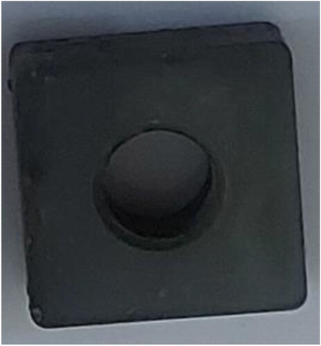
Tungsten cemented carbide inserts (K10) were used in this study. All the inserts have identical geometry designated by the American National Standard Institute (AISI) as [TNMG 160408] [Citation11]. The inserts feature a 13 mm side and a square cross section (). The utilized carbide inserts’ compositions are shown in .
Table 1. Chemical composition for carbide tool.
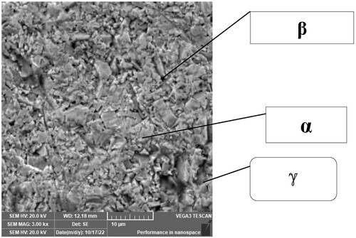
The hardness measurements were made in accordance with ASTM B294-10 standard, using a load (150 kg) HRC with a tip (120) degree and holding time of 10 s. The hardness value’s corresponding counterpart is (66.8 HRC). Following the fabrication of the cutting inserts, several emery paper grades (300, 400, 600, 800, 1000, 1500, and 2000) were used to grind the surface of the specimen to an adequate fineness, and it was then rinsed with water. The cutting insert was polished using a diamond paste with a grain size of (0.1–0.3)µm, this process continues until the sample surface becomes as mirror, and then it is washed by water and alcohol and dried by hot air. Etching process was performed by of immersion the sample for 3–6 min with freshly prepared mixture solution of K3Fe(CN)6 and sodium hydroxide then dry surfaces with acetone to indicate β (Co), α (WC) phases. To indicate ℽ (WCx) carbide of cubic lattice phase, the samples were etched in solution of K3Fe(CN)6 and sodium hydroxide about 3–4 min then washed and dried species and etched in a solution mixture of equal volumes of concentration of hydrochloric acid and water about 10 s, re etched about 20 s in the first mixture [Citation10,Citation12]. Then used Scanning Electron Microscope, the SEM morphology of the uncoated sample implant is depicted in .
Preparing the coating materials (TiO2/Zr2O3+Y2O3) by sol–gel route
The surfaces of the cutting insert specimen were prepared by ordinary grinding starting at grade 220 and gradually increasing to grade 600. Grinding was done to ensure uniform roughness across all of the specimen surfaces. Before being dried in the air, the cutting inserts were first cleaned in an ultrasonic acetone bath for 15 min and then in methanol for 10 min. The built insert specimen received two distinct coating layers. These sorts consist of: titania TiO2 and yttria stabilized zirconia YSZ.
Titanium tetra-isopropoxide (TTIP) was used in the preparation of the Ti(OH)4 precursor together with 0.7N-hydrochloric acid (HCl) as a catalyst and isopropanol IP as a solvent. The typical composition had a molar ratio of TTIP: IP: 0.7NHCl = 1:26.5; 1.5. The mixture was stirred constantly for an additional hour at room temperature at 50 rpm. For the created Ti(OH)4 precursor’s PH was tested and found to be 5.83. By dip coating, each cutting insert specimen is immersed in a titanium hydroxide solution after 3 s of immersion time, at 10 cm/min speed, and after an hour of drying at 335°C.
To make YSZ, an initial solution was zirconium n-propoxide (ZNP), ethanol, and HNO3. The mixture was continually swirled while being ultrasonically sonicated in an ice bath (100 rpm). Then distilled water and acetic acid were added in a 3:1 weight ratio after 30 min. The molar ratios for ethanol, isopropanol, and water in these solutions were 10: 1, 6.6: 1, and 7: 1, respectively. Using 21.29 g of Yttrium (III) tris isopropoxide, 4.8 ml of isopropanol, and 5 ml of HNO3, a second solution was prepared by mixing. The solution was kept stirred for 15 min at 100 rpm to produce an 8 mol% of Y2O 8YSZ. Similar solutions were prepared, but this time the amount of Yttrium (III) tris isopropoxide was changed to produce a 15% mol of Y2O3 (15YSZ). After obtaining a pH of 4.43 of this solution, sample of titania coated was submerged in this solution (Y(OH)3 and Zr(OH)4) for 7 min. The samples were first dried in the air for 48 h at ambient temperature, then calcinated for three hours at 700°C with a rate of 3°C/min.
Characterization and testing
The morphology and coating layer thickness were investigated using field emission scanning electron microscopy. XRD analyses were used to determine the crystal phase, a scan range of (20–80) degrees, and a scan speed of (3 degrees per minute).
This friction and wear tests were conducted using the pin-on-disc method according to the ASTMG9 standard. A steel disc rotating at 300 rpm with the sample coated and uncoated fastened on it, a load of 10 N, and a sliding distance of 226.08 m were used in the experiment, for duration of the test 30 min. The pin was a ball pressed up against the whirling disc. A martensitic steel ball (pin) with a hardness of (990 HV) was used to conduct wear testing on the coated and uncoated cutting inserts. Weighing the specimens by a sensitive scale with an accuracy of before and after the test to calculate the weight loss was done. The wear rate of the specimen is calculated according to the following equation 1 [Citation13]:
(1)
(1) where: R.W: rate of wear (g/m); ΔW: weight lost (g).; t: time (min.).; r: The radius of the sample to the center of the disc (4 mm); n: the speed of disk (300 rev/min).
Indenter of silicon carbide was utilized to analyze the movement of the indenter along the coated, examined specimen’s surface in the scratch test. To examine the coating’s adherence to the insert, the test was run with a steadily increasing force. The following parameters were employed in the testing, which were conducted in accordance with ASTM D4541: With a load range of 5–50N, the penetrator travels over a distance of 4 mm at a speed of 1 mm/s [Citation14].
Rockwell hardness tester uncoated carbide cutting insert was conducted using a load of (150 kg) with a tip of (120)degree at 10s. The load and displacement of the tip were recorded on the region of contact between the tip and the sample during an indent. Using a load of (500 g), the Vickers hardness test for the carbide coated has been evaluated for (10 s).
The Hot Disk Thermal Constants Analyzer is a tool for transient plane source (TPS) thermal characterization. The Hot Disk sensor was a heat source and a dynamic temperature sensor. An electrical current utilized for the measurement heated the sensor, which was then used to track the temperature rise over time. The experiment was performed on the Swedish-manufactured Hot-Disk TPS 500 model.2.8. The coefficient of thermal expansion (CTE) is a measure of how much a material will expand or contract in response to changes in temperature. To measure the coefficient of thermal expansion, a dilatometer was used to measure how the substance’s dimensions change in proportion to temperature. The sample is 13 mm long with a cross-sectional diameter of 2.5 mm.
Results and discussion
Characterization of the coating layers
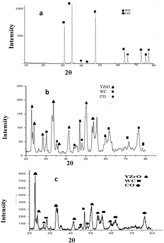
The carbide cutting insert, 8YSZ, 15YSZ layer were identified using X-ray diffraction (XRD) analysis at a rate of 3 degrees per minute. In comparison with the diffraction data cards (25-1047), (05-0727), the results for the WC and Co peaks were shown in (a). (b) depicts the 8YSZ layer’s XRD. In order to compare the 8YSZ XRD pattern to the diffraction data card (00-082-1246), which displays six peaks of the Y0.2 Zr 0.8 O 1.9 phase and agrees with Artras ALGA et al. [Citation14]. According to (c), the Y0.2 Zr0.8 O1.9 phase’s intensity increased with the addition of the 15YSZ layer. A shafted addition could be seen in the beak because the diameter ions for Yttrium were equal to (1.04) Å and were larger than the radius ions for zirconium (0.74) Å, so the rise in Yttrium percentage caused the shaft to move to the left side. The stabilization of the cubic phase in sol–gel YSZ coating depends on temperature, heat treatment, and yttria concentration [Citation15]. (b) depicts the 8YSZ layer’s XRD. In order to compare the 8YSZ XRD pattern to the diffraction data card (00-082-1246), which displays six peaks of the Y0.2 Zr 0.8 O 1.9 phase and agrees with Artras ALGA et al. [Citation14]. According to Francisco et al. [Citation15], the stabilization of the cubic phase in sol–gel YSZ coating depends on temperature, heat treatment, and yttria concentration [Citation16,Citation17].
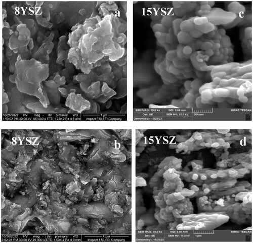
By varying the quantity of Yttrium oxide, YSZ thin films were produced, and the surface morphology was examined using field scanning electron microscopy. The representative FESEM micrographs of YSZ thin film prepared by 8YSZ and 15YSZ are shown in (a)–(d). For better understanding of the crystal growth process of the YSZ layers and quantitative description of the surface morphology, addition the influence of yttria concentration on the morphology of the end products. The crystallite size decreased as the molar concentration of yttria increased from 8 to 15%; this indicates that the yttria content rise impeded crystal formation. This characteristic has been linked to the segregation of yttria at grain borders, which reduces mass transfer by surface diffusion and prevents the development of crystals that are consistent with [Citation15].
Figure 4. FESEM image of a multilayer coating (YSZ) on carbide insert: (a) 8YSZ 100000 Mag., (b) 8YSZ 25000 Mag., (c) 15YSZ 100000 Mag., (d) 15YSZ 25000 Mag.
depicts a comparison between the morphology of 8YSZ layer and a like layer prepared by electrostatic spray on the carbide insert (Pavandatta M Jadhav et al.) [Citation18]. Can be noticed less agglomeration in particles through sol -gel method deposition, as shown (a), while more segregation can be found in (b) [Citation18].
Figure 5. (a) FESEM image of coating 8YSZ on carbide insert by Sol_ gel, (b) FESEM image of 8YSZ thin film on carbide insert by Electrostatic Spray coating [Citation18].
![Figure 5. (a) FESEM image of coating 8YSZ on carbide insert by Sol_ gel, (b) FESEM image of 8YSZ thin film on carbide insert by Electrostatic Spray coating [Citation18].](/cms/asset/ca62ca81-2ff2-4a1a-9572-7b75c9761775/thts_a_2331865_f0005_ob.jpg)
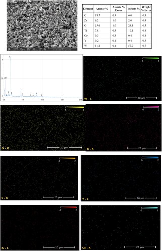
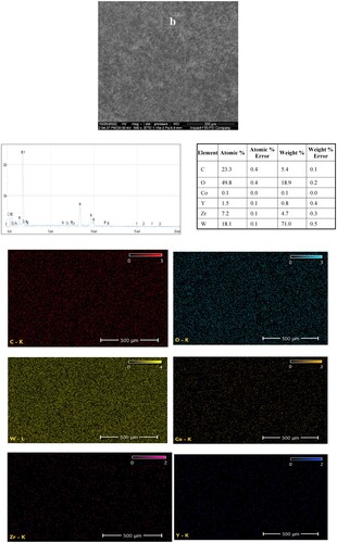
EDS mapping was carried out for the coatings TiO2/8YSZ layers and 15YSZ layer. (a), which depicts the spread of Ti, Zr, Y, O, W, and CO elements in region, summarizes the findings. These findings support the direct deposition of TiO2 on the substrate in the region of the titania layer, and the regions of Zr, Y, and O show the deposition of the Y Zr O phase. While using 15% yttria in stabilized zirconia can be shown in (b), the amount of yttria is growing.
Figure 6. EDS mapping of prepared sample: (a) TiO2 /8YSZ top coated insert, (b) 15YSZ top coated insert.
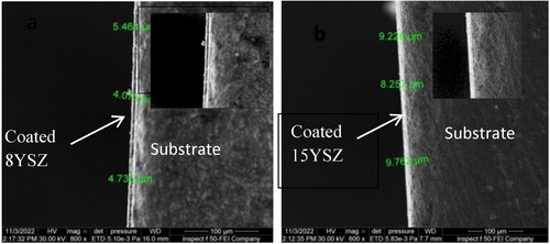
(a) and 7(b) describe the effect of the amount of yttria added to the hydroxide solution Zr(OH)4 mixture on the thickness of the coated layer. When the amount of yttria added was increased from 8% to 15% mol during the same 10-second immersion period for the carbide sample in the coated solution, the layer thickness increased. This has to do with the size of Yttrium ions and how those ions’ size particles differ from those of zirconium ions. The radius of zirconium ions 0.74 Å while the ionic raduis of yttirum 1.02 Å.
Physical tests
Thermal expansion coefficient
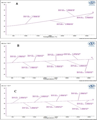
The bulk carbide insert thermal expansion coefficient is (14 *10−6 1/K) as shown as (a), The results confirm earlier research that the Co content has a significant impact on the CTE of WC-Co composites but that the coefficient is not unduly sensitive to variations in WC grain size. This incidence is probably being caused by Cobalt’s higher CTE than WC’s [Citation2]. When the amount of yttria increased from 8 to 15%mol, according to [Citation19], the material’s thermal properties changed. As a result, thermal conductivity increased and thermal expansion was reduced. This means that the thermal properties of zirconia in high-temperature applications are diminished as the yttria fraction is raised. Cutting tool ceramic coatings with 8YSZ and 15YSZ exhibit (3.66*10−6 and 3.546*10−6 1/K) thermal expansion, respectively that agree with Cao et al. [Citation19].
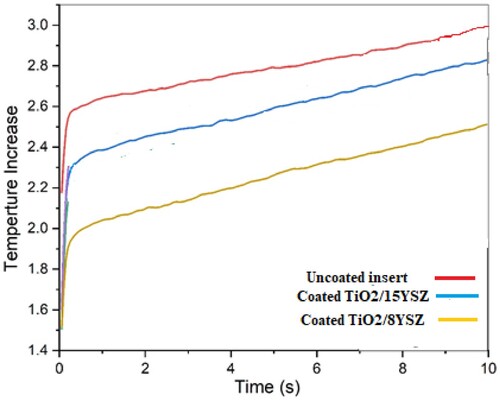
The thermal conductivity of the carbide insert used in this work is equal to (41.8 W/m.K), which is consistent with earlier research by Zhang et al. [Citation20]. Both the WC particle size and the cobalt content have a substantial impact on the thermal conductivity of WC-Co materials. In general, cobalt content and WC particle size can affect thermal conductivity [Citation19]. Utilizing a transient plane source (TPS), the thermal conductivity of the ceramic coatings was measured. Typically, the bulk carbide insert heat conductivity is much higher than that of the ceramic coating. YSZ has a high thermal expansion coefficient, thermal shock resistance, and low thermal conductivity that affects the weight percentage of Y2O3 in the coated layer. The coated layer (TiO2/8YSZ) has the lowest thermal conductivity measured at 27°C at room temperature (10.3W/m.k), while the TiO2/15YSZ coating layer’s thermal conductivity at room temperature was(14.1 W/m. K), shows The nanostructured Yttria-Stabilized Zirconia (8 mol% Y2O3) 8YSZ was determined to be the most promising TBC for a variety of fundamental needs. Because it offers superior capabilities in high temperature applications, Yttria-Stabilized Zirconia (YSZ) nanostructured coatings provide thermal barrier coating TBC materials [Citation2].
Hardness and wear properties
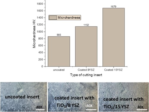
As shown in , microhardness of the uncoated carbide insert is 866 HV, and with 8YSZ and 15YSZ coatings, it increases to 1152 and 1679 HV, respectively. The images of the indents produced by indentation in clearly illustrate that the hardness of the surface increase signficantly with every deposit, reaching twice the hardness, of carbide cutting tool with 15YSZ coating. These results are in agreement with those reported in reference [Citation14].
Figure 10. The micro hardness of uncoated insert and different coatings, and the images of indents produced on the surface of uncoated inserts and different coatings. (Please put the sizes corresponding to the scale bars on the images).
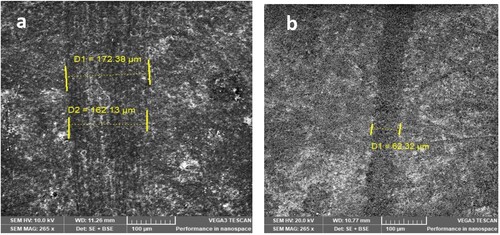
In comparison to the TiO2/15YSZ coating, which fails at 35 N and has a line of scratch width of 62.32 µm, the TiO2/8YSZ coating fails in the scratch test at roughly 30 N. Francisco J et al. [Citation15] discovered that compared to the 8YSZ coating, the 15YSZ coating (with a higher yttria concentration) appeared to have greater adherence. shows the scratch width for 8YSZ and 15YSZ coatings. The normal force at the time of coating detachment must be multiplied by the values of the scratch hardness to produce the critical load in order to create a coating adhesion value that is comparable. shows scratch-resistant comparison between 8YSZ/15YSZ layers.
Table 2. Mechanical qualities of the coating.
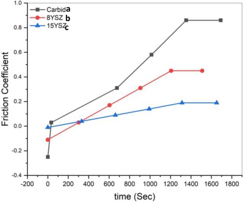
(a)–(c) displays the behavior of the coefficient of friction for an uncoated and multilayer coated cutting insert (TiO2/YSZ) versus time. The initial friction coefficients of the uncoated carbide was (0.71) while the friction coefficient of carbide coated TiO2/8YSZ (0.31), and (0.17) with coated insert TiO2/15YSZ, which are greatly lower than those provided for uncoated carbide. This variation is related to the ceramic coatings’ superior chemical inertness and lower heat conductivity. Pavandatta M. Jadhav et al. description’s of the effect of YSZ nano coating on the tungsten carbide tool material is the main focus of this investigation [Citation18].
Figure 12. Coefficient of friction versus time of uncoated insert and the inserts coated by TiO2/8YSZ and TiO2/15YSZ coatings respectively.
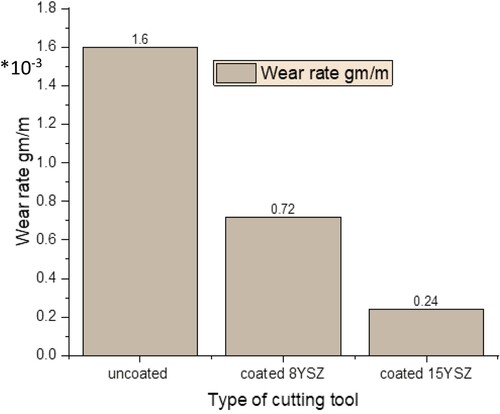
Tribological tests were conducted in two scenarios to evaluate the efficacy of dry sliding (Coated and Uncoated). The wear rate is measured in this investigation. Under a SEM microscope, the worn uncoated insert surfaces were examined to check for variations in wear behavior brought on by the presence of the TiO2/8YSZ nanoparticles. Severe wear evidenced by top surface disintegration, wear debris, and deep grooves in the sliding direction were the principal characteristics of an uncoated disc’s worn surface. (a) and 13(b) displays a deep and wide wear track, a surface roughness and mass change graph. Less affected sample under the same wear conditions with coated insert TiO2/15 YSZ from (c) that related with the amount of yttria to increase wear resistance.
Figure 13. Wear track SEM micrographs of (a): uncoated inserts, (b): coated insert (8 YSZ), (c):coated insert (15 YSZ).
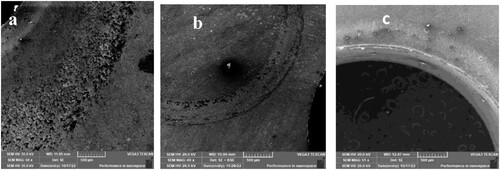
The presence of ceramic material, which protects the contact surface from wear loss and to some extent resists plastic deformation, may be the cause of this. In contrast to YSZ coated insert, high adhesion and extensive plastic deformation between the opposing surfaces during sliding motion causes the change in mass induced by the same rotating speed to result in severe scratches on the contact surface [Citation18].
Our findings demonstrate that the wear rate for carbide cutting tools, TiO2/8YSZ and TiO2/15YSZ, respectively, 1.6 *10−3, 0.72 *10−3 and 0.24*10−3 g/m. These values are comparable to those that have been reported for YSZ coated carbide cutting tool plasma sprayed [Citation18]. The wear rate of an uncoated insert is at its highest in , but as the insert becomes YSZ coated, the wear rate is significantly decreased and continues to decline. Since coated inserts with TiO2/8YSZ and TiO2/15YSZ have higher ceramic layer hardness and better adherence to substrates than uncoated inserts, they essentially experience less wear.
Conclusions
According to the experimental findings, the length of immersion and the quantity of yttria had an impact on the coating layer’s thickness, particle size, homogeneity, physical and tribological properties when the carbide cutting tool was coated using the sol–gel method.
When the amount of yttria added was increased from 8% to 15% mol, the layer thickness grew from (4.5 into 9) µm. The crystallite size decreased and an aggregation could be noticed as yttria’s molar content rose from 8 to 15%.
Titania is a reduction in the differences in physical properties between the ceramic layer (YSZ) and the substrate, since the average TEC of the titania layer and the carbide insert (11, 14* 10−6 1/K) are nearly comparable.
The TiO2/15YSZ layer on the substrate displayed a lower coefficient of friction and wear rate in comparison to TiO2/8YSZ. Additionally, its hardness and scratch resistance were higher than TiO2/8YSZ. In spite of TiO2/8YSZ, had excellent thermal properties comparing TiO2/15YSZ.
Disclosure statement
Ministry of Industry and Minerals State Company for Automotive.
Additional information
Funding
References
- Xu RG, Chen Z, Chen P, et al. Mechanical properties of advanced multifunctional coatings. Coatings. 2022;12(5):599. doi: 10.3390/coatings12050599
- Wang H, Webb T, Bitler JW. Study of thermal expansion and thermal conductivity of cemented WC–Co composite. Int J Refract Met Hard Mater. 2015;49:170–177. doi: 10.1016/j.ijrmhm.2014.06.009
- Suresh R, Basavarajappa S, Gaitonde VN, et al. Machinability investigations on hardened AISI 4340 steel using coated carbide insert. Int J Refract Met Hard Mater. 2012;33:75–86. doi: 10.1016/j.ijrmhm.2012.02.019
- Asaad M W, Al-Ethari H, Kareem SJ. Surface modification of cutting tool by multilayer coatings a-review paper. In: AIP Conference Proceedings, Dohuk University, Iraq. AIP Publishing; 2022. p. 1–10.
- Bennett A. Properties of thermal barrier coatings. Mater Sci Technol. 1986;2(3):257–261. doi: 10.1179/mst.1986.2.3.257
- Ronghua W, John JV, Jesse NM, et al. Aspects of plasma-enhanced magnetron-sputtered deposition of hard coatings on cutting tools. Surf Coat Technol. 2002;158–159:465–472.
- Durmaz YM, Yildiz F. The wear performance of carbide tools coated with TiAlSiN, AlCrN and TiAlN ceramic films in intelligent machining process. Ceram Int. 2019;45(3):3839–3848. doi: 10.1016/j.ceramint.2018.11.055
- Rezende BA, Santos AJd, Camara MA, et al. Characterization of ceramics coatings processed by sol-gel for cutting tools. Coatings. 2019;9:755. doi: 10.3390/coatings9110755
- Asaad W, Al-Ethari H, Kareem S. Investigation of microstructure, morphology and properties of monolayer and multilayer coating T6-HSS by the sol–gel route. Adv Mater Process Technol. 2023;9(4):1594–1620. doi: 10.1080/2374068X.2022.2129518
- Asaad W, Al-Ethari H, Kareem SJ. Using grey relation analysis to improve tool life in medium carbon steel turning by coating multilayer HSS insert. In: 2022 13th International Conference on Mechanical and Aerospace Engineering (ICMAE), Bratislava. IEEE; 2022 July. p. 507–513.
- ASTM handbook, iron and metal products, 1989, Vol. 01.01.
- Gill SS, Singh J, Singh H, et al. Metallurgical and mechanical characteristics of cryogenically treated tungsten carbide (WC–Co). Int J Adv Manuf Technol. 2012;58:119–131. doi: 10.1007/s00170-011-3369-4
- Hammood SA, Al-Ethari H, Al-Juboori HAH. Effect of cement kiln dust on properties of Al-base composite prepared by P/M. In: 2017 8th International Conference on Mechanical and Aerospace Engineering (ICMAE). IEEE; 2017 July. p. 204–208.
- Žalga A, Abakevičienė B, Žarkov A, et al. On the properties of yttria-stabilized zirconia thin films prepared by sol-gel method. Mater Sci. 2011;17(2):191–196.
- Cano FJ, Castilleja-Escobedo O, Espinoza-Pérez LJ, et al. Effect of deposition conditions on phase content and mechanical properties of yttria-stabilized zirconia thin films deposited by Sol-Gel/Dip-coating. J Nanomater. 2021;2021.
- Chen AN, Lu L, Cheng LJ, et al. TEM analysis and mechanical strengthening mechanism of MnO2 sintering aid in selective laser sintered porous mullites. J Alloys Compd. 2019;809:151809. doi: 10.1016/j.jallcom.2019.151809
- Chen AN, Gao F, Li M, et al. Mullite ceramic foams with controlled pore structures and low thermal conductivity prepared by SLS using core-shell structured polyamide12/FAHSs composites. Ceram Int. 2019;45(12):15538–15546. doi: 10.1016/j.ceramint.2019.05.059
- Jadhav PM, Kumar Reddy NS. Wear behavior of carbide tool coated with yttria-stabilized zirconia nano particles. In: IOP Conference Series: Materials Science and Engineering. IOP Publishing; 2018 April. Vol. 346, p. 012007.
- Cao XQ, Vassen R, Stöver D. Ceramic materials for thermal barrier coatings. J Eur Ceram Soc. 2004;24(1):1–10. doi: 10.1016/S0955-2219(03)00129-8
- Zhang S, Liu Z. An analytical model for transient temperature distributions in coated carbide cutting tools. Int Commun Heat Mass Transfer. 2008;35(10):1311–1315. doi: 10.1016/j.icheatmasstransfer.2008.08.001


