
 ?Mathematical formulae have been encoded as MathML and are displayed in this HTML version using MathJax in order to improve their display. Uncheck the box to turn MathJax off. This feature requires Javascript. Click on a formula to zoom.
ABSTRACT
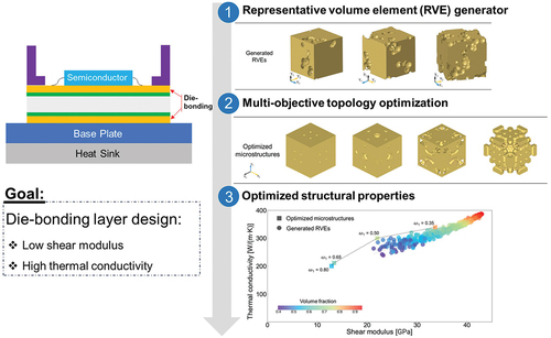
To enhance semiconductor efficiency, it is imperative to develop a die-bonding material possessing exceptional thermal conductivity and stress-shielding capabilities to safeguard semiconductor components from detrimental heat and destructive stress. In this study, we employed a multi-objective topology optimization approach to design a porous microstructure for the die-bonding layer of semiconductors, targeting high thermal conductivity and low shear modulus. The finite element analysis method for a representative volume element (RVE) facilitates computational evaluations of macroscopic mechanical and thermal properties arepsilong from a periodic microstructure. Our investigation commenced with the creation of an RVE generator for obtaining periodic microstructures featuring randomly distributed pores with controlled morphological features. A high-throughput evaluation of numerous generated microstructures explored the impact of volume fraction and pore connectivity on macroscopic shear modulus and thermal conductivity. Despite the high-throughput evaluation indicating that pore connectivity has minimal effect on properties, the multi-objective topology optimization, addressing the conflict between maximizing thermal conductivity and minimizing shear modulus, revealed that connected pores and dispersed distribution in the architected microstructure contribute to improved material performance. In this optimization process, we employed a weighted sum method to find optimal compromised microstructures. Anisotropic and orthotropic microstructures were designed, and the effects of volume constrains and weight factors on microscopic morphology were explored. Despite the high-throughput evaluation suggesting a limited impact of pore connectivity, the results from multi-objective topology optimization underscored the significance of connected pores and dispersed distribution in achieving superior material performance.
GRAPHICAL ABSTRACT
IMPACT STATEMENT
Investigated the impact of microscopic morphology on material performance in die-bonding layer of a semiconductor.
Design of optimal microscopic morphology using computer-oriented design approach.
Proposed multi-objective topology optimization to design periodic porous microstructure.
Compared architected microstructure designed by topology optimization with microstructure containing randomly distributed pores.
1. Introduction
Die-bonding materials, an important part of a power module, attach the semiconductor die to its package or substrate. A die-bonding material with outstanding thermal conductivity, such as copper, can facilitate the removal of the heat generated from semiconductor components. Additionally, an excellent stress-shielding ability is required for the die-bonding material to avoid transmitting destructive stresses to the semiconductor components; easily deformed porous microstructures consisting of interconnected pores or channels have been introduced to aid this process. Recently, experimental investigations on the characterization and fabrication of porous microstructure have been widely reported [Citation1,Citation2]. Owing to the time and cost requirements, performing straightforward experimental measurements on numerous porous materials with different volume fractions, pore connectivity, and morphologies is barely feasible. In this context, computational analysis and the design of porous microstructures [Citation3–5] have emerged as promepsilong approaches.
Topology optimization, a sophisticated design approach for structures, has been applied in various research fields, including compliant mechanisms [Citation6,Citation7], fluid flow devices [Citation8,Citation9], and actuators [Citation10,Citation11]. The density-based topology optimization method proposed by Bendsøe [Citation12] enables the wide adoption of the conventional solid-void material interpolation scheme in commercial engineering software, such as Altair OptiStruct (Altair Engineering Inc., U.S.A.) and OPTISHAPE-TS (Quint Co., Japan). In addition, level-set-based topology optimization has also been proposed [Citation13–16] and shown to be successful in both structural designs for macrostructures [Citation17–19] and microstructures [Citation20,Citation21]. Previous studies have computationally designed microstructures to improve single-objective performance by using topology optimization [Citation22–27]. For instance, materials with negative Poisson’s ratios [Citation28,Citation29] and extremal thermal conductivities [Citation30] have been reported. Although the designed microstructure has a complex morphology, designs with customized mechanical properties can be effectively fabricated using three-dimensional printing [Citation31]. Nevertheless, the advancement in single-objective performance design fails to seek a compromise between two conflicting performances of die-bonding materials. In die-bonding material design, a porous microstructure with a reduced shear modulus favors stress-shielding capability but is detrimental to thermal conductivity. Considering the conflicting objective between the shear modulus minimization and thermal conductivity maximization of a porous microstructure [Citation32], multi-objective topology optimization is required to achieve an optimal design with compromised properties for semiconductor die-bonding materials.
Previous studies have successfully applied different multi-objective optimization techniques to solve real-world macrostructure design problems [Citation33–36], and more recently, microstructure design problems [Citation37,Citation38]. A representative volume element (RVE) is the smallest periodic unit of a material that enables efficient evaluation of the macroscopic properties, such as the shear modulus, conductivity, and permeability of the entire structure [Citation39,Citation40]. Topology optimization has been incorporated with numerical homogenization to obtain multi-objective designs of RVE to tailor the desired macroscopic properties [Citation41–43]. For instance, a multi-objective topology optimization method has been developed to design a periodic microstructure considering thermo-mechanical coupling [Citation44] and multifunctional metamaterials with tunable thermal expansion and phononic bandgap [Citation45]. Additionally, Alacoque et al. [Citation46] used topology optimization methods to generate multiphase materials with periodic microstructures, which simultaneously achieved a high stiffness and a negative thermal expansion coefficient. These studies demonstrated the applicability of topology optimization in multi-physics design problems. However, the application of multi-objective topology optimization in the design of semiconductor die-bonding materials has not yet been reported.
In this study, we employed a computer-oriented design approach based on finite element analysis for a periodic microstructure, to design a porous microstructure in the die-bonding layer of semiconductors. Boundary value problems for both mechanical and thermal aspects were addressed through solution methods. Initially, the morphological impact of the microstructure on macroscopic material performance was examined via a high-throughput evaluation, wherein a generator of microstructures with varying morphological features was developed to investigate the relationships between microscopic morphology and macroscopic properties by using finite element analysis. Next, microstructures having optimized morphology were calculated using multi-objective topology optimization, wherein the objective function was defined with weighted sum of two objective functions based on macroscopic strain and temperature gradient modes. Weight factors and constraint conditions for controlling the compromised optimization outcomes were explored. Finally, to showcase the effectiveness of the multi-objective optimization, the performance of the architected microstructures was compared with that of the generated microstructures containing randomly distributed pores.
2. Finite element analysis for periodic microstructure
Utilizing the finite element analysis method for periodic microstructure enables the characterization of macroscopic material properties while considering the intricate geometry of a microstructure. The formulation of boundary value problem is based on a mathematical homogenization method [Citation47,Citation48], wherein the macroscopic boundary value problem is conceptualized solely as a constitutive relationship [Citation49,Citation50]. In this study, this method was applied to assess macroscopic shear modulus and thermal conductivity.
2.1. Boundary value problem for the mechanical problem
Boundary value problem for a periodic microstructure is formulated as follows:
where denotes the micro-scale coordination;
indicates the differential volume of the periodic microstructure;
represents the Sobolev space of periodic functions;
and
denote the periodic displacement and its variation, respectively; and
indicates the Cauchy stress. The displacement field
of the micro-scale is defined as follows:
where denotes the macroscopic strain. The microscopic strain
can be formulated as
In this formulation, a periodic microstructure lacks a defined scale; in other words, the length at the micro-scale is unspecified. Considering point on one side of the face and its mapping point
on the opposite face, the displacement difference between the two points is satisfied using the following equation:
The macroscopic stress is defined by the volume average of stress at micro-scale in the following manner:
Utilizing EquationEquations (4)(4)
(4) and (Equation5
(5)
(5) ), the components of the macroscopic stress
or strain
were controlled to solve the boundary value problem expressed by EquationEquation (1)
(1)
(1) using finite element method.
2.2. Boundary value problem for the thermal problem
The thermal equilibrium can be formulated as
where denotes the heat flux, and
represents the functional space similar to
.
is the temperature field at the micro-scale, which is defined as follows:
where, is the temperature basis, and
is the temperature difference from the temperature basis.
where indicates the temperature gradient associated with the macro-scale, and
represents a fluctuating part originating from the heterogeneities at the micro-cale. The temperature gradient at the micro-scale
can be obtained as
Based on the periodic boundary condition, the microscopic problem can be solved by governing the temperature gradient at the macro-scale, as follows: Considering point on one side of the face and its mapping point
on the opposite face, the following equation similar to Equation (4) is obtained:
The heat flux at macro-scale is calculated using the volume average of the heat flux at micro-scale
as
Using EquationEquations (10)(10)
(10) and (Equation11
(11)
(11) ), components of the macroscopic temperature gradient
or heat flux
were controlled to solve the boundary value problem expressed by EquationEquation (6)
(6)
(6) using finite element method.
3. High-throughput evaluation of microstructure effect
The finite element analysis for a periodic microstructure efficiently characterizes the impact of microscopic morphology on macroscopic material properties. Coupled with a microstructure generation algorithm encompassing varied morphological features, a high-throughput system was established to assess the relationship between microscopic heterogeneity and macroscopic material performance.
3.1. RVE generator
To perform high-throughput evaluation based on finite element analyses, RVEs of the porous microstructure, characterized by the pore connectivity and pore volume fraction, were randomly generated by inserting pores with various radii using Boolean subtraction in a periodic cube design space. The pore connectivity was defined as
where denotes the number of connected pores, and
indicates the total number of pores. The pore fraction is represented as the volume fraction, which refers to the proportion of the solid part of the model. The volume fraction of the solid part is defined as follows:
where and
denote the volumes of the solid part and the entire cube, respectively.
To control pore connectivity, we first created an abundance of connected pores and then randomly generated separated pores. Here, we began by randomly generating a seed point near the surface, as shown in . The radius of the first pore was defined to ensure that it intersected the
surface. Random increments were then introduced along the
,
, and
axes to determine the position of the second seed point, with the radius ranging from the previous pore radius to the maximum possible value. The newly created pore radius was defined to ensure that this pore intersected the previous pore, and this process was repeated until the seed point was outside the cube. The distribution of the seed points is shown in , and the creation of the connected pores is illustrated in . After generating the connected pores, we randomly created several additional pores in areas that were not in contact with the interconnected pores, as depicted in , to control the pore connectivity. To ensure that the resulting porous microstructure did not exhibit extreme anisotropy, seed points were required to grow in the dendritic branches. When a seed point triggered the growth of dendritic branches, a branch of connected pores was produced, which tended to avoid generation along the
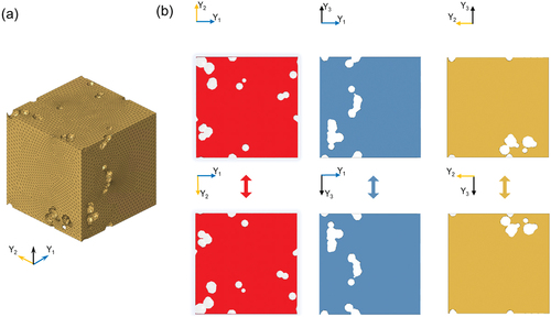
-direction. shows the generation of a trunk path of connected pores, illustrates the growth of a branch from the trunk, and depicts the growth of a sub-branch from the first branch. Also, to ensure that the RVEs were periodic, the pores in contact with the side of the cube were copied to the opposite side. Each pore was individually copied and pasted onto the opposite side of the face to ensure periodicity. An example of a randomly generated RVE is shown in , and symmetrical pore distributions on one side and its opposite side are illustrated in , confirming the successful establishment of the RVE generator.
Figure 1. Process of constructing representative volume elements. (a) Generation of the first seed on the surface of = 0. (b) Generation of abundant seeds. (c) Radius distribution of seeds to obtain interconnected pores. (d) Random generation of separated pores.
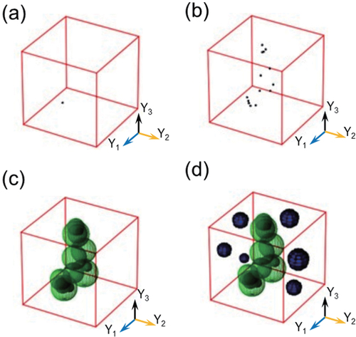
Figure 2. Control of pore connectivity and anisotropy in porous microstructures.
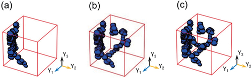
Figure 3. (a) Generated representative volume element. (b) Geometric periodicity on one side face and the corresponding opposite face of the cube.
3.2. High-throughput evaluation
In this study, a total of 332 RVEs with different pore connectivities and volume fractions were generated using the RVE generator. On the basis of the mechanical and thermal problems outlined in Section 2, we conducted finite element analyses on 332 RVEs to assess the macroscopic shear modulus and thermal conductivity. Finite element meshes were created using automated meshing function of Altair HyperWorks (version 2020, Altair Engineering, Inc., U.S.A.) utilizing four-node tetrahedral elements, in which the mesh resolution is defined as enough fine to reproduce the generated geometry and reduce numerical discretization error as shown in . To set up periodic boundary conditions, the surface nodes on the opposite sides were generated as the same arrangement.
3.2.1. Effects of microstructure on shear modulus
To assess the macroscopic shear modulus, finite element analysis was performed by imposing the prescribed macroscopic strain for pure shear to an RVE:
Macroscopic shear modulus can be calculated as follows:
In finite element analysis, the generalized Hooke’s law was employed for the constitutive model of the solid part, wherein the stress at the reference configuration can be defined as
where represents the fourth-order elastic tensor. Copper was considered as the constitutive material, with a Young’s modulus of 120 GPa and Poisson’s ratio of 0.35.
We conducted a high-throughput evaluation to obtain the shear modulus distribution of the RVEs with different pore connectivities and volume fractions (). The different colored dots in the figure represent the shear modulus values of the RVEs. Our analysis showed that the shear modulus increased with an increasing volume fraction, indicating a strong positive correlation between the two. We displayed different structures with the similar volume fraction of
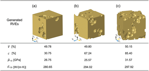
50% but different pore connectivities as an illustrative example (). Microstructure with pore connectivities of
,
, and
had shear modulus values of 26.75, 25.57, and 31.57 GPa, respectively. Despite the significant difference in pore connectivity, we observed no significant proportional relationship between shear modulus and pore connectivity. This result suggests that the dominant factor controlling the shear modulus was the volume fraction in such microstructures containing randomly distributed pores.
Figure 4. Shear modulus of the generated representative volume elements using high-throughput evaluation.
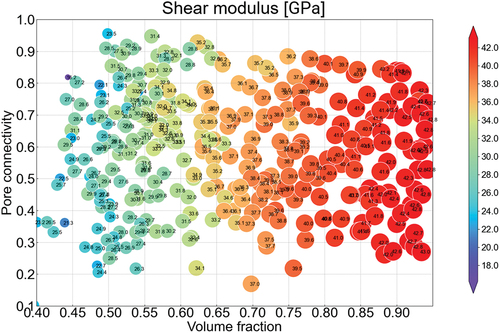
Figure 5. Representative volume elements (RVEs) with identical volume fractions (
50%) but different pore connectivity.
3.2.2. Effects of microstructure on thermal conductivity
For the assessment of macroscopic thermal conductivity, finite element analysis was performed by applying the designated macroscopic temperature gradient to each RVE:
Macroscopic thermal conductivity along the -direction of a periodic microstructure was calculated using the following equation:
where and
and denotes the macroscopic heat flux and temperature gradient in the
-direction. In finite element analysis, the matrix material is considered as copper, with a thermal conductivity of 397
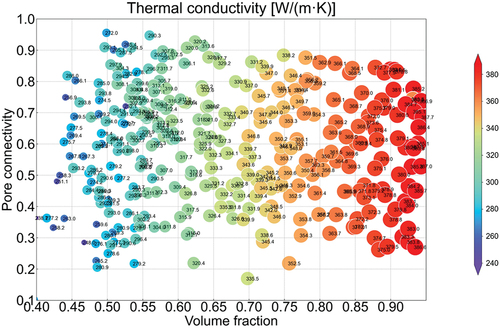
. illustrates the distribution of the thermal conductivity in the RVEs with varying pore connectivities and volume fractions obtained through the high-throughput evaluation. The dots in the figure represent the thermal conductivities of RVEs. The analyses indicated that the thermal conductivity of the RVEs increased with an increase in the volume fraction, which means a positive correlation between thermal conductivity and volume fraction. Additionally, no significant relationship was observed between thermal conductivity and pore connectivity. This result indicates that the dominant microstructure feature controlling the thermal conductivity is the volume fraction same as the macroscopic shear modulus.
Figure 6. Thermal conductivity of generated representative volume elements using high-throughput evaluation.
4. Multi-objective topology optimization
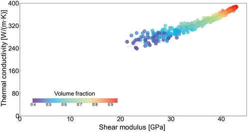
The outcomes of the high-throughput evaluation, depicted in , highlight the inherent conflict between minimizing shear modulus and maximizing thermal conductivity in microstructures featuring randomly distributed pores. In this section, an architected microstructure was devised through topology optimization which is a computer-oriented design approach based on finite element method. Based on finite element analysis for periodic microstructure, a multi-objective topology optimization problem was formulated to address the conflict between two objective functions, utilizing the weighed sum method.
Figure 7. Relationship between the shear modulus and thermal conductivity.
4.1. Multi-objective topology optimization problem
The mathematical description for multi-objective topology optimization can be presented in a general form using the macroscopic strain mode in and temperature gradient mode in
as follows:
where denotes the element density with values ranging from 0 to 1 and
and
are lower and upper bounds of the volume fraction, respectively. In this study, SIMP (Solid Isotropic Material with Penalization) method [Citation12] was used to force the final design to be represented by densities of 0 or 1 for each element, in which a power-law equation of density was employed for the penalization. In multi-objective topology optimization, the mechanical compliance in
and thermal compliance in
are used to measure the properties of the microstructures. For the die-bonding material design, the objective was to minimize the mechanical compliance and maximize the thermal compliance. In a previous study, the sum of macroscopic strain modes was successfully applied to define the objective functions in microstructure design [Citation26], and we extended this to solve the multi-objective optimization problem in this study. More specifically, the mechanical compliance
is defined as a sum of individual compliances
, which is obtained under the imposed strain mode
; and
is corresponded to components of the strain tensor
as follows:
That is, ,
and
are the shear compliance values when shear loading is applied along the
,
, and
directions, respectively. For each specific design problem,
indicates the imposed strain mode, and
is the total number of imposed strain modes involved in the design problem. Similarly, the thermal compliance
is defined as the sum of the individual thermal compliances
, which is obtained under the temperature gradient mode
;
represents the applied temperature gradient mode, and
is the total number of temperature gradient modes involved in the design problem. When thermal problems along the
,
, and
directions are considered,
,
, and
, are included in the equation, respectively. In addition, the optimization problem is subject to a volume constraint.
The weighted sum method [Citation51–53] is a classical approach for solving multi-objective topology optimization problems by assigning weight factors to the normalized objective functions, where
was always satisfied. The values of the weight factors reflect the design priority, and a unique optimized design can be obtained by solving the optimization problem with different weight factor combinations. Using the weighted sum method, the mathematical description of the multi-objective topology optimization is converted to:
where and
denote the normalized shear compliance and normalized thermal compliance, respectively.
and
represent the shear and thermal compliance values of the constituent material, i.e. copper, and were calculated as
Pa
for
and
for
, respectively.
The multi-objective topology optimization problem was resolved using Altair OptiStruct (version 2020, Altair Engineering, Inc., U.S.A.). The design space was discretized with a meshes, consisting of 8-node cubic hexahedral elements under periodic boundary conditions. The dual method, recognized for its efficiency and robustness in addressing quasi-convex optimization problems [Citation54,Citation55], was employed as the algorithm for solving the optimization problem. Also, the software employs a filtering algorithm to avoid the mesh dependency. In the weighted sum method, the sensitivity of the objective function of the multi-objective problem was straightforwardly obtained as the sum of the two objective functions for mechanical and thermal problems, formulated through the adjoint variable method. The pore parts were modeled as a low-density material (
) to avoid a computational singularity. The element density in the design space, as illustrated in , was iteratively updated to minimize the objective function, utilizing finite element analysis for a periodic microstructure, dual method, and the sensitivity. The initial state was defined as a homogeneous state and non-design space was set as solid at the center
elements of the design space.
Figure 8. Flowchart of the multi-objective topology optimization process.
4.2. Multi-objective topology optimization for an anisotropic microstructure
The multi-objective topology optimization approach aimed to improve the thermal conductivity along the direction by increasing
and simultaneously reduce the stress transmitted along the axis by decreasing
and
. The normalized shear compliance and thermal compliances are defined as follows:
In this optimization problem, we fixed the values of the weight factors to observe the influence of the volume fraction constraint on the optimized microstructures. The weight factors, denoted as and
, were both set to an identical value of 0.5. This intentional choice serves to denote equal significance placed on the two critical objectives of our study: minimization of the shear modulus and maximization of the thermal conductivity. We conducted multi-objective topology optimization of porous microstructures under various volume fraction constraints by setting to
.
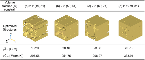
Each optimal design represents a unique configuration that optimizes the performance within the specified material usage requirements (). The objective of the optimization process is to achieve the desired properties, particularly in the -direction. We found that the optimized structures suggested a non-identical material distribution feature in different directions, reflecting the anisotropic properties desired for the application. The optimized designs exhibited specific structural characteristics to achieve an optimal compromise between the two objectives. The material was distributed more continuously in the
-direction to ensure a favorable thermal conductivity. Meanwhile, in the
and
-directions, the material distribution demonstrated reduced continuity compared to the
-direction. The optimal designs aimed to maximize the utilization of the limited material by allocating more of it along the
-direction to enhance the thermal conductivity. This allocation resulted in relatively lower material continuity along the other two directions,
and
, consequently reducing shear compliances. As a result, the geometry feature of the surface perpendicular to
is different from that of the surface perpendicular to
and
, and a microstructure with anisotropic properties is generated. By imposing different volume fraction constraints on the multi-objective topology optimization platform, we were able to tailor the microstructure for different application scenarios accordingly. Instead of randomly generating microstructures using an RVE generator, the topology optimization allowed us to effectively achieve the desired performance while considering resource constraints.
Figure 9. Multi-objective topology optimization using different volume fraction constraints: optimized structures and their properties for =
= 0.5.
4.3. Multi-objective topology optimization for an orthotropic microstructure
Next, We designed an orthotropic microstructures similarly to the anisotropic microstructures. To obtain orthotropic microstructures, shear compliance and thermal compliance in the three directions were considered. The normalized shear and thermal compliances are expressed as follows:
For optimizing the orthotropic microstructures, the volume fraction remains unconstrained, indicating that and
were assigned values of 0 and 1, respectively. The unconstrained volume fraction allows for a more comprehensive exploration of the design space and can potentially lead to efficient material distributions and novel designs. To generate various optimized microstructures, we utilized different weight factors for topology optimization by varying
. Specifically, an increased weight factor of the shear modulus
indicates an increased prioritization of minimizing the shear modulus. When
exceeded the threshold of 0.5, the resulting optimized structure was classified as a design that prioritized shear-modulus minimization. Conversely, by setting
to be less than or equal to 0.5, we obtained a design that prioritized the maximization of thermal conductivity. shows the convergence history for multi-objective topology optimizations with different weight factors. The optimization process begins with the initial design of a homogeneous solid state that exhibits maximal shear and thermal compliance. As the iterations progressed, the objective function decreased drastically in the early stage, and the design was iteratively updated until the variation in the objective function was eventually stable. In this study, the optimization was terminated when the variation in the objective function between successive iterations was less than
for at least three consecutive iterations. The objective function update history indicated that the objective function reached a stable value within 200 iterations for each case. The update histories for the shear compliance denoted by
() and thermal compliance denoted by
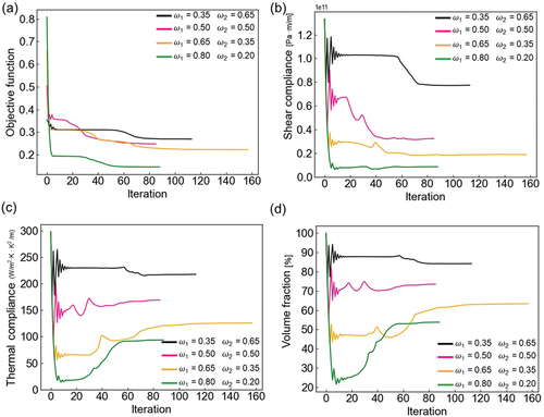
() demonstrate the effectiveness of the optimization algorithm. We also obtained the volume fraction update history (), which indicates a strong correlation between the volume fraction with shear compliance and thermal compliance. In the optimization calculations, the shear compliance was decreasing because it corresponds to decrease the macroscopic shear modulus; simultaneously, the thermal compliance was increased together with the macroscopic thermal conductivity. Also, the suitable volume fractions dependent on the weight factors were searched in consideration of the conflict between minimizing the macroscopic shear modulus and maximizing the macroscopic thermal conductivity.
Figure 10. Convergence history of multi-objective topology optimization using different weight factors: (a) Objective function (b) Shear compliance (c) Thermal compliance, and (d) Volume fraction.
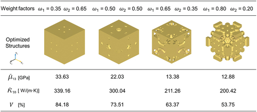
After the optimization, we smoothed the generated microstructures by setting a density threshold of 0.5 (). We found that the weight factors had a significant influence on the optimized microstructures. From the microstructural properties, we observed that in the design that prioritized the minimization of the shear modulus, the shear modulus was significantly lower than that in the design that prioritized maximization of the thermal conductivity, at the cost of the thermal conductivity. From the design that prioritized the minimization of the shear modulus to the design that prioritized the maximization of the thermal conductivity, an increased volume fraction of the optimized microstructure was observed. Our high-throughput evaluation results indicated that a higher volume fraction was advantageous for thermal conductivity maximization but detrimental to shear modulus minimization, which might be the reason for the variation in the volume fraction observed among designs that prioritized minimizing the shear modulus and maximizing the thermal conductivity. Previous findings in our evaluation results are in line with the volume fraction tendency observed in the designs obtained from multi-objective topology optimization.
Figure 11. Multi-objective topology optimization using different weight factors: optimized structures and their properties under orthotropic assumptions.
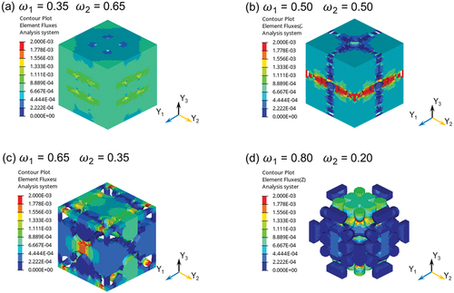
To gain further insights into the optimized microstructures, we performed a finite element analysis to visualize the stress and heat flux distributions of the optimized designs (), where the finite element meshes were generated using automated meshing function with four-node tetrahedral elements in consideration of the periodic boundary conditions same as Section 3.2. The volume fraction of the optimized structure varied when different design priorities were selected, which affected the microstructure stress and flux distribution. From the stress distribution, it is apparent that the stress was smaller in the design with a low volume fraction. This phenomenon could be attributed to the ability of the reduced volume fraction to facilitate the formation of easily deformable structures, thereby enhancing the stress-shielding capabilities, and consequently reducing the stress within the die-bonding material. This result is in accordance with the general concept that a porous microstructure with a low shear modulus is favorable for stress shielding, indicating that the optimization platform provides reasonable results. From the heat flux distribution (), the heat flux was higher in the design that prioritized the maximization of thermal conductivity, indicating a beneficial effect for reducing the harmful heat generated from semiconductors. The designed microstructure that prioritized the maximization of thermal conductivity featured a higher volume fraction, resulting in improved thermal conductivity.
Figure 12. Effect of weight factor on von mises stress of the optimized microstructures under the imposed macroscopic strain mode .
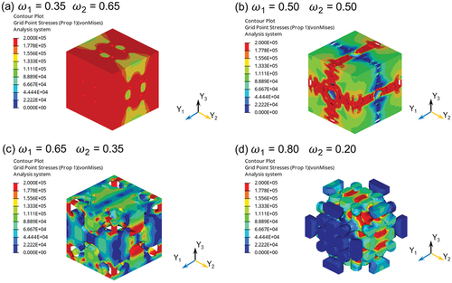
Figure 13. Effect of weight factor on component of heat flux of the optimized microstructures under the applied macroscopic temperature mode
.
4.4. Comparison with results of randomly generated microstructures
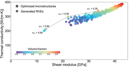
Multi-objective topology optimization is developed with the aim of intelligently designing optimal structures with the best compromise between two conflicting properties. To validate the effectiveness of the multi-objective topology optimization, we calculated the shear modulus and thermal conductivity of the optimized microstructure and compared them with the corresponding values of randomly generated RVEs shown in Section 3. In , the squares and circles represent the shear modulus and thermal conductivity of the optimized structures and generated RVEs, respectively. When the shear moduli of the optimized microstructures and generated RVEs were at the same level, the thermal conductivities of the optimized structures were always higher than those of the randomly generated RVEs. The results revealed the advantage of multi-objective topology optimization compared with the RVEs generator: it can find the optimal design with the best compromised properties. Furthermore, the multi-objective topology optimization can design architected microstructures with a lower shear modulus compared to designs generated by the RVE generator. To illustrate, the multi-objective topology optimization generated microstructures with a shear modulus of 12.88 GPa, which was attributed to the iterative design capability of the optimization algorithm. In contrast, the RVE generator randomly designed microstructures, and none of the microstructures in this study approached this range. Deep-learning studies indicated that random generation algorithm can cover microstructures with extreme properties [Citation56]; however, massive data over 10,000 are usually required for deep-learning. In conclusion, the multi-objective topology optimization is effective in generating designs with compromised properties, and microstructures with a considerably lower shear modulus can be obtained more easily using our multi-objective topology optimization platform.
Figure 14. Comparison between the generated RVEs and optimized microstructures in terms of the shear modulus and thermal conductivity.
5. Conclusion
In this study, we investigated the effect of microscopic morphology on porous microstructures for the die-bonding layer of semiconductors. We employed finite element analyses for periodic microstructure and designed architected microstructures, aiming for a balanced compromise between minimizing shear modulus and maximizing thermal conductivity through the solution of a multi-objective topology optimization problem. Initially, a high-throughput evaluation was conducted using an RVE generator, generating numerous microstructures with randomly distributed pores while controlling pore volume fraction and connectivity. The results indicated that the volume fraction had a significant positive correlation with the macroscopic shear modulus and thermal conductivity, leading to a conflict between the shear modulus minimization and thermal conductivity maximization. Furthermore, in the high-throughput evaluation, pore connectivity exhibited an insignificant correlation with those properties; however, the multi-objective topology optimization yielded microstructures with enhanced material performance. This suggests the efficacy of the optimized design in improving material performance. Consequently, the findings of this study hold the potential to contribute to the enhancement of objective material performance. While the microscopic morphology is controllable to some extent within a fabrication process, reproducing the architected microstructure as is remains challenging. Hence, additional research and development of fabrication processes are imperative to effectively utilize the outcomes of computer-oriented design. Simultaneously, the establishment of a computational design method, considering constraints from the fabrication process, is essential for practical applications.
Acknowledgements
This study was supported by the Altair Research Support program. The authors wish to acknowledge Ms. Y. Yamamoto of the National Institute for Materials Science for her technical support.
Disclosure statement
No potential conflict of interest was reported by the author(s).
References
- Zhang H, Wang W, Bai H, et al. Microstructural and mechanical evolution of silver sintering die attach for SiC power devices during high temperature applications. J Alloys Compd. 2019;774:487–15. doi: 10.1016/j.jallcom.2018.10.067
- Chen C, Nagao S, Zhang H, et al. Mechanical deformation of sintered porous ag die attach at high temperature and its size effect for wide-bandgap power device design. J Electron Mater. 2017;46(3):1576–1586. doi: 10.1007/s11664-016-5200-3
- Barui S, Chatterjee S, Mandal S, et al. Microstructure and compression properties of 3D powder printed Ti-6Al-4V scaffolds with designed porosity: experimental and computational analysis. Mater Sci Eng C. 2017;70:812–823. doi: 10.1016/j.msec.2016.09.040
- Wang L, Kang J, Sun C, et al. Mapping porous microstructures to yield desired mechanical properties for application in 3D printed bone scaffolds and orthopaedic implants. Mater Des. 2017;133:62–68. doi: 10.1016/j.matdes.2017.07.021
- Bidhar S, Kuwazuru O, Shiihara Y, et al. Empirical formulation of stress concentration factor around an arbitrary-sized spherical dual-cavity system and its application to aluminum die castings. Appl Math Modell. 2015;39:5707–5723. doi: 10.1016/j.apm.2015.01.032
- Sigmund O. On the design of compliant mechanisms using topology optimization. J Struct Mech. 1997;25(4):493–524. doi: 10.1080/08905459708945415
- Zhu B, Zhang X, Zhang H, et al. Design of compliant mechanisms using continuum topology optimization: a review. Mech Mach Theory. 2020;143:103622. doi: 10.1016/j.mechmachtheory.2019.103622
- Pereira A, Talischi C, Paulino GH, et al. Fluid flow topology optimization in PolyTop: stability and computational implementation. Struct Multidiscipl Optim. 2016;54:1345–1364. doi: 10.1007/s00158-014-1182-z
- Yaji K, Yamada T, Yoshino M, et al. Topology optimization in thermal-fluid flow using the lattice Boltzmann method. J Comput Phys. 2016;307:355–377. doi: 10.1016/j.jcp.2015.12.008
- Xia Q, Xia L, Shi T. Topology optimization of thermal actuator and its support using the level set based multiple–type boundary method and sensitivity analysis based on constrained variational principle. Struct Multidiscipl Optim. 2018;57(3):1317–1327. doi: 10.1007/s00158-017-1814-1
- Langelaar M, Yoon GH, Kim YY, et al. Topology optimization of planar shape memory alloy thermal actuators using element connectivity parameterization. Int J Numer Methods Eng. 2011;88(9):817–840.
- Bendsøe MP. Optimal shape design as a material distribution problem. Struct Optim. 1989;1(4):193–202. doi: 10.1007/BF01650949
- Allaire G, Jouve F, Toader AM. Structural optimization using sensitivity analysis and a level-set method. J Comput Phys. 2004;194(1):363–393. doi: 10.1016/j.jcp.2003.09.032
- Wang MY, Wang X, Guo D. A level set method for structural topology optimization. Comput Methods Appl Mech Eng. 2003;192(1–2):227–246. doi: 10.1016/S0045-7825(02)00559-5
- Sethian JA, Wiegmann A. Structural boundary design via level set and immersed interface methods. J Comput Phys. 2000;163(2):489–528. doi: 10.1006/jcph.2000.6581
- Van Dijk NP, Maute K, Langelaar M, et al. Level-set methods for structural topology optimization: a review. Struct Multidiscipl Optim. 2013;48(3):437–472.
- Yamada T, Yamasaki S, Nishiwaki S, et al. Design of compliant thermal actuators using structural optimization based on the level set method. J Comput Inf Sci Eng. 2011;11(1):011005. doi: 10.1115/1.3563049
- Li H, Kondoh T, Jolivet P, et al. Three-dimensional topology optimization of a fluid–structure system using body-fitted mesh adaption based on the level-set method. Appl Math Model. 2022;101:276–308. doi: 10.1016/j.apm.2021.08.021
- Zhou J, Watanabe I, Yamada T. Computational morphology design of duplex structure considering interface debonding. Compos Struct. 2022;302:116200. doi: 10.1016/j.compstruct.2022.116200
- Noguchi Y, Yamada T, Izui K, et al. Topology optimization for hyperbolic acoustic meta-materials using a high-frequency homogenization method. Comput Methods Appl Mech Eng. 2018;335:419–471. doi: 10.1016/j.cma.2018.02.031
- Allaire G, Yamada T. Optimization of dispersive coefficients in the homogenization of the wave equation in periodic structures. Numer Math. 2018;140(2):265–326. doi: 10.1007/s00211-018-0972-4
- Huang X, Radman A, Xie YM. Topological design of microstructures of cellular materials for maximum bulk or shear modulus. Comput Mater Sci. 2011;50(6):1861–1870. doi: 10.1016/j.commatsci.2011.01.030
- Yang XY, Huang X, Rong JH, et al. Design of 3D orthotropic materials with prescribed ratios for effective Young’s moduli. Comput Mater Sci. 2013;67:229–237. doi: 10.1016/j.commatsci.2012.08.043
- Andreassen E, Lazarov BS, Sigmund O. Design of manufacturable 3D extremal elastic microstructure. Mech Mater. 2014;69(1):1–10. doi: 10.1016/j.mechmat.2013.09.018
- Huang X, Zhou SW, Xie YM, et al. Topology optimization of microstructures of cellular materials and composites for macrostructures. Comput Mater Sci. 2013;67:397–407. doi: 10.1016/j.commatsci.2012.09.018
- Watanabe I, Nakamura G, Yuge K, et al. Maximization of strengthening effect of microscopic morphology in duplex steels. In : advanced structured materials: from creep damage mechanics to homogenization methods. Cham: Springer; 2015. doi: 10.1007/978-3-319-19440-024
- Chen W, Liu S. Topology optimization of microstructures of viscoelastic damping materials for a prescribed shear modulus. Struct Multidiscipl Optim. 2014;50(2):287–296. doi: 10.1007/s00158-014-1049-3
- Bruggi M, Corigliano A. Optimal 2D auxetic micro-structures with band gap. Meccanica. 2019;54(13):2001–2027. doi: 10.1007/s11012-019-00981-w
- Vogiatzis P, Chen S, Wang X, et al. Topology optimization of multi-material negative Poisson’s ratio metamaterials using a reconciled level set method. Comput Aided Des. 2017;83:15–32. doi: 10.1016/j.cad.2016.09.009
- Zhou S, Li Q. Computational design of multi-phase microstructural materials for extremal conductivity. Comput Mater Sci. 2008;43(3):549–564. doi: 10.1016/j.commatsci.2007.12.021
- Zheng X, Chen TT, Jiang X, et al. Deep learning-based inverse design of three-dimensional architected cellular materials with the target porosity and stiffness using voxelized voronoi lattices. Sci Technol Adv Mater. 2023;24(1):2157682. doi: 10.1080/14686996.2022.2157682
- Pabst W, Uhlířová T, Gregorová E. Shear and bulk moduli of isotropic porous and cellular alumina ceramics predicted from thermal conductivity via cross-property relations. Ceram Int. 2018;444(7):8100–8108. doi: 10.1016/j.ceramint.2018.01.254
- Sigmund O. Design of multiphysics actuators using topology optimization–part I: one- material structures. Comput Methods Appl Mech Eng. 2001;190(49–50):6577–6604. doi: 10.1016/S0045-7825(01)00251-1
- Sigmund O. Design of multiphysics actuators using topology optimization–part II: two-material structures. Comput Methods Appl Mech Eng. 2001;190(49–50):6605–6627. doi: 10.1016/S0045-7825(01)00252-3
- Sato Y, Izui K, Yamada T, et al. Data mining based on clustering and association rule analysis for knowledge discovery in multi-objective topology optimization. Expert Syst Appl. 2019;119:247–261. doi: 10.1016/j.eswa.2018.10.047
- Chen Y, Zhou S, Li Q. Multiobjective topology optimization for finite periodic structures. Comput Struct. 2010;88(11–12):806–811. doi: 10.1016/j.compstruc.2009.10.003
- Cadman JE, Zhou S, Chen Y, et al. On design of multi-functional microstructural materials. J Mater Sci. 2013;48:51–66. doi: 10.1007/s10853-012-6643-4
- Francisco P, Faria L, Simões R. Multi-objective and multi-load topology optimization and experimental validation of homogenized coupled fluid flow and heat transfer and structural stiffness. Struct Multidiscipl Optim. 2020;62(5):2571–2598. doi: 10.1007/s00158-020-02625-0
- Watanabe I, Yamanaka A. Voxel coarsening approach on image-based finite element modeling of representative volume element. Int J Mech Sci. 2019;150:314–321. doi: 10.1016/j.ijmecsci.2018.10.028
- Bargmann S, Klusemann B, Markmann J, et al. Generation of 3D representative volume elements for heterogeneous materials: a review. Prog Mater Sci. 2018;96:322–384. doi: 10.1016/j.pmatsci.2018.02.003
- Zheng X, Guo X, Watanabe I. A mathematically defined 3D auxetic metamaterial with tunable mechanical and conduction properties. Mater Des. 2021;198:109313. doi: 10.1016/j.matdes.2020.109313
- Hassani B, Hinton E. A review of homogenization and topology optimization III—topology optimization using optimality criteria. Comput Struct. 1998;69(6):739–756. doi: 10.1016/S0045-7949(98)00133-3
- Andreassen E, Andreasen CS. How to determine composite material properties using numerical homogenization. Comput Mater Sci. 2014;83:488–495. doi: 10.1016/j.commatsci.2013.09.006
- Zhang J, Peng J, Liu T, et al. Multi-objective periodic topology optimization of thermo- mechanical coupling structure with anisotropic materials by using the element-free Galerkin method. Int J Mech Mater Des. 2022;18(4):939–960. doi: 10.1007/s10999-022-09600-1
- Zhang X, Ye H, Wei N, et al. Design optimization of multifunctional metamaterials with tunable thermal expansion and phononic bandgap. Mater Des. 2021;209:109990. doi: 10.1016/j.matdes.2021.109990
- Alacoque L, Watkins RT, Tamijani AY. Stress-based and robust topology optimization for thermoelastic multi-material periodic microstructures. Comput Methods Appl Mech Eng. 2021;379:113749. doi: 10.1016/j.cma.2021.113749
- Allaire G. Homogenization and two-scale convergence. SIAM J Math Anal. 1992;23(6):1482–1518. doi: 10.1137/0523084
- Allaire G. Mathematical approaches and methods. Homogenization and porous media. New York (NY): Springer; 1996.
- Watanabe I, Terada K. A method of predicting macroscopic yield strength of polycrystalline metals subjected to plastic forming by micro–macro de-coupling scheme. Int J Mech Sci. 2010;52(2):343–355. doi: 10.1016/j.ijmecsci.2009.10.006
- Watanabe I, Setoyama D, Nagasako N, et al. Multiscale prediction of mechanical behavior of ferrite–pearlite steel with numerical material testing. Int J Numer Methods Eng. 2012;89(7):829–845. doi: 10.1002/nme.3264
- Li Y, Yang Q, Chang T, et al. Multi-load cases topological optimization by weighted sum method based on load case severity degree and ideality. Adv Mech Eng. 2020;12(8):1687814020947510. doi: 10.1177/1687814020947510
- Marler RT, Arora JS. The weighted sum method for multi-objective optimization: new insights. Struct Multidiscipl Optim. 2010;41(6):853–862. doi: 10.1007/s00158-009-0460-7
- Ryu N, Seo M, Min S. Multi-objective topology optimization incorporating an adaptive weighed-sum method and a configuration-based clustering scheme. CMAME. 2021;385:114015. doi: 10.1016/j.cma.2021.114015
- Fleury C. Structural weight optimization by dual methods of convex programming. Int J Numer Meth Eng. 1979;14(12):1761–1783. doi: 10.1002/nme.1620141203
- Fleury C. CONLIN: an efficient dual optimizer based on convex approximation concepts. Struct Optim. 1989;1(2):81–89. doi: 10.1007/BF01637664
- Zheng X, Chen T, Guo X, et al. Controllable inverse design of auxetic metamaterials using deep learning. Mater Des. 2021;211:110178. doi: 10.1016/j.matdes.2021.110178