
 ?Mathematical formulae have been encoded as MathML and are displayed in this HTML version using MathJax in order to improve their display. Uncheck the box to turn MathJax off. This feature requires Javascript. Click on a formula to zoom.
ABSTRACT
Optics has advanced through centuries of research into the fundamental properties of light and its interactions with matter. Within this rich history, one optical component stands out: the diffraction grating. Liquid crystals (LCs) have emerged as promising candidates in diffraction gratings. LCs are versatile and adaptable materials influenced by various external factors. Diffractive LC grating devices can be produced through methods such as photo alignment, using polymer walls, or employing patterned electrodes. However, photo alignment poses challenges in terms of manufacturing complexity, and using polymer walls is associated with some drawbacks, such as high driving voltage and slower response times, which must be considered in their application. Currently, research efforts are predominantly focused on manufacturing techniques involving patterned electrodes. In this review, we comprehensively explored the theoretical foundations underpinning diffraction gratings. Additionally, we summarized research on diffractive gratings based on LC using patterned electrodes and conducted a comparative analysis of the characteristics of each device.
1. Introduction
The evolution of optics is a testament to centuries of dedicated exploration into the fundamental properties of light and its interactions with matter. Among the vast array of optical components, diffraction grating [Citation1–11] has emerged as a cornerstone, universally recognized for its pivotal role across diverse scientific disciplines. Its significance lies in the unparalleled ability to manipulate the propagation of light and disperse its spectral components. Diffraction gratings are applied in different fields – ranging from chemistry, where they analyze the presence and concentration of specific substances, to astrophysics, aiding in identifying elements within celestial bodies, and telecommunications, enhancing the data-carrying capacity of optical fibers [Citation12–19]. However, modern applications demand adaptable and easily adjustable gratings in response to external stimuli, suggesting the need for an ongoing quest for innovation.
Liquid crystal (LC) has surfaced as a promising candidate for diffraction gratings, owing to its versatility and adaptability [Citation20–24]. Influenced by various external factors, LCs exhibit diverse textures dependent on factors such as geometric confinement and applied external stimuli. Additionally, LCs display birefringence, indicating multiple distinct refractive indices corresponding to different propagation directions and polarizations within the medium [Citation24–32]. This property enables light to undergo double refraction, splitting into two rays, each traveling at different velocities. The remarkable optical properties of LCs position them as outstanding candidates for diffraction gratings.
This comprehensive review aims to explore the theoretical foundations that underpin diffraction gratings. By unraveling the intricate principles governing the interaction of light with these gratings, we aim to provide a profound analysis of their optical behavior and functionalities. Furthermore, this review centers on a meticulous comparative analysis of various LC grating devices. Through re-simulation and detailed contrast, we elucidate the distinctive features of one-dimensional, two-dimensional, and waffle-shaped LC grating configurations. These exemplary devices, leveraging patterned electrodes, are crucial in the evolving landscape of LC-based diffractive optics. This comparative study highlights the nuanced advantages and potential applications of each grating design. By scrutinizing their performance under different conditions and external stimuli, we contribute valuable insights that may inform future advancements in diffractive optics.
2. General principles of diffraction gratings
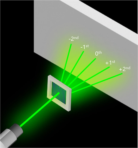
When a green light ray penetrates a grating with slit spacing and makes an angle with the grating normal, it diffracts by the slits. A key characteristic of diffraction gratings is their ability to ensure constructive interference for each diffracted ray when the geometric path difference is a multiple of the wavelength of light. Consequently, a unique set of angles, correlated with the incident angle and the diffracted orders (for each order, with m = 0, ±1, ±2, …), becomes visible. The general principle of a diffraction grating is illustrated in Figure .
Figure 1. Schematic representation of the grating structure inducing diffraction in incident green light.
Transitioning from this general principle to liquid crystal (LC) grating devices, LCs exhibit distinct characteristics wherein the diffraction efficiency and angle change depend on the retardation of LC and the grating period, respectively [Citation29–34]. Describing these characteristics involves applying the diffraction law of Bragg, expressed as mλ = 2Λsin(θ), where m is the diffraction order, λ is the wavelength of light, Λ is the grating period, and θ is the diffraction angle [Citation35,Citation36]. This equation elucidates the alignment of LC particles forming a grating, causing specific wavelengths of light to diffract based on the grating spacing and diffraction angle. The relationship between diffraction efficiency and incident angle is governed by diffraction efficiency, which is directly proportional to sin2(θ), where an increase in retardation results in higher diffraction efficiency for higher diffraction orders (m) [Citation37,Citation38]. Investigating the first-order diffraction angle, as depicted in Figure , reveals that an increase in the grating period Λ is accompanied by a decrease in the diffraction angle θ. This relationship is accurately described by sin(θ) = λ/Λ.
Figure 2. Diffraction angles (dots and line represent simulated and calculated results, respectively) at the first order of the LC grating device as a function of the grating period Λ.
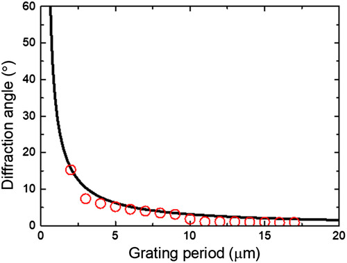
Considering the Fringe Field Switching (FFS) mode, exceeding a certain threshold in the distance (grating period) between the two electrodes may disrupt the electric field formation [Citation39–43]. This disruption, as indicated by the red dots in the graph, significantly and rapidly reduces the diffraction angle when the grating period is configured at 11 µm or more.
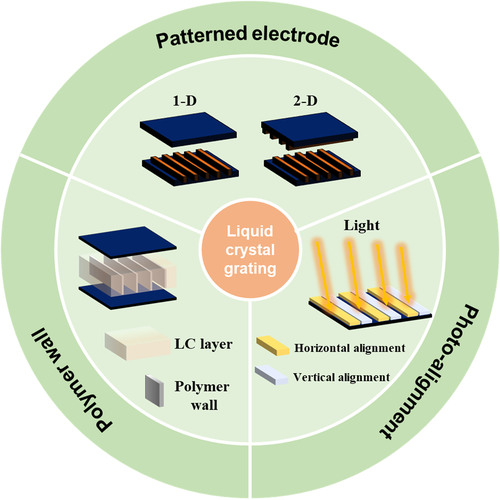
Earlier studies focused on creating diffraction grating devices using polymers, such as polymer-dispersed LCs (PDLC), comprising LC droplets embedded in a polymer matrix. To use PDLC as a diffraction grating device, segregating the polymer from the LC component is essential, as depicted in Figure . However, despite several studies on enhancing polymer-based devices, there is an increasing demand for materials with high diffraction efficiencies, large switching fields, and fast response times [Citation44–51]. An alternative approach involves periodically aligning the initial state of LCs orthogonally through photoalignment [Citation52]. Although this technique, devoid of polymer utilization, exhibits a comparatively lower driving voltage and faster response time, challenges such as manufacturing complexity and low reliability accompany photoalignment. While overcoming these drawbacks, the current research efforts predominantly focus on manufacturing techniques employing patterned electrodes, as shown in Figure [Citation53].
Figure 3. Overview of various LC diffractive grating devices, including LC/polymer composites, photo-aligned LC cells, and LC cells with patterned electrodes.
In summary, this fundamental exploration has provided insights into the intricate principles governing diffraction gratings, specifically exploring LC grating devices and their unique characteristics. The subsequent sections will elaborate on alternative fabrication methods and differentiate various LC grating configurations.
3. Focus on LC devices using patterned electrode
3.1. One-Dimensional (1-D) LC grating device
In 2017, T.-H. Choi et al. [Citation54] introduced a phase grating with switchable diffraction angles utilizing patterned electrodes on one of two substrates, as depicted in Figure (a). This study discerns the significance of the rubbing angle (α) in a homogeneously aligned FFS cell, establishing that α = 0 is the optimal choice for diffraction grating applications. Consequently, our focus is exclusively on FFS with α = 0. This study’s numerical computations combined the finite-element method and the 2 × 2 extended Jones matrix method, implemented through TechWiz LCD, a commercial software developed by Sanayi System Company, Ltd., in Korea. The general form of the extended Jones matrix is described as follows:
(1)
(1) where the matrix elements Mij, represent the individual components of the overall transfer matrix obtained by sequentially multiplying all the 2 × 2 matrices. The transmitted energy fraction (T) is given by
and depends on the matrix elements Mij and the polarization state of the incident beam (i.e. As, Ap). In practical scenarios, unpolarized light is common. In such cases, the Jones vector of the incident beam can be expressed as
(2)
(2) where α1 and α2 are considered random, such that the time-averaged quantities [cos (α1 – α2)] and [sin (α1 – α2)] average out to zero. Consequently, the fraction of transmitted energy, T, is given by (|M11|2 + |M12|2 + |M21|2 + |M22|2)/2 [Citation55–57]. The study’s subsequent sections apply these formulas.
Choi et al. [Citation54] found that the width of the patterned electrodes was 2.8 μm, and the gap between them was 4 μm. The LC material (Merck E7) parameters were elastic constants K11 = 11.1 pN, K22 = 10.3 pN, K33 = 17.1 pN; the optical anisotropy Δn = 0.2253 (ne = 1.746, no = 1.522 at 589 nm, 20 °C); the dielectric anisotropy Δε = 13.8(= 19,
= 5.2); and the rotational viscosity γ1 = 250 mPa·s. To achieve uniform LC alignment, a thin polyimide layer was applied to each substrate through spin-coating, followed by baking at 230°C for 30 minutes. An antiparallel rubbing procedure resulted in a pretilt angle of 2°. Nematic LCs were introduced into each cell through capillary action, maintaining a consistent cell gap of 5 μm. Here, we reproduced some characteristics using the parameters specified in Figure .
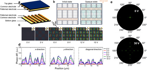
Figure 4. 1-D LC grating device: (a) device structure; (b) calculated LC director distributions; (c) calculated POM images with a full-wave plate; (d) calculated phase difference profiles; and (e) simulated diffraction pattern.
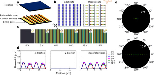
A non-switching region, forming a virtual wall of liquid crystals, emerges between the center of the patterned electrode and the electrode (refer to Figure (b)). This region functions as a grating structure, inducing the diffraction phenomenon. To observe the electrically modulated refractive index profile, we simulated the POM image on the 1-dimensional (1-D) grating device (Figure (c)). With applied voltages incrementing from 0 to 15 V at 3 V intervals, noticeable changes occurred in LC molecules near the edges of the patterned electrodes, manifesting in distinct colors (green and yellow). Conversely, LC molecules at the center of each electrode and in the middle of the gaps maintained their original alignment, displaying a black color.
The initially aligned LC molecules rotated along the electric field directions facilitated by the patterned electrode. Consequently, a spatial phase difference developed along the vertical directions. This phase grating device exhibits high performance, featuring a low voltage and a large diffraction angle. This performance is attributed to the induction of a spatial phase difference caused by a change in the refractive index of the LC layer at a low voltage [Citation53].
Phase difference profiles were computed in the vertical, horizontal, and diagonal directions at applied voltages (Figure (d)). Considering that the 1-D grating device applies an electric field in one of two directions (x – and y-axis) determined by the orientation of the patterned electrode, it represents the spatial phase difference in 1-D. The re-simulated 1-D grating device demonstrates maximum spatial phase differences of 283.83 and 225.83 nm in the horizontal and diagonal directions, respectively.
Diffraction patterns were observed on a dark screen when an unpolarized laser beam (543.5 nm) passed through the LC cell (Figure (e)). Due to the majority of the laser energy directed to higher orders in the horizontal direction, the intensity of the zeroth order was significantly reduced. The efficient transport of diffraction energy from the zeroth order to the higher order was evident. The spatial phase difference indicates the potential for the 1-D grating cell with a patterned electrode to transition to an opaque state.
3.2. Two-Dimensional (2-D) LC grating device
To extend beyond the limited characteristics of 1-D grating devices, T.-H. Choi et al. [Citation58] further investigated a 2-dimensional (2-D) grating device in 2018. The objective was to overcome the limitations of 1-D configurations by introducing patterned electrodes on both substrates at perpendicular angles to each other, as exemplified in Figure (a). This configuration aimed to establish a 2-D electric field, enabling 2-D switching of LC. In the reference, the 2-D grating device featured interdigitated electrodes with a width, pitch, and height of 2.8, 4 μm, and 50 nm, respectively. The dielectric layer thickness between the interdigitated and common electrodes was 150 nm. Numerical calculations utilized LC material parameters from Merck E7: elastic constants K11 = 11.1 pN, K22 = 10.3 pN, and K33 = 17.1 pN, the optical anisotropy Δn = 0.2253, the dielectric anisotropy Δε = 13.8, and the rotational viscosity γ1 = 250 mPa·s. The thickness of the LC layer was set to 5 μm.
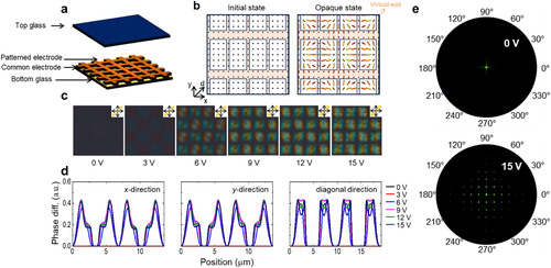
Figure 5. 2-D LC grating device: (a) device structure; (b) calculated LC director distributions; (c) calculated POM images with a full-wave plate; (d) calculated phase difference profiles; and (e) simulated diffraction pattern.
In stark contrast to the 1-D grating device, the 2-D grating device revolutionizes the application of patterned electrodes. By deploying these electrodes on the top and bottom substrates at perpendicular angles, the device achieves an intricate interplay of electric fields in the x and y directions, establishing virtual walls vertically and horizontally (refer to Figure (b)). While the 1-D grating device substantially reduces the light intensity of the zeroth order for the horizontal direction, channeling laser energy into higher-order modes, the intensity of the zeroth order remains unaltered for the vertical direction, where refractive index modulation is absent. Intriguingly, the 2-D grating device exhibits an electrically modulated refractive index profile in vertical and horizontal directions, a noteworthy departure from its 1-D counterpart, as reflected in the POM image (Figure (c)).
To underscore the superior performance of the 2-D grating device over its 1-D counterpart, we evaluated identical characteristics previously confirmed with the 1-D grating device. Figure (d) showcases substantial spatial phase differences observed in all directions: along the x-axis (231.38 nm), the y-axis (227.52 nm), and the diagonal (238.54 nm). In the 2-D grating device, a significant proportion of laser energy is strategically directed toward higher diffraction orders, reducing the intensity of the zeroth order, regardless of polarization direction. Notably, when a laser beam with diagonal polarization relative to the crossed interdigitated electrodes is incident upon a 2-D grating device, a pronounced diffraction effect ensues, owing to a spatial phase difference far surpassing that of a 1-D grating device (Figure (e)). This phenomenon effectively redirects diffraction energy from the zeroth order to higher orders, promising heightened opaque characteristics.
However, a critical caveat appears – the manufacturing of 2-D grating devices poses an imposing challenge, which is primarily rooted in the need for a precise alignment of patterned electrodes on the top and bottom substrates at perfect right angles. This precision is paramount for unleashing the full potential of the 2-D grating device, making its production more complicated.
3.3. Waffle-shaped LC grating device
Our paper published in 2022 [Citation59] proposed a simple but novel approach to address the limitations of 1-D and 2-D configurations while leveraging their respective advantages. This approach used a waffle-shaped patterned electrode and the VA of the LC to create a two-dimensional electric field (Figure (a)), generating significant spatial phase difference while utilizing only one of the two substrates. To achieve the study’s objective, the waffle-shaped grating cell had positive nematic LC (such as E7, Merck) (dielectric anisotropy Δε = 13.8, refractive indices no = 1.52 and ne = 1.75, elastic constants K11, K22, and K33 are 10.3, 7.4, and 16.5 pN, respectively) and octothorp electrode on the bottom substrate. The patterned electrode was 2.8 µm in width, 4 µm in length, and had a cell gap of 20 µm. Additionally, we configured key parameters in the TechWiz LCD 3D software, specifying a pretilt angle of 90°, an azimuthal angle of 1°, and a wavelength of 543.5 nm. Far-field intensity measurements were performed using a photodiode situated 30 cm away from the LC cell.
Figure 6. 2-D LC grating device with waffle-shaped electrodes: (a) device structure; (b) calculated LC director distributions; (c) calculated POM images with a full-wave plate; (d) calculated phase difference profiles; and (e) simulated diffraction pattern.
The waffle-shaped LC grating device introduces a distinctive approach, where initially vertically aligned LC molecules undergo controlled tilting in response to the intricately patterned waffle-shaped electrode. This controlled tilting engenders a substantial spatial phase difference along the vertical, horizontal, and diagonal directions. Figure (b) represents the well-structured virtual wall, akin to the arrangement observed in the 2-D grating device. Upon scrutinizing the POM image, which delineates the electrically modulated refractive index profile and LC molecule rotation, noteworthy similarities with the 2-D grating device become apparent (refer to Figure (c)).
The suggested grating device, propelled by the patterned electrode inducing a more pronounced realignment of LC molecules along the electric field direction, exhibits a consistent spatial phase difference along the vertical (416.37 nm) and horizontal (416.94 nm) directions, as well as in the diagonal orientation (434.20 nm), as portrayed in Figure (d). A distinct diffraction effect is conspicuous, primarily attributed to a spatial phase difference closely mirroring that of a 2-D grating cell. Figure (e) accentuates the significant redistribution of diffraction energy from the zeroth order to higher orders, irrespective of the polarization direction. Accordingly, a substantial spatial phase difference materializes when an electric field is applied to this grating device, disregarding the azimuth angle. As a result, when light permeates the grating device, it diffracts, facilitating the seamless transition of the LC cell to an opaque state. This transition is driven by the pronounced spatial phase difference, a feature resilient to changes in the azimuth angle and ensuring the versatility of the device under varied conditions.
4. Compare the characteristics of the 1-D, 2-D, and waffle-shaped grating devices
Our comparative assessment first examined the haze value – a critical metric in applications such as smart windows. The haze measurement was carried out like how the conventional traditional scattering haze measurement method was done. The calculation of haze from diffraction can be determined by the formula Haze = Td/Tt, where Td is the diffuse transmittance, and Tt is the total transmittance [Citation58,Citation59]. The maximum haze values for the 1-D, 2-D, and waffle-shaped grating devices were determined as 51.20%, 88.18%, and 76.77%, with driving voltages of 7.5, 10, and 17.5 V, respectively (refer to Figure ). The 1-D grating device, characterized by a periodic refractive index distribution perpendicular to the interdigitated ITO electrodes, demonstrated minimal refractive index modulation induced by these transparent electrodes. Consequently, the majority of incident light energy passed through the cell without significant interference, resulting in a low haze value in its translucent state. The 2-D grating device, with patterned electrodes on both substrates, displayed a higher spatial phase difference than the waffle-shaped grating device, slightly increasing the haze value. Hence, to respond to the low haze characteristics, the current research revealed an increased haze value of 94.36% by applying asymmetrically anchoring energy to the waffle-shaped grating device for a more extensive spatial phase difference [Citation60,Citation61].
Figure 7. Simulated diffraction pattern of the 1-D, 2-D, and waffle-shaped grating devices.
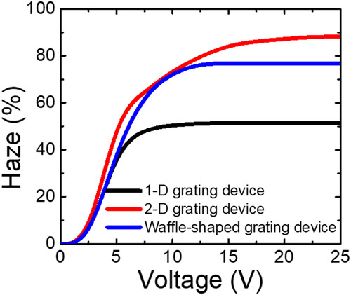
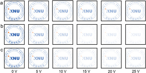
Image analysis within TechWiz LCD 3D revealed the images of the LC grating devices placed atop the attached images (KNU logo) at varying applied voltages (Figure ). At 20 V, all grating devices transitioned to an opaque state, maintaining partial visibility of the logo. However, this phenomenon is our assumption of a fixed object distance of 30 cm in the calculation. In real-world settings, we anticipate that the 2-D and waffle-shaped grating devices will exhibit complete opacity.
Figure 8. Calculated images of the (a) 1-D, (b) 2-D, and (c) waffle-shaped grating devices with KNU logos.
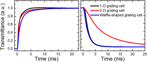
In terms of examining response times, the calculated turn-on [turn-off] times for the 1-D, 2-D, and waffle-shaped grating devices were 2.23 ms [3.56 ms], 3.23 ms [18.6 ms], and 3.79 ms [3.78 ms], respectively (Figure ). The 2-D grating cell, utilizing patterned electrodes on the top and bottom substrates, experienced slightly slower response times due to LCs assuming random orientations in the bulk region. Contrarily, the 1-D and waffle-shaped grating devices with a single substrate with a patterned electrode showcased smaller switching areas for LCs, contributing to faster response times.
Figure 9. Calculated response time of the 1-D, 2-D, and waffle-shaped grating devices.
5. Future directions
To integrate LC diffractive gratings into flexible and stretchable devices, we encountered significant challenges in using patterned electrodes. The inherent rigidity and limited deformability of conventional electrodes impede their application in devices that demand high flexibility. A promising alternative lies in utilizing polymer protrusions to induce haze, thereby circumventing the limitations posed by patterned electrodes. This approach maintains the structural integrity of flexible devices and enhances their optical versatility.
Our current methodology leverages diffraction to achieve a scattering effect, effectively obscuring the background. While this technique is adept at simulating scattering from a distance, it introduces noticeable color dispersion upon closer inspection. This phenomenon poses a significant hurdle for applications in augmented reality (AR) and virtual reality (VR), where precise color rendering and clarity are paramount.
To address this challenge, future researchers should concentrate on developing novel strategies to minimize or eliminate color dispersion in close-range viewing conditions. For instance, they may explore advanced materials or nanostructures that can modulate diffraction properties in a controlled manner. Alternatively, innovative design approaches that adjust the spatial frequency of the diffractive elements might prove effective in mitigating undesired color dispersion. By tackling these issues, we can essentially broaden the applicability of liquid crystal diffractive gratings, particularly in next-generation AR and VR devices, where the integration of flexible and distortion-free optical components is crucial.
6. Conclusion
This comprehensive review unraveled the fundamental concepts underlying light dispersion by grating structures and scrutinized the unique properties of the generated light. Our exploration extended to diverse LC grating devices, including 1-D, 2-D, and waffle-shaped configurations, each harnessing patterned electrodes to induce diffraction. The 1-D devices showcased notable advantages, such as swift response times and streamlined manufacturing processes. However, a trade-off emerged, manifesting in reduced haze characteristics compared to their 2-D and waffle-shaped counterparts. This limitation stemmed from the predominantly confined phase differences to either the vertical or horizontal dimensions in 1-D grating devices. It is imperative to acknowledge a significant challenge in fabricating 2-D grating devices – the intricate demand for precise alignment of the top and bottom pattern electrodes in an orthogonal orientation during manufacturing. This complexity poses a formidable obstacle in using 2-D grating devices. Through our meticulous comparative analysis, the waffle-shaped grating device seemed as the optimal choice among LC grating devices utilizing patterned electrodes since the device exhibited remarkable characteristics and proved to be readily manufacturable.
Looking ahead, future research should aim to streamline the fabrication processes of 2-D grating devices, exploring innovative techniques to address the challenges associated with precise electrode alignment. Moreover, there is a promising avenue for research in enhancing the haze characteristics of 1-D grating devices, potentially by modifying the electrode design or incorporating novel materials. Additionally, investigations into alternative manufacturing approaches that maintain the outstanding characteristics of the waffle-shaped grating device while potentially simplifying the production process would be invaluable. These future endeavors hold the key to unlocking even greater potential in LC-based diffractive optics and expanding their applications across diverse scientific and technological domains.
Disclosure statement
No potential conflict of interest was reported by the author(s).
Additional information
Funding
Notes on contributors

Chan-Hee Han
Chan-Hee Han received his B.S. and M.E. (Electrical Information Communication Engineering) degrees from Kangwon National University (KNU) in Samcheok, Republic of Korea in 2022 and 2024. He is currently a Ph.D. degree student at the Center of Smart Display & Soft Electronics (CSS) research group of POSTECH. His research interests include diffractive liquid crystal and chiral liquid crystal devices.

Sang-Hee Lee
Sang-Hee Lee received a B.S. degree in electrical information communication engineering from Kangwon National University (KNU) in Samcheok, Republic of Korea in 2024. He is currently a master’s degree student at KNU. His research interests include a smart window utilizing diffraction and polarization rotators.
Sunghyun Bae
Sunghyun Bae received a B.S. degree in Electonic Engineering from Sogang University, Seoul, South Korea, in 2013, as well as the M.S. and Ph.D. degrees in Electrical Engineering from Korea Advanced Institute of Science and Technology (KAIST), Daejeon, Korea, in 2015 and 2020, respectively. From 2021 to 2022, he was with Samsung Electronics, Hwaseong, South Korea, as a Staff Engineer, where he was involved in the implementation of an optical proximity correction (OPC) technique for the design of 10-nm class DRAMs. He was a postdoctoral research fellow at KAIST and Electronics and Telecommunication Research Institute (ETRI) in 2020 and 2022, respectively. Since 2022, he has been an Assistant Professor at the Department of Electronics Information & Communication Engineering, Kangwon National University, Samcheok, South Korea. His research interests include high-speed optical access networks, data-center interconnects, and quantum key distribution (QKD) systems.

Jae Won Lee
Jae Won Lee received his B.S. and Ph.D. degrees in Materials Science and Engineering from the Ulsan National Institute of Science and Technology. He was a postdoctoral fellow at Yonsei University. He is an assistant professor at Kangwon National University. His research interests are mainly focused on energy harvesting for self-powered systems.

Seung-Won Oh
Seung-Won Oh received his B.S. and Ph.D. degrees in electronics engineering from Pusan National University, in 2013 and 2018, respectively. From 2019 to 2020, he was a postdoctoral researcher at Liquid Crystal Institute, Kent State University, OH, USA. In 2020–2021 and at the Wave Array and Display Engineering (WADE) Laboratory of Pohang University of Science and Technology. He is currently an associate professor at Kangwon National University. His research interests include self-shading windows for energy saving, liquid crystal cells for photonics, liquid crystal elastomers, and antennas with liquid crystals.
References
- M.J. Lockyear, A.P. Hibbins, K.R. White, and J.R. Sambles, One-way diffraction grating, Phys. Rev. E 74 (5), 056611 (2006).
- E.G. Loewen, and E. Popov, Diffraction Gratings and Applications. (CRC Press, Boca Raton, 2018).
- C.H. Wilcox, Scattering Theory for Diffraction Gratings (Springer Science & Business Media, Berlin, 2012), p. 46.
- G. Bao, P. Li, and J. Lv, Numerical solution of an inverse diffraction grating problem from phaseless data, JOSA A 30 (3), 293–299 (2013).
- J. Chandezon, G. Raoult, and D. Maystre, A new theoretical method for diffraction gratings and its numerical application, J. Opt. 11 (4), 235–241 (1980).
- N. Bonod, and J. Neauport, Diffraction gratings: from principles to applications in high-intensity lasers, Adv. Opt. Photonics 8 (1), 156–199 (2016).
- J.E. Harvey, and R.N. Pfisterer, Understanding diffraction grating behavior: including conical diffraction and Rayleigh anomalies from transmission gratings, Opt. Eng. 58 (8), 087105-21 (2019).
- C. Grünzweig, F. Pfeiffer, O. Bunk, T. Donath, G. Kühne, G. Frei, M. Dierolf, and C. David, Design, fabrication, and characterization of diffraction gratings for neutron phase contrast imaging, Rev. Sci. Instrum. 79 (5), 053703-6 (2008).
- G.W. Stroke, Diffraction gratings, Handb. Phys. 29, 426–754 (1967).
- E.W. Palmer, M.C. Hutley, A. Franks, J.F. Verrill, and B. Gale, Diffraction gratings (manufacture), Rep. Prog. Phys 38 (8), 975–1048 (1975).
- K. Kim, S.-U. Kim, M.-Y. Choi, M.H. Saeed, Y. Kim, J.-H. Na, Voxelated opto-physically unclonable functions via irreplicable wrinkles, Light Sci. Appl. 12 (1), 245 (2023).
- M.H. Saeed, S. Zhang, Y. Cao, L. Zhou, J. Hu, I. Muhammad, J. Xiao, L. Zhang, and H. Yang, Recent advances in the polymer dispersed liquid crystal composite and its applications, Molecules 25 (23), 5510 (2020).
- M.H. Saeed, M.-Y. Choi, K. Kim, J.-H. Lee, K. Kim, D. Kim, S.-U. Kim, H. Kim, S.-k. Ahn, R. Lan, and J.-H. Na, Electrostatically powered multimode liquid crystalline elastomer actuators, ACS Appl. Mat. Interfaces. 15 (48), 56285–56292 (2023).
- R.C. Bailey, J.M. Nam, C.A. Mirkin, and J.T. Hupp, Real-time multicolor DNA detection with chemoresponsive diffraction gratings and nanoparticle probes, J. Am. Chem. Soc. 125 (44), 13541–13547 (2003).
- A.M. Massari, K.J. Stevenson, and J.T. Hupp, Development and application of patterned conducting polymer thin films as chemoresponsive and electrochemically responsive optical diffraction gratings, J. Electroanal. Chem. 500 (1-2), 185–191 (2001).
- A. Hettwer, J. Kranz, and J. Schwider, Three channel phase-shifting interferometer using polarization-optics and a diffraction grating, Opt. Eng. 39, 960–966 (2000).
- J.A. Walker, The future of MEMS in telecommunications networks, J. Micromech. Microeng. 10 (3), R1–R7 (2000).
- T. Loukina, S. Massenot, R. Chevallier, K. Heggarty, N.M. Shigapova, and A.F. Skochilov, Volume diffraction gratings for optical telecommunications applications: design study for a spectral equalizer, Opt. Eng. 43 (11), 2658–2665 (2004).
- J. Zimmer, A. Wixforth, H. Karl, and H.J. Krenner, Ion beam synthesis of nanothermochromic diffraction gratings with giant switching contrast at telecom wavelengths, Appl. Phys. Lett. 100 (23), 231911-5 (2012).
- T.O. Carroll, Liquid-Crystal Diffraction Grating, J. Appl. Phys. 43 (3), 767–770 (1972).
- J. Sun, A.K. Srivastava, L. Wang, V.G. Chigrinov, and H.S. Kwok, Optically tunable and rewritable diffraction grating with photoaligned liquid crystals, Opt. Lett. 38 (13), 2342–2344 (2013).
- Z.G. Zheng, Y. Li, H.K. Bisoyi, L. Wang, T.J. Bunning, and Q. Li, Three-dimensional control of the helical axis of a chiral nematic liquid crystal by light, Nature 531 (7594), 352–356 (2016).
- H.J. Sohn, S.W. Oh, Y. Choi, S.M. Ji, and T.H. Yoon, A switchable cholesteric phase grating with a low operating voltage, Crystals 11 (2), 100 (2021).
- A. Ryabchun, A. Bobrovsky, J. Stumpe, and V. Shibaev, Rotatable diffraction gratings based on cholesteric liquid crystals with phototunable helix pitch, Adv. Opt. Mater. 3 (9), 1273–1279 (2015).
- R. Dąbrowski, P. Kula, and J. Herman, High birefringence liquid crystals, Crystals 3 (3), 443–482 (2013).
- D. Węgłowska, P. Kula, and J. Herman, High birefringence bistolane liquid crystals: synthesis and properties, RSC Adv. 6 (1), 403–408 (2016).
- D.K. Yang, and S.T. Wu, Fundamentals of liquid crystal devices, (JWS, New York, 2014).
- P.J. Collings, and J.W. Goodby, Introduction to Liquid Crystals: Chemistry and Physics (CRC Press, Boca Raton, 2019).
- J. Beeckman, K. Neyts, and P.J. Vanbrabant, Liquid-crystal photonic applications, Opt. Eng. 50 (8), 081202 (2011).
- V.A. Belyakov, V.E. Dmitrienko, and V.P. Orlov, Optics of cholesteric liquid crystals, Sov. Phys. Usp. 22 (2), 64–88 (1979).
- K.A. Rutkowska, and A. Kozanecka-Szmigiel, Design of tunable holographic liquid crystalline diffraction gratings, Sensors 20 (23), 6789 (2020).
- L. Xu, J. Zhang, and L.Y. Wu, Influence of phase delay profile on diffraction efficiency of liquid crystal optical phased array, Opt. Laser Technol. 41 (4), 509–516 (2009).
- O. Köysal, M. Okutan, and M. Gökçen, Investigation of dielectric properties and diffraction efficiency enhancements caused by photothermal effect in DR9 dye-doped nematic liquid crystal, Opt. Commun. 284 (20), 4924–4928 (2011).
- J.J. Butler, and M.S. Malcuit, Diffraction properties of highly birefringent liquid-crystal composite gratings, Opt. Lett. 25 (6), 420–422 (2000).
- A. Othonos, Fiber bragg gratings, Rev. Sci. Instrum. 68 (12), 4309–4341 (1997).
- L.R.B. Elton, and D.F. Jackson, X-ray diffraction and the Bragg law, Am. J. Phys. 34 (11), 1036–1038 (1966).
- J. Kacher, C. Landon, B.L. Adams, and D. Fullwood, Bragg's Law diffraction simulations for electron backscatter diffraction analysis, Ultramicroscopy 109 (9), 1148–1156 (2009).
- F. Rustichelli, On the deviation from the Bragg law and the widths of diffraction patterns in perfect crystals, Philos. Mag. 31 (1), 1–12 (1975).
- D.H. Kim, Y.J. Lim, D.E. Kim, H. Ren, S.H. Ahn, and S.H. Lee, Past, present, and future of fringe-field switching-liquid crystal display, J. Inf. Disp. 15 (2), 99–106 (2014).
- S.H. Lee, S.L. Lee, and H.Y. Kim, Electro-optic characteristics and switching principle of a nematic liquid crystal cell controlled by fringe-field switching, Appl. Phys. Lett. 73 (20), 2881–2883 (1998).
- Y. Chen, Z. Luo, F. Peng, and S.T. Wu, Fringe-field switching with a negative dielectric anisotropy liquid crystal, Journal of Display Technology 9 (2), 74–77 (2013).
- D. Xu, G. Tan, and S.T. Wu, Large-angle and high-efficiency tunable phase grating using fringe field switching liquid crystal, Opt. Express 23 (9), 12274–12285 (2015).
- H.J. Yun, M.H. Jo, I.W. Jang, S.H. Lee, S.H. Ahn, and H.J. Hur, Achieving high light efficiency and fast response time in fringe field switching mode using a liquid crystal with negative dielectric anisotropy, Liq. Crys. 39 (9), 1141–1148 (2012).
- M. Mucha, Polymer as an important component of blends and composites with liquid crystals, Prog. Polym. Sci. 28 (5), 837–873 (2003).
- T.J. Bunning, L.V. Natarajan, V.P. Tondiglia, and R.L. Sutherland, Holographic polymer-dispersed liquid crystals (H-PDLCs), Annu. Rev. Mater. Sci. 30 (1), 83–115 (2000).
- R.L. Sutherland, L.V. Natarajan, V.P. Tondiglia, and T.J. Bunning, Bragg gratings in an acrylate polymer consisting of periodic polymer-dispersed liquid-crystal planes, Chem. Mater. 5 (10), 1533–1538 (1993).
- G. Zharkova, I. Samsonova, S. Streltsov, V. Khachaturyan, A. Petrov, and N. Rudina, Electro-optical characterization of switchable Bragg gratings based on nematic liquid crystal–photopolymer composites with spatially ordered structure, Microelectron. Eng. 81 (2-4), 281–287 (2005).
- K. Beev, L. Criante, D.E. Lucchetta, F. Simoni, and S. Sainov, Recording of evanescent waves in holographic polymer dispersed liquid crystals, J. Opt. A: Pure Appl. Opt. 8 (2), 205–207 (2006).
- R.A. Ramsey, and S.C. Sharma, Switchable holographic gratings formed in polymer-dispersed liquid-crystal cells by use of a He–Ne laser, Opt. Lett. 30 (6), 592–594 (2005).
- J. Qi, and G.P. Crawford, Holographically formed polymer dispersed liquid crystal displays, Displays 25 (5), 177–186 (2004).
- M.S. Park, and B.K. Kim, Transmission holographic gratings produced using networked polyurethane acrylates with various functionalities, Nanotechnology 17 (8), 2012–2017 (2006).
- W. Hu, A. Kumar Srivastava, X.W. Lin, X. Liang, Z.J. Wu, J.T. Sun, and Y.Q. Lu, Polarization independent liquid crystal gratings based on orthogonal photoalignments, Appl. Phys. Lett. 100 (11), 111116-4 (2012).
- H. Chen, G. Tan, Y. Huang, Y. Weng, T.H. Choi, T.H. Yoon, and S.T. Wu, A low voltage liquid crystal phase grating with switchable diffraction angles, Sci. Rep. 7 (1), 39923 (2017).
- T.H. Choi, J.H. Woo, J.M. Baek, Y. Choi, and T.H. Yoon, Fast control of haze value using electrically switchable diffraction in a fringe-field switching liquid crystal device, IEEE Trans. Electron Devices 64 (8), 3213–3218 (2017).
- P. Yeh, Extended Jones matrix method, J. Opt. Soc. Am. 72 (4), 507–513 (1982).
- C. Gu, and P. Yeh, Extended Jones matrix method. II, JOSA A 10 (5), 966–973 (1993).
- I. Moreno, M.J. Yzuel, J. Campos, and A. Vargas, Jones matrix treatment for polarization Fourier optics, J. Mod. Opt 51 (14), 2031–2038 (2004).
- T.-H. Choi, J.-H. Woo, B.-G. Jeon, J. Kim, M. Cha, and T.-H. Yoon, Fast fringe-field switching of vertically aligned liquid crystals between high-haze opaque and haze-free transparent states, Liq. Cryst. 45 (10), 1419–1427 (2018).
- C.H. Han, H. Eo, T.H. Choi, W.S. Kim, and S.W. Oh, A simulation of diffractive liquid crystal smart window for privacy application, Sci. Rep. 12 (1), 11384 (2022).
- C.H. Han, T.H. Choi, W.S. Kim, and S.W. Oh, Diffractive liquid crystal device for privacy window with a low operating voltage, J. Inf. Disp. 24 (4), 249–254 (2023).
- C.H. Han, and S.W. Oh, A high-haze liquid crystal grating device with asymmetric anchoring energies, Displays 81, 102581 (2024).